
During the programming of the GrabberBot , I’m not going to tell you to use any particular method for programming; I’m leaving that up to you. You might choose to open up the EV3 software and start dropping blocks until you have the program completed; then you’ll download the program, test it, and debug it if you find any problems. Or you might use the method described in Chapter 12, moving forward with your program only after you’ve successfully placed a block and then tested that the bot does what it’s supposed to do.
Or you can follow along with the method I present in this chapter, which is a slight variation on the second method. I’ll place a block, configure it, download it to my bot, and then test it. If the bot doesn’t perform as anticipated, I’ll reexamine the block and its configuration settings and see whether I’ve made a mistake. In some instances, such as the placement of a WAIT block, I might place two blocks and then test. The WAIT blocks are sometimes so simple I choose to test them at the same time as a more advanced block.
Whichever method you choose, take notes of your successes, but especially your failures. Try to determine where you made your mistakes—were you in a hurry and missed something important? Did you choose the wrong programming block for the job? If you pay attention to your mistakes and learn why you made them and how you solved them, your bot programming skills will definitely improve.
Down the Tunnel . . . Again . . .
If you’re following along with the method I’ve chosen, open the LEGO MINDSTORMS EV3 software, click on the + tab at the upper left, and then double-click on the blue Program name. Then type GrabberBot. Your screen should look like Figure 16-1.
Figure 16-1. Enter GrabberBot for the new program name and click anywhere else on the screen
Note
To have more workspace visible on your screen, minimize the Document Your Work area on the right by clicking the EV3 Button symbol at the far right of the top tab bar. (This symbol is shaped like a little stop sign—that is, an octagon. It resembles the buttons on your EV3 Intelligent Brick.)
Engineering: A Well-Regulated START
I placed the Touch Sensor on the back of the bot to use as a Start button for the GrabberBot. I’ve found that if I don’t need the Touch Sensor for a bot design, I can include it as the Start button, and it keeps me from having to press any buttons on the Brick, and sometimes the location or orientation of the Brick can make pressing its buttons difficult. By placing the Touch Sensor in an easy-to-reach location, I don’t have to worry about accidentally bumping my bot when I pull my hand away quickly after pressing the dark gray Run button. (Some programmers put a 5- or 10-second WAIT block at the beginning of their programs so they can press the dark gray Run button on the Brick and still have time to place their bot correctly before it begins to run. That works, too.)
The first block I’ll place in my program is a LOOP block (see Figure 16-2) configured to detect the press and release of the Touch Sensor. When the button is pressed and released, the loop will break and the remaining programming blocks will begin to run.

Figure 16-2. A LOOP block and Touch Sensor trigger are used to start the GrabberBot
Look back at my Task List (turn back to Figure 14-2). My first task is “Move toward the end of the tunnel.” There are actually two movements here, though. The first is the bot moving toward the scroll and stopping a safe distance away to begin detecting its target. The second movement is toward the scroll (at a slower pace) and letting the Infrared Sensor detect the proper place for the GrabberBot to stop to grab the scroll. Should the Infrared Sensor look for the wall or for the scroll itself? The GrabberBot design in Chapter 15 has the sensor aimed precisely at the level of the scroll. If you use this design, you’ll want to stop just short of the actual scroll. If your sensor were mounted significantly higher, then you’d want to use the distance to the back wall.
Right now, I need to perform the first movement, but I still haven’t told you how I plan on programming the bot to keep from moving too far (and accidentally bumping the scroll). Look at Figure 16-3.

Figure 16-3. Determining the correct distance for the GrabberBot
In this figure, I’ve labeled the GrabberBot’s starting position as being behind an imaginary line at the one-foot mark inside the tunnel. My bot is slightly longer than one foot, but my calculations will be based on the tank-treads being behind this line. The tunnel is eight feet deep, and the scroll is four inches from the back wall of the tunnel. I placed another imaginary line at the six-foot mark. If I can program my bot to stop before it reaches the six-foot point shown in Figure 16-3, it should be a safe enough distance away not to accidentally bump the scroll.
Engineering: Precise Calculation of Distance: Rotations and Degrees
The method I’m going to use for accomplishing this is more exact than the method you saw for the SnapShotBot in Chapter 12. In Chapter 10, I divided distances to travel by the circumference of the wheel (5.5 inches) and rounded the numbers up or down. The distances the SnapShotBot traveled weren’t as exact as I need for my GrabberBot to travel. So I need a different method for fine-tuning the distances my GrabberBot will move. There’s a little math involved (sorry), but I don’t think you’ll have trouble following along—but do grab a calculator. (Unlike your school teacher, I allow calculators!)
But what is the circumference of the “wheel” on a tank-style robot? It is probably less than 5.5 inches, since it is really the circumference of the hub plus the thickness of the tank-tread. But that’s getting complicated. How about this: let’s test it. Program the tank to move one rotation and measure it? We could, but a more accurate method would be to program it for ten rotations, measure that distance, and divide by ten.
Let’s start with a simple observation. When the wheel makes ten complete rotations on the ground, it will have driven on the tank tracks for a distance of 39 inches. I measured this several times and found that, on a hard floor, it always travelled 39 inches. So one rotation is a tenth of that, 3.9 inches. Are you with me so far? Now it just so happens that when a wheel spins completely around for one rotation, it has also spun 360 degrees. When you travel around a circle and return to your starting point, you have made a trip of 360 degrees—got it? Okay, so if the wheel spins for half a rotation, how many degrees has it traveled? Did you answer 180 degrees? What about a quarter of a rotation? The answer is 90 degrees.
Now, let’s move our bot around a little more. If your bot moves forward for 8 rotations, how many degrees has it traveled? To find the answer, you simply multiple 360 (degrees) by 8 (number of rotations) and the answer is 2880. If you wanted to configure a MOVE block to spin your robot for eight rotations, you could also program it to spin for 2880 degrees—it will move the same distance. Test it!
And the best part about converting rotations to degrees is that you don’t have to round your number of rotations—if you want your bot to move 2.25 rotations, you simply multiply 360 by 2.25 and the answer is 810 degrees!
The math works both ways. If you have a bot you want to move forward 3432 degrees, how can you determine how many rotations to program it? Just do the reverse—divide the number of degrees of movement by 360, and the answer will be the number of rotations you need to program your bot to move. So, 3432 degrees divided by 360 equals 9.5 rotations (rounding your numbers to one decimal place, but don’t worry—for most of your bots, this should be accurate enough).
So, before moving forward, let’s make sure you understand two simple rules:
To convert rotations to degrees, simply multiply the number of rotations by 360, and the answer is the equivalent number of degrees.
To convert degrees to rotations, simply divide the number of degrees by 360, and the answer is the equivalent number of rotations.
How will I use this information to guide my GrabberBot to the proper location? Well, if the GrabberBot wants to move from the one-foot mark to the six-foot mark, it will need to move no more than five feet, right?
I know that five feet is 60 inches (there are 12 inches in 1 foot, so for 5 feet, I multiply 5 by 12 to get 60). Since one wheel rotation is 3.9 inches, if I divide 60 inches by 3.9 inches, this will give me the number of rotations a wheel will turn if it travels five feet. The answer is 15.4 rotations. Now comes the math. Rule #1 tells me all I need to do to convert 15.4 rotations to degrees is multiply it by 360. When I do this, I get an answer of 5538 degrees. When I program my first MOVE block, I will tell my GrabberBot to move forward 5538 degrees, and I know that it should be stopped on or behind that second imaginary line in Figure 16-3.
Before I continue, are you now aware that robotics can involve some mathematics? Would you believe that more advanced robots will require even more advanced math skills? Since I let you use a calculator, please allow me to encourage you to not ignore your math and science studies, okay? If you like designing robots and hope to work your way up to more advanced designs, you’ll need to concentrate in school on all your subjects (including History)! Okay, enough lecturing—back to the programming.
So now I can place that first Move Steering block (see Figure 16-4). I’ve configured it to spin 5538 degrees, which will give us five feet.
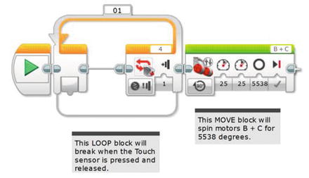
Figure 16-4. This MOVE STEERING block controls the GrabberBot’s movement down the tunnel
What if my calculations were a little off? Well, I did round the number of rotations from 15.384 (when I divided 60 inches by 3.9 inches earlier), so could this make my GrabberBot possibly bump the scroll? If you look again at Figure 16-3, you’ll notice that I have another foot-and-a-half of distance before the scroll, so I should be safe. That’s why I intentionally chose to stop the bot at the six-foot mark and not the seven-foot position.
Now I’m going to download my program and test it. I have a measuring tape, and I want to make sure that my bot moves forward about five feet and no more. I test it and . . . it works. I press the Start button (Touch Sensor), and the bot moves forward almost exactly five feet from its starting point. Excellent.
Because I need to take a deep breath at this point (and maybe you do, too), I’m going to have my bot pause for 10 seconds. I’m doing this because as I mentioned in Chapter 14, if I find that my bot isn’t lined up exactly where I want it, I could use a string tied to the rear of my bot and pull it back. It’s not the best solution, but I really want my bot to make one attempt on the scroll, and I want it to be successful. So I’ll add a WAIT block, which will let me look down the tunnel and make certain the bot is pointed directly forward and that the Grabber Jaw mechanism will fit smoothly underneath the scroll’s supporting legs (see Figure 16-5).
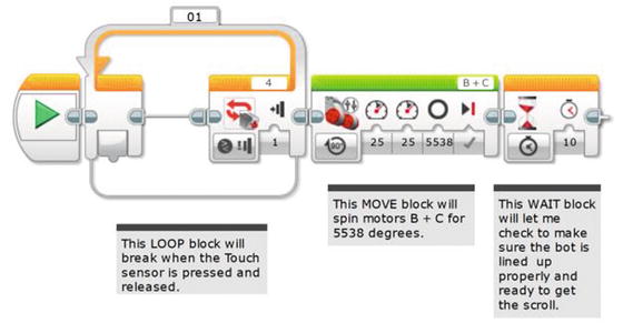
Figure 16-5. A WAIT block will let me check to make sure the GrabberBot is ready to get the scroll
I will tie a string to the rear of my bot, but hopefully I won’t have to use it. The WAIT block is just a safety precaution that I’ve decided to add—feel free to leave it out if you feel your bot is ready to move forward and grab the scroll.
Approaching the Scroll
Now, the next movement for my GrabberBot is a little trickier. The bot must crawl forward, very slowly, and try to detect the surface of the scroll. Why the scroll itself and not the back wall, you may ask? Well, my GrabberBot is designed so that its arm mechanism—the Grabber Jaw—will come in under the scroll and lift up. It’s small and low, and I’ve designed it to fit between the two support legs. If you take a look at my final GrabberBot design (refer back to Figures 15-1 and 15-57), you’ll notice that the Infrared Sensor is level with the center of the scroll. What I’ll do is test this over and over until I am certain the Infrared Sensor triggers at the right time—this position will be when the lifting arm is directly under the scroll, the best position for it to get a good lift-off. It could be one inch from the wall or less than that and I won’t know until I test it.
Since I need to test it, this is a good place for me to explain my test environment , shown in Figure 16-6.
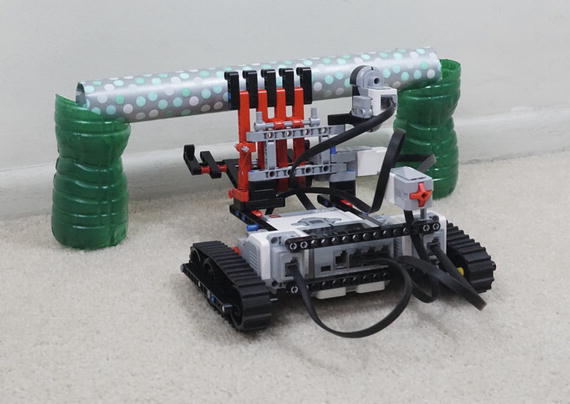
Figure 16-6. Photograph of the “scroll” and support legs
What I’ve done for my test environment is measure out 8 feet from a wall in my living room. I place some obstacles to represent the tunnel walls (okay, they are couch cushions—use what you have). I measure 4 inches from the wall and place two curved-cut plastic water bottles about 15 inches apart—these are the support legs for my scroll. These bottles are nice because they’re available everywhere and you can make them exactly the height you want. The inside edge—the lower part of the curve—is a precise 4 inches from the ground. The outside, taller edge is perhaps an inch higher, to create a nice appearance. (And in this case I spray painted them green, to make them easier to see in this photograph. That makes them more Mayan, too.) The whole arrangement requires your robot move with precision—if it is a little off it will tip the bottles over. You could use tin cans if you want the supports to be sturdy on their own.
And finally, for the scroll, I set on top of the support legs a piece of gift wrap with rolled-up newspaper inside. Simple, but it all works great.
Now, before I begin testing, I need to program my bot to slowly approach the scroll. To do this, I’m going to use a LOOP block that will break when the Infrared Sensor is triggered. So I first drop in that LOOP block (see Figure 16-7).
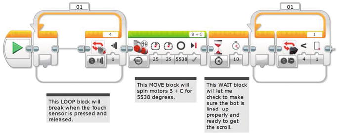
Figure 16-7. The LOOP block will break when the Infrared Sensor on port 1 is triggered
For now, I’ve configured the Infrared Sensor to trigger when it gets one centimeter from the actual scroll.
Next, I’ll drop in a Move Tank block (see Figure 16-8).
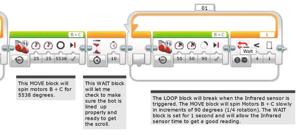
Figure 16-8. The Move Tank block will move the bot forward slowly for a short distance
I’m going to have the tank-tread motors B and C spin slowly (Power is set to 50), and a just a little bit at a time. The bot will move forward a short distance (90 degrees, which is .25 rotation), and the Infrared Sensor has a one-second delay to see whether the scroll is within one centimeter (see Figure 16-9). If it’s not, the bot will move forward again. It will keep doing this until the Infrared Sensor breaks the loop.

Figure 16-9. The one-second WAIT block in the loop allows the Infrared Sensor to get a good reading
Now I download the program and test. I tried four tests and found the Infrared Sensor stopped very close to the scroll every time. The Grabber Jaw was in the perfect position to do its work.
If I had mounted the Infrared Sensor high up to sense the back wall and not the scroll, I would have set it to look for the four-inch distance from the wall. That would be about ten centimeters. Then I would run a series of tests to make that distance exact.
Note
Every Infrared Sensor is different, and your Infrared Sensor will have a slightly different sensitivity than my Infrared Sensor. Because of this, you need to test your bot and record your own results. The final value for my Infrared Sensor (one centimeter) might not work with your GrabberBot. Although the Infrared Sensor is fairly accurate, always test with your own values, not the ones I am using—just to be safe!
At this point, my bot will now move down the tunnel and stop about two feet in front of the scroll. It then begins to move slowly toward the scroll (stopping and pausing every .975 inches—that is, 3.9 divided by 4 since it is set to 90 degrees) until the Infrared Sensor detects the wall and triggers the bot to stop. That little bot’s Grabber Jaw is directly under the scroll, ready to lift it up and return it to me.
Acquiring the Scroll
When my GrabberBot lifts the scroll off its support legs, I intend for it to pin the scroll against the Grabber Back Wall, held by the Grabber Jaw (flip back to Figure 15-58). By holding the scroll against those beams of the Grabber Back Wall, it is less likely that the scroll will roll or fall out of the arm mechanism on its return trip.
Now for this to work, I need Medium Motor A to apply continuous upward pressure against the scroll. To do this, I could simply put a MEDIUM MOTOR block into a LOOP set to loop Forever. But if I have the LOOP block configured this way, it will never break. How will the bot be given instructions to return with the scroll?
Engineering: Parallel Processes
The solution to this involves parallel processes. What are parallel processes? They are simply programming commands (that is, blocks) your bot will execute simultaneously. For example, you could program a bot with a Move Steering block that has motors B and C moving the bot randomly around the room, never stopping. At the same time, you could program the bot to also have motor A rotating the Sound Sensor back and forth, listening for sound input. So far, all of the bots in this book have only one block running at a time (like a WAIT block or a LOOP block). When one block finishes, the next block starts.
In order to program my bot to do two things at once, I will create another path where I’ll place programming blocks that will run simultaneously. But before I do this, I’ll finish this branch of the program as if motor A already has the scroll pinned. And when I have that done, I will go back and add that second sequence path containing the blocks for motor A.
Okay, so if I assume that my GrabberBot already has the scroll pinned, all that’s left is for the bot to move backward and return to the end of the tunnel. I’ll do this by adding in a MOVE TANK block for motors B and C (see Figure 16-10). I don’t want the bot to return too quickly, so I’m also going to program it for a slower speed (Power is set to 40).

Figure 16-10. A Move Tank block is used to bring the bot back to the tunnel entrance
That program with the reverse MOVE TANK should work, so now I’m going to add the necessary blocks for the bot to grab the scroll. To do this, I’ll be adding a parallel process as mentioned earlier.
The EV3 programming language allows us to do this by simply creating another execution path that breaks away from the main path. To do this, you need to first position the destination Medium Motor block that you want to hook up. As shown in Figure 16-11, that new Medium Motor block will be partially visible (or “dimmed”) to show it is not yet properly connected to any programming path.
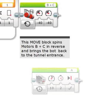
Figure 16-11. Place the destination Medium Motor A block. It will be dimmed as shown.
Then click on the point-of-origin as shown in the center of the enlarged Figure 16-12. The point-of-origin will turn blue when highlighted. You can now drag down from there and see a new path starting.
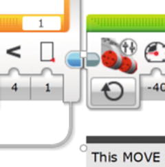
Figure 16-12. Click on the blue point-of-origin for your new parallel path
Now, while holding the mouse click, drag to the destination point. In our case, the left-side edge of the Medium Motor A block. When the path is established, it will turn gray and the destination block will change from dimmed to normal. You now have two parallel execution paths, as shown in Figure 16-13. That is, motors B and C will run at the same time as Medium Motor A. The EV3 software helpfully moved the MOTOR STEERING block a little to the side when the new path was added. We’ll move its comment block by hand, as shown in Figure 16-14.

Figure 16-13. Parallel execution paths, whereby the motors will run at the same time. We’ll reposition the comment by hand.
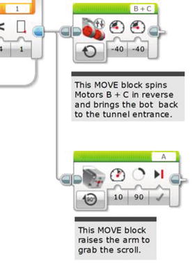
Figure 16-14. The Medium Motor block will spin motor A to grab the scroll. Give it a Power of 10 and 90 degrees of movement. The top comment is moved to the right and another comment added for motor A.
I can still place programming blocks on the original path, as you’ll see in Figure 16-15.
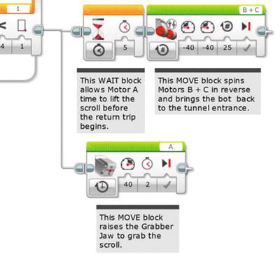
Figure 16-15. The WAIT block will give medium motor A time to lift the scroll
Engineering: Testing and Making Changes
At this point in the program, my Grabber Jaw is under the scroll, and I want it to lift up just enough to pin the scroll against the Grabber Back Wall of my GrabberBot. I’ll need to test motor A many times to determine the proper number of rotations or degrees to do this. But for now, I’ll place a MEDIUM MOTOR block to perform the lifting, as shown in Figure 16-14. I configure it to lift slowly (the Power is set to 10) and for 90 degrees.
Now I download and test the program. And I encounter four problems. The first problem is that the 90 degrees I’ve configured motor A to spin is not enough (the scroll’s weight may be the issue). I test it again and decide that instead of degrees, I’ll use time. Two seconds is a good setting to pin the scroll against the Grabber Back Wall. With it pinned, the Grabber Latch from Chapter 15 will hold it for the return trip. Or, you could not build the rubber-band latch, and simply keep the motor on for enough time to make it all the way back. That uses significantly more battery since the motor would be in a “stall” mode that takes lots of electricity to maintain. The rubber-band latch is an appealing solution if you’re going to run a large number of tests.
The second problem requires me to increase the Power setting from 10 to 40. I need this additional power to lift the weight of the scroll. Remember, test often!
The third problem is that setting the return B and C motors to ON should have worked. But it doesn’t. We’ve seen this before. You either need to put that MOTOR STEERING block in a LOOP or set it to enough rotations to get it all the way back. If the total distance is eight feet, that’s 96 inches. Each rotation gives us 3.9 inches of movement, so dividing 96 by 3.9 is about 25 rotations. That should fix it. The change is seen in Figure 16-15.
Engineering: Timing the Parallel Paths
The fourth problem requires a short explanation. When the program runs and the extra path splits off (see Figure 16-15), the program will execute the first block in the upper beam and the first block in the original beam at the same time. What this means is that motor A will lift (as we see the lower program execution path) at the same time as my MOVE STEERING block (in the upper, original path) instructs motors B and C to spin in reverse to return the bot. Big problem! The bot needs to first grab the scroll and then move in reverse.
To fix this, I’ll simply add a WAIT block that will run at the same time as motor A is lifting. I do this because I want to give the bot time to grab the scroll and pin it to the Grabber Back Wall before moving back down the tunnel. I’ll put in a WAIT block configured for five seconds, as shown in Figure 16-15. This five-second WAIT block allows the arm to close before the “reverse” MOVE block is executed and the robot returns with the scroll.
Let’s handle one last detail. Earlier we said there’d be a string attached to the back of the robot to pull it back if it did not travel in a straight line. But we should allocate some time to decide whether to pull it back. Add another WAIT block configured for ten seconds, as shown in Figure 16-16. That ten-second WAIT block lets the robot pause before the grabbing operation and gives us time to decide if this trip down the tunnel was a “keeper.”

Figure 16-16. An additional WAIT block gives the operator (Evan) time to decide whether to pull it back with the string
And once again, I test my bot. Because I’ve been testing my bot often, usually after each major programming block is added, my bot doesn’t require any additional changes. On its very first test, this is what happens:
I push the Start button (Touch Sensor).
The bot moves forward toward the scroll about five feet and stops. It doesn’t touch the tunnel sides at all (okay, cushions from my couch).
The bot moves .975 inches forward, the Infrared Sensor tries to detect the scroll and fails, and the bot moves forward another .975 inches.
The bot repeats Step 3 about six times before the Infrared Sensor is triggered.
Motor A spins, and the Grabber Jaw raises the scroll, pinning it against the Grabber Back Wall of the GrabberBot.
A few seconds later, the bot begins moving backward and brings the scroll back to me.
Perfect test!
Just to be sure, I perform two more tests with the GrabberBot, and they’re successful. With three successful runs of the GrabberBot, I am fairly confident in my bot’s ability to run down the tunnel, find the scroll, lift it off the support legs, and then return the scroll to me.
Take your GrabberBot and test it until you are able to successfully retrieve the test scroll a few times. When you’re ready, set up the scroll one final time and run the bot. If it works, congratulations!
You have the scroll, and the team is one step closer to finding King Ixtua’s burial chamber . . .