
There are many elements to this challenge’s bot. First, we have to figure out how to properly place the bot in the room. Then, the bot needs to take a picture of the library. After that, the bot needs to circle around the basket (still holding the twine) and return to the team so that they can pull the two ends of the twine to retrieve the basket and the key. Like I said, we have a lot to accomplish with this little bot. So let’s get to work.
SnapShotBot Planning and Design
In Chapter 6, I didn’t show you an initial picture of my final design for the StringBot. This was intentional, because I wanted you to start developing your own ideas for how the bot should look and function. I’m going to do the same in this chapter—I don’t want to show you the final design of my SnapShotBot because I don’t want to influence your planning and design ideas. That’s the great thing about building bots with the LEGO MINDSTORMS EV3 kit: no two bots are likely to ever look the same because you’re going to have your own ideas about how you want to solve challenges. So, no skipping ahead to Chapter 11 just yet. This is a challenging little bot to build and I want you to begin to focus on your own version of the SnapShotBot.
Once again, get a blank Design Journal page and pen and let’s move forward.
Note
There are three blank Design Journal pages left in the back of this book (if you used only one for Chapter 1 and one for Chapter 2). If you need more pages, feel free to make photocopies of the Design Journal page or visit the Apress web site to download the page in PDF format.
In the Robot Name box, go ahead and write SnapShotBot or, again, feel free to create your own name for the bot. Possible alternative names are LibRover, CamBot, or maybe StringBot2. After you’ve selected a name for your bot, it’s time to move on to its description.
The Robot Description
The secret to success with a robot that has this many jobs to do is to try to keep the Robot Description as simple as possible. Visualize the tasks the robot needs to perform and write down your Robot Description once you can see it in your mind.
Ask yourself this question: “If I were walking behind this bot taking notes of its actions, what would I see?” Write the answers inside the Robot Description box. Just as with the earlier bots, simply picture a small box on the ground and visualize this box doing what you believe needs to be done to complete the challenge (the box is a placeholder for your SnapShotBot, because you don’t know what it really looks like yet). Feel free to compare your Robot Description to the one I came up with, which is shown in Figure 10-1.

Figure 10-1. The SnapShotBot Robot Description is the best place to start planning its design
I’m guessing that your Robot Description doesn’t match mine word for word. And that’s okay. The main objectives you should have covered in your Robot Description include holding the twine, taking the picture, discovering the obsidian ring around the basket, navigating around the basket, and somehow returning to the team. Did you get all of it? If not, that’s perfectly okay. Why? Because sooner or later during your actual building of your SnapShotBot you would have realized that your bot was missing a task to perform and you would simply go back and write in the missing task into the Robot Description box. Simple!
Here’s another test you can do to make certain you’ve caught everything: pretend you are the bot! Look at Figure 10-2 for the layout of the library. Place a basket (or some other item) in the center of a room. Now walk through the tasks you need your bot to perform and compare them to your Robot Description. If you’ve missed something, just add it:
Move to the center of the room (holding two pieces of string) and turn left. (Easy . . .)
Take the picture of the library. (Piece of cake . . .)
Move toward the basket and stop. (Simple . . .)
Walk around the basket. (Check.)
Move back to your starting position. (Done.)
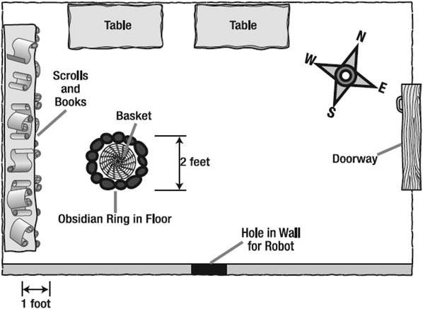
Figure 10-2. The King’s library
You’ll find that pretending to actually be the robot can reduce your design time because you’ll have a better understanding of the jobs your little bot must soon perform.
Okay, now it’s time for the Task List.
The Task List
Remember the purpose of the Task List? From your Robot Description, the Task List will help you break down the bot’s individual functions so that you can properly build a solution for each of its tasks—move forward, take a picture, stop when sensor is triggered, etc. Review your Robot Description and begin writing down each separate task the SnapShotBot will perform. My Task List for the SnapShotBot is shown in Figure 10-3.
Figure 10-3. The SnapShotBot Task List is built from the Robot Description
The Task List is probably the most important part for this Design Journal page; there are so many things going on with the SnapShotBot, and a well-documented Task List will help you keep track of all the actions for this challenge. Because this is such an important Task List, I’m going to cover each item in the list in a little more detail.
Task 1
The first task is “Move forward to the center of room and stop.” That seems pretty simple, doesn’t it? If you look back to Figure 10-2, you’ll notice that the room is square-shaped and that the distance from the bot’s starting position to the rear wall is 12 feet. Well, the halfway point will be 6 feet, but how do we tell the SnapShotBot to stop at 6 feet?
When you program the motors, you can only specify the number of rotations, the number of degrees of rotation, or the time in seconds to spin. With the ExploroBot, we looked at how we could figure out how many degrees we need to complete a turn. This six-foot-stopping problem benefits from the same kind of thinking. There are various ways you can get you your bot to stop at six feet. I’m including three of them here, but there are many more methods:
Time in seconds: Using a stopwatch, record how many seconds it takes your bot to move six feet. That’s how many seconds you should run the motors to place the bot close to the halfway point.
Number of rotations: Determine the circumference of the bot’s wheels (the distance around the tire) in inches. Divide 72 inches (6 feet = 72 inches) by the wheel circumference and that will tell you how many rotations to program the bot’s motors to spin to place the bot halfway across the room.
Number of degrees of rotation: Gently push the robot across the floor six feet and, using the Brick’s View option of the feedback panels in the configuration pane, record how many degrees of motor rotation the move takes. (This is just like what we did with the ExploroBot to measure our turns!)
For my SnapShotBot, I’m going to use the second method. I’ve measured a wheel and determined that the wheel’s circumference is 5.5 inches. When I divide 72 inches by 5.5 inches, the number I get is 13.0. Will this be exact enough, since I only measured the wheel’s circumference with a cloth tape measure? Don’t worry; just getting it close to the middle of the room will be enough, so you don’t have to be exact. So, when I program my bot to move to the center of the room, I’m going to set the motors for a duration of 13 rotations.
Task 2
Okay, now that the bot is in the center of the room, let’s take a look at Task 2, “Turn Left to face library.” You already know how to do this task from Chapter 4. You can refer to Chapter 4, after you build your bot, to find the instructions for manually turning your bot 90 degrees and getting the correct angle to turn one of the motors, but here’s a quick summary:
Turn on the Intelligent Brick.
Use the Brick’s right or left button to scroll to the View option and then press the dark gray Select button.
Use the right or left button to find Motor Degrees and then press the dark gray Select button.
Select a port to monitor (I’m choosing Port B for the wheel on the right side of the Brick) and press the dark gray Select button.
Place the SnapShotBot on a flat surface and press the dark gray Select button to reset the counter.
Twist and turn the SnapShotBot left 90 degrees so that only the right-side wheel turns.
Write down the result displayed on the LCD screen. (For the record, I got -678 degrees.)
Press the dark gray Select button to reset the counter.
Twist and turn the SnapShotBot right 90 degrees so that only the left-side wheel turns.
Write down the result from the LCD screen. (For this turn, I got -640 degrees.)
The first turn your bot will make is a left turn. But later your bot will also make a right turn, so be sure to record both results (left and right turn). Record these values somewhere on your Design Journal page. (Of course, you’ll perform these steps after you’ve built the robot.)
Task 3
Task 3 is for your bot to take a picture, so let’s give this a little thought. We’ve already allocated two large motors to control the right and left wheels. So, we’ll use the third, medium motor to build a device that can press the button on a smartphone or a disposable camera. Can you picture the robot in the middle of the room, facing the library? The robot is low to the ground, so I’ll probably want to angle the camera up a little bit so it can take a better picture—I’ll have to remember to put that in my Mindstorm section. I’ll also need to make some sort of holder for the camera. At this point, Task 3 is simple enough—I just need to plan on something to hold the camera and something that will allow the motor to press the button.
Task 4
Task 4 is “Move forward until black obsidian ring is detected and stop.” From the Robot Description of the obsidian stone ring, we know that it’s a different color than the stone used in the rest of the floor. This is a perfect test of our Color Sensor. The Color Sensor can detect changes in color, so we can add the Color Sensor to our bot and program it to detect the color of the regular floor. We can also program the Color Sensor to detect a change in the sensor reading as the bot begins to move forward toward the ring. When the sensor reading drops (black will give a lower reading than the brown stone color), we’ll instruct the bot to halt.
This is a good place to stop and do a few experiments with the Color Sensor. After you build your SnapShotBot, you’re going to set up a test environment. So, right now you need to figure out where you’re going to perform your test. Possible locations are a living room floor (wood floor or carpet), a garage floor, or even a tile floor; as long as the floor isn’t black or a very dark color, you shouldn’t have any trouble. Once you determine your test floor, find a piece of black paper (or a piece of paper that is much darker than your floor color). Now, here’s what I want you to do:
Turn on the Intelligent Brick. The screen might look like Figure 10-4 if there is no program loaded.
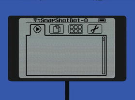
Figure 10-4. The starting screen
Use the Brick’s right or left button to scroll to the View option (third tab). This will place you on the Port View selection, as shown in Figure 10.5.
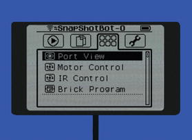
Figure 10-5. The View screen with the Port View selection highlighted
Then press the dark gray Select button. If your Color Sensor is attached to Port 1, the screen will look like Figure 10-6.
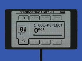
Figure 10-6. The Color Sensor screen in the COL-REFLECT mode
If needed, use the right or left button to select the port used by your Color Sensor and then press the dark gray Select button—the LED light on the Color Sensor should turn on and shine red light, if it is not already doing so. Your screen would look like Figure 10-7.
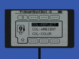
Figure 10-7. Selecting the COL-REFLECT mode
It should be on the COL-REFLECT option. If necessary, use the up or down button to select COL-REFLECT. Then press the dark gray Select button and your screen should resemble the one in Figure 10-6.
Point the Color Sensor near your test floor’s surface. A good result can be achieved by holding it no more than two to three centimeters above the surface.
Write down the result displayed on the LCD screen for the “normal surface.”
Place the black (or dark) paper under the Color Sensor at the same distance and notice the value changes.
Write down the new result displayed on the LCD screen for the “obsidian surface.”
Record the results of your test somewhere on your Design Journal page. Write Normal Floor and the number that was displayed for it, and then write Dark Paper and the number for it, too. You’ll need these numbers when you begin to program your bot.
Okay, so now your bot is near the basket. The next four tasks are simply steps to get the bot around the basket and heading back in the direction from which it came.
Task 5
Task 5 starts the journey around the basket by having the bot turn right, move forward a little bit, and then stop. But what do we mean by “a little bit”?
Well, we know that the black obsidian ring surrounding the basket is about two feet wide and two feet long (we see this in Figure 10-2). And earlier in the chapter, you found out that the circumference of the wheels is about 5.5 inches. We also know that the bot should be near the center of the ring, so let’s figure out how many rotations we need it to make to get safely around the basket.
As shown in Figure 10-4, after the bot turns right, it needs to move only about one foot forward (to Point A). One foot is 12 inches, so we divide that by the circumference of our wheels (that is, 12/5.5 inches = 2.2 inches). That tells us we should program the bot’s motors to spin 2.2 rotations, which should place it close to Point A. On the back of your Design Journal page, copy Figure 10-8 and write down the rotation values you calculate—between the bot and Point A, write Rotations: and the number that you calculated.
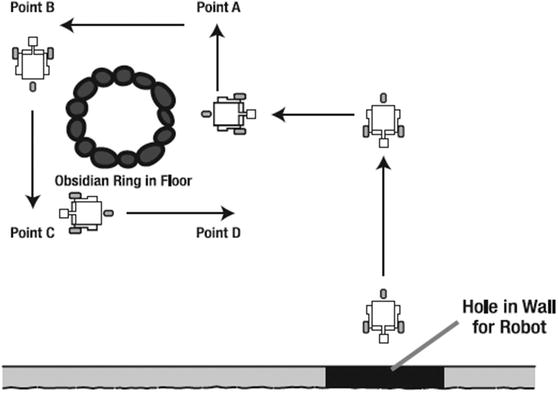
Figure 10-8. The SnapShotBot needs to go around the basket
Task 6
Task 6 says “Turn left, move forward short distance and stop.” Again, what is a “short distance?” Well, Figure 10-2 tells us the ring is two feet in diameter. So, in Figure 10-8 we can see that the distance from Point A to Point B would be about 4 feet, or 48 inches. Once again, divide 48 inches by the wheel’s 5.5-inch circumference and we get about 8.8 rotations. On your map, write down Rotations: and the number calculated for the motors to spin between Point A and Point B.
Task 7
Task 7 is identical to Task 6. This will get you from Point B to Point C. Write Rotations: on your map and then write the number calculated for the motors to spin between point B and point C (that is, 8.8). Just to be safe, if you like you can add in another few rotations to make certain the bot gets completely around the basket. Now you have the proper number of rotations to get your bot to point A, then from point A to point B, and finally from point B to point C (or slightly beyond point C).
Task 8
Starting at point C, your bot simply needs to make a left turn and move back to the center of the room. If everything has been done properly, your SnapShotBot will have encircled the basket with the two pieces of twine that will be used to pull the basket.
Task 9
Okay, so let’s pretend that the SnapShotBot is moving back to the center of the room. You, as an archeology team member, will be looking through the small opening in the wall. As soon as you see the SnapShotBot, you need a way to tell it to stop, turn right, and come back to you. Won’t the Remote Infrared Beacon work perfectly here? Task 9 is “Stop when Infrared Sensor is triggered,” and this task will be easy to handle. You’ll need to remember to include the Infrared Sensor and its remote in the Mindstorm section later in the chapter.
Task 10
Task 10 is our final task: “Turn right and move forward to library exit.” Once the bot has stopped (triggered by the remote’s signal to the Infrared Sensor), it will turn 90 degrees to the right. You recorded the number of degrees needed to make a right turn earlier, remember? After the bot has turned, it should be facing the opening in the wall. Start the bot moving forward and just wait for it to come back to you—that’s it!
What About the Twine?
Now, you may have noticed there’s no mention of the twine in the Task List. I intentionally left it out because it’s not really a bot task (well, other than to pull the string). You’ll need to include some sort of beam or component where you can tie two pieces of twine to the SnapShotBot. When the bot returns to you after completing Task 10, you’ll use the two ends of twine that you held on to (while the bot was moving in the library) and the other two ends of twine tied to the bot and you’ll PULL! As you pull on the twine, the twine will catch on the basket and allow you to pull the basket toward you!
This was a long Task List, but this bot has a lot of things to do. We’re not done just yet, though. Hopefully, as you were thinking about the tasks involved, you came up with some limitations or constraints that you will need to keep in mind as you begin building.
Limitations and Constraints
Your bot has one primary job—to go around the basket while holding the twine and return to the team. There are no obstacles in the way (other than the basket itself), and all you have to worry about are the walls and tables. If you can just navigate your bot around the basket, you’re home free. The few limitations I came up with are listed in Figure 10-9.

Figure 10-9. The SnapShotBot does have a few limitations to think about
As for taking a photograph, however, there is a small limitation to consider. Your bot will most likely be fairly low to the ground. (A tall bot is more likely to tip over or possibly be wobbly, but I don’t want to put any limits on what your SnapShotBot will look like. If you choose to build a taller bot, you may find that you have an additional constraint or two to work around, but that’s all part of the fun, right?)
For my little bot, if I simply set the camera on top of a flat spot, the final picture will be of mostly the lower part of the library wall. I want to get as large a picture as possible, showing as much of the books and scrolls as I can manage. Because of this limitation, I’m fairly certain I’ll have to angle the camera back a little bit so that it’s pointing slightly upward. Just imagine you are the bot, down low on the floor. Look up to the middle of the wall, and that’s the angle that you’ll want to use to mount the camera.
One minor constraint that I also added involves the twine that will be tied to the bot. Imagine a dog on a leash. If you hold the leash tight, the dog will not be able to continue moving away from you. The same goes with your robot. You’ll need to keep feeding out a lot of additional twine so the bot never gets stopped. There’s also a risk of the bot moving a little off course if the twine ever gets tight. So, my best recommendation to you is to provide a lot of slack to your bot by paying attention to the tightness of the twine and never letting it get too tight.
Did you come up with any additional constraints? If so, write them down in your Limitations/Constraints section and keep them in mind during the building and programming of your bot.
Mindstorm
Most likely, you’ve already got an image in your mind of what your SnapShotBot will look like. Feel free to look at Chapter 11 if you’d like to see my final version of the SnapShotBot. My guess is that my version doesn’t look like what you’re imagining. Am I right? Perfect!
For this bot, you’re welcome to use my steps to build the SnapShotBot, but maybe you’re feeling good about your design skills at this point and want to build your own version first. Give it a try! If you get stuck, take some of my ideas. The goal is for you to try to build your own version of this bot. And the Mindstorm section of your Design Journal page is the ideal place to begin putting down your ideas before you begin to build.
In Figure 10-10, you can view my ideas for my bot in the Mindstormsection of my Design Journal page.
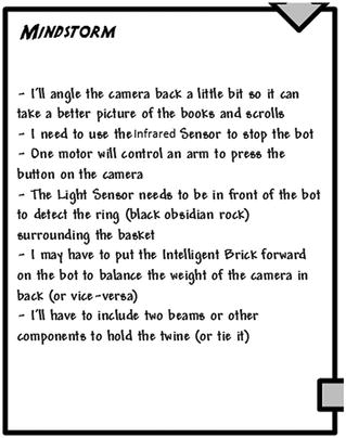
Figure 10-10. The Mindstorm section for my SnapShotBot
The first Mindstorm item was mentioned in the previous section: “I’ll angle the camera back a little bit so it can take a better picture of the books and scrolls.” Because the books and scrolls are stacked along the left wall (see Figure 10-2) and the bot is so low to the ground, I’ll angle the camera back and it will be able to take a picture that doesn’t include most of the floor. As stated earlier, if the camera is just facing directly forward, the final picture will contain a large portion of the floor and lower wall. This might be okay for you, so feel free to place your camera any way you like.
Again, I’m not going to cover every item on my Mindstorm list, but I would like to cover two more that I feel are important. First, “The Color Sensor needs to be in front of the bot to detect the ring (black obsidian rock) surrounding the basket.” This is easy to understand. If you place the Color Sensor on the back of your bot, there is a chance that your bot might hit the basket before stopping at the black ring. Placing the Color Sensor at the front of the bot allows the bot to detect the black ring early and stop before most of the robot body crosses inside the ring (and possibly collides with the basket).
Second, “I may have to put the Intelligent Brick forward on the bot to balance the weight of the camera in back (or vice versa).” This is based on my experiences with building small bots with the MINDSTORMS EV3 kit. Too often, I’ve found that some of my bots tend to have too much weight in the front or back or on a side. Because of this, some bots are unbalanced, increasing the risk of tipping over. As I build my bot, I’ll try to remember to place the Brick and the camera (with its motor) on opposite sides of my bot. I might choose to put the camera in front and the Brick in back, or vice versa. I haven’t decided yet on this point and will probably wait until I begin to build.
Now, take your Mindstorm ideas, your Task List, and the Robot Description and pull them all together by creating some sketches—these will help you when you start to build. When you have an idea in your mind, putting it down on paper will help you start snapping pieces together in a logical manner to achieve that mental image. So let’s finish up with the Sketches section of your Design Journal page.
Sketches
Alright, I’m warning you again to keep the snickering to a minimum! My sketches aren’t the best, but I think you’ll get the idea. Take a look at Figure 10-11 to see my rough sketches of the (soon-to-be-built) SnapShotBot.
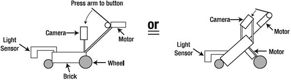
Figure 10-11. I’m using basic shapes to represent parts of my SnapShotBot
Notice that I’m not drawing with extreme detail. Yes, this is partially because I’m not the best artist. But more importantly, it’s because I don’t need to draw every beam and connector and sensor to develop a working shape and concept of where everything will go. Wheels are circles, the Brick is a rectangle, sensors are smaller rectangles, and motors . . . well, the motors just look weird. Sorry.
After you complete your sketches, there’s no point in waiting, so start building! Take everything you’ve written and drawn on your Design Journal page and build your version of the SnapShotBot . . . or whatever name you have given it.
In Chapter 11, you’ll find the step-by-step instructions for building my version of the SnapShotBot. Steal ideas from it—or just ignore it all—and make your version bigger (or smaller), better, faster (or slower), and as unique as you can imagine.