
Your ExploroBot looks nice, but it really doesn’t do much yet, does it? That’s about to change. In this chapter you’re going to create the program that sends the bot down the tunnel (and back) to trigger the locked tomb door. So, let’s get started.
Some Experience Required
This chapter isn’t about teaching you the basics of the software. Included with the LEGO MINDSTORMS EV3 software is a collection of software tutorials. At this point, I’m assuming that you’ve built the bots included with the MINDSTORMS EV3 kit and you’ve gone through the tutorials for programming the bots. During these tutorials, you received some basic skills in selecting programming blocks, dropping them into the workspace, and configuring the blocks.
In this chapter, I’m going to show you how to use your completed Design Journal sheet for the ExploroBot to help you construct the program, block by block. So go ahead and open the LEGO MINDSTORMS EV3 software (see Figure 4-1).
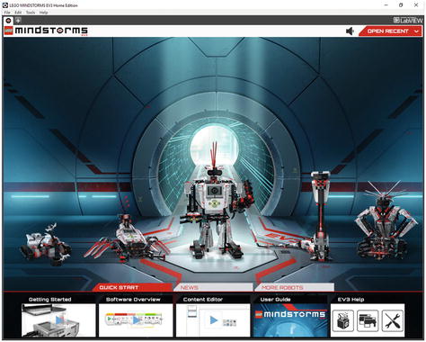
Figure 4-1. The LEGO MINDSTORMS EV3 software
You’re going to create a new project and program, so touch the Plus sign tab at the upper-left corner. Click on the default title Project and type ExploroBot, replacing the default title (see Figure 4-2).
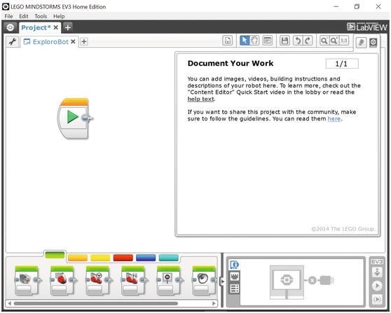
Figure 4-2. Enter a name for the new program underneath the Project tab
Note
To have more workspace visible on your screen, minimize the Document Your Work area on the right by clicking the EV3 Button symbol at the far right of the top tab bar. (This symbol is shaped like a little stop sign—that is, an octagon. It resembles the buttons on your EV3 Intelligent Brick.)
Now, before we start dropping blocks all over the place, we need to think about what this program is supposed to do. Remember the Task List from the Design Journal? This is where that list is going to come in handy (see Figure 4-3).
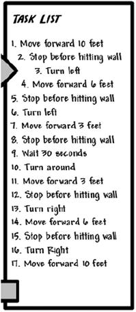
Figure 4-3. The Task List will help us program the ExploroBot
We’re going to use each of the numbered items from the Task List to determine what types of programming blocks will be placed on the workspace. Like the construction of the actual ExploroBot, there are also numerous ways to program the bot. As you experiment with the LEGO MINDSTORMS EV3 software (often called EV3-G for short), you’ll probably discover new (and better) methods for programming. You might find a way to shorten the program so it takes less memory space in the Intelligent Brick. Or you might choose to switch out the Infrared Sensor with the Touch Sensor, which requires slightly different programming blocks. My point is this: there’s no perfect method for programming the ExploroBot. With that in mind, let’s do a little planning before dropping some blocks.
Take a look at the Task List’s first item: “Move forward 10 feet.” What do you think—maybe throw in a Light Sensor block? Just kidding. The bot first has to move forward down the tunnel, so that means a Move Steering block (see Figure 4-4).
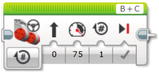
Figure 4-4. The basic Move Steering block. This one can control two motors at once
Note
You drag and drop a Move Steering block from the green tab, as highlighted in Figure 4-2. The colored tabs each represent a different category of blocks, such as Action, Flow Control, Sensor, etc. You can hover over each tab to see which category it is. It is worth investigating all the tabs, which will help to familiarize you with the other available programming blocks. If you find one you’re not familiar with, drop it on the workspace and play around with it for a few minutes. There’s no rush.
We’ll configure the Move Steering block a little later. For now, let’s move to the next Task List item: “Stop before hitting wall.” Obviously, this would use a Touch Sensor or Infrared Sensor. The ExploroBot in Chapter 3 uses the Infrared Sensor, so we know we’ll be configuring it later.
One interesting thing to note is that the bot will make four left turns during its travel down the tunnel. How did I come up with this number? Take a look at Figure 4-5 and you’ll see all four turns.
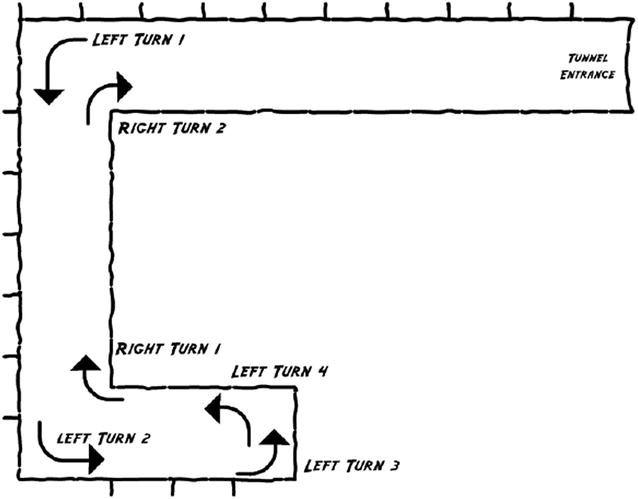
Figure 4-5. The ExploroBot will make four left turns and two right turns during its travels
After the robot has reached the end of the tunnel and turned completely around, it will make two right turns on its way out of the tunnel (see Figure 4-5).
Now, why is this important? Because when programming, sometimes it pays to try to reduce the amount of work you need to do. And the EV3-G software comes with a useful block that will save you some time. We’re going to use the LOOP block here (see Figure 4-6).
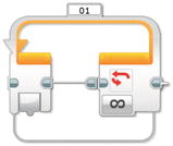
Figure 4-6. The basic LOOP block
The final block I want to discuss is the WAIT block (see Figure 4-7). When the ExploroBot reaches the trigger, I want it to stay there for a short period of time, just to make sure the pressure plate is triggered.

Figure 4-7. The basic WAIT block
With these four blocks, you have all the tools you need to program the ExploroBot to perform its duties.
Into the Tunnel
To save some time, I want you to look at the Task List again. I’m going to group some of the tasks together like this:
(Group 1) Forward – Detect Wall – Stop – Turn Left (first corner)
(Group 2) Forward – Detect Wall – Stop – Turn Left (second corner)
(Group 3) Forward – Detect Wall – Stop – Turn Left (end of tunnel)
Turn Left (this final turn is so the bot is pointed in the direction to leave)
Notice the first three groups are identical. When programming the ExploroBot, you could choose to place a Move Steering block, another block for the Infrared Sensor to detect the wall, another block to stop the motors, and another block to turn the bot left. And this will only get you past the first corner! You’ve still got group 2 and group 3 to go!
This could take a while. But not really. You’re going to use the LOOP block in such a way that you can have the ExploroBot do all three groups with minimum programming. First, place a LOOP block after the START block (see Figure 4-8). It’s not much to look at, but hang on.
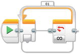
Figure 4-8. You’ll start with the LOOP block to save some time
The LOOP block repeatedly executes blocks within it (inside its orange borders) an unlimited amount of times or a specified number of times. The LOOP block can also repeatedly execute a sequence of blocks inside it until a condition is met (such as a sensor being triggered). You can even put a LOOP block inside a LOOP block!
Note
Putting a LOOP block inside another LOOP block is called “nesting.” We’re going to use this concept with the ExploroBot. Keep reading.
Because you have three groups of similar tasks, you’re going to set this first LOOP block to run three times. After you’ve dropped the LOOP block onto the workspace, take a look at how the LOOP block is configured (see Figure 4-9).
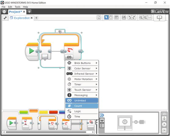
Figure 4-9. Configuring the LOOP block
From the Control drop-down menu, select Count. In Figure 4-9, Unlimited is highlighted in darker blue, since it is the control type presently selected (that is, the infinity sign, representing Unlimited). When you hover over Count, it is highlighted in lighter blue, confirming that it is the one you want to select. Press Count. Then, your block will look like the one in Figure 4-10.
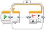
Figure 4-10. The LOOP block set to Count, but only 1 time
You now have a Count text box. Click on the numeral 1 and enter the numeral 3. That means that any blocks or actions that you place inside this loop will be performed three times before this LOOP block is finished and the program continues. Now, what goes in the loop? Would you believe another LOOP block?
You want the ExploroBot to begin rolling down the tunnel and continue until the Infrared Sensor detects the first corner, right? Well, to program this you need a Move Steering block to continue turning Motors B and C until the Infrared Sensor detects the wall. To do this, you’ll place a Move Steering block inside a LOOP block that’s configured to use the Infrared Sensor to break the loop. Your first step is to just drop another LOOP block inside the first LOOP block (see Figure 4-11); it will expand to allow the new LOOP block.
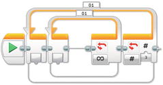
Figure 4-11. Nest another LOOP block inside the first LOOP block
Now you need to configure the inner LOOP block to use the Infrared Sensor (see Figure 4-12). Using the configuration panel for the inner LOOP block, click on its infinity sign to change the Control section to Sensor. In the Sensor section of the drop-down menu, select Infrared Sensor and set it to Proximity. You’ll see a 4 next to it, which is the default setting giving you < (Less Than). That we can leave unchanged. The Distance setting defaults to 50, which you’ll change to 5, representing five inches. Figure 4-12 shows the two LOOP blocks after you’ve made these changes.
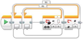
Figure 4-12. The nested Loops configured to run the inner LOOP block three times
Note
At the end of this chapter, I’ll cover testing of the ExploroBot. The setting of five inches might not be correct for your ExploroBot. You’ll have to test different sensitivities of the Infrared Sensor to determine the proper distance for the sensor to break the Loop and stop the bot’s forward movement.
Next you’ll drop in the Move Steering block (see Figure 4-13) and click on the symbols to configure it. You want the motors to turn continually and only stop when the Infrared Sensor breaks the LOOP block. You’re also using large motors B and C and motion set to forward. Click the circular symbol in the lower left of the MOVE block (indicated with black arrow). A pull-down will appear. The default is On for Rotations. Move your cursor to On and click.
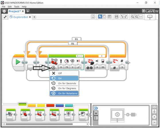
Figure 4-13. Place a Move Steering block inside the inner LOOP block
Once the LOOP block is broken (by the Infrared Sensor), the bot needs to stop the forward motion and turn left. This also is done three times (see the earlier three groups). Now you need to drop in a block to stop the motors, and another block to turn the bot.
First, let’s drop in a Move Steering block to stop the motors (see Figure 4-14). It’s easy to configure. Just select the Stop action (as shown) instead of forward movement. This is represented by an X in the lower-left side of the block.
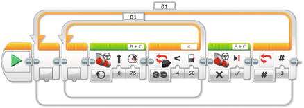
Figure 4-14. Another Move Steering block stops the motors from turning
The final action for the outer LOOP block is to turn the bot to the left. We’ll drop in a block called Large Motor and configure it to run at 25% power for 360 degrees of rotation (see Figure 4-15). We have not used this block before. It controls the large motor as the Move Steering block does, but only operates a single selected large motor instead of two motors.
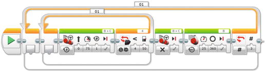
Figure 4-15. This Move Steering block turns the bot to the left
Engineering: Encoders: How Does a Motor “Know” Where It Is?
We’re going to tell the motors to turn a certain number of degrees. But how do they “know” where they are, or how far they have to go? These motors contain a circuit called a motor encoder. This allows the motor to “know” where it is in terms of rotations. So if you command a motor to turn, say, 180 degrees, it will turn from its present location until it fulfills that many degrees. It will not simply “give up.”
As an example, if you have a jaw that is supposed to close on an object, you might tell it “turn 90 degrees” and find that it does close that far. However, what happens if something is blocking its motion? At that moment, the encoder circuit has read that it turned, say, 75 degrees. But the command was to go for 90. The encoder is operating from a command to get to 90, so it tells the motor to keep turning. That is why it won’t “give up.” And that means your program stays on that block until the full move has happened! It will not proceed until it has done what it was told to do.
Returning to our ExploroBot, only one motor (B) is configured to turn in this Large Motor block. When motor B turns and motor C is motionless, the bot will turn left. At the end of this chapter, I’ll show you how to determine the proper number of degrees needed to make a good left turn. For now, let’s set it to 360. We’ll also cut the power down to 25 for this block to make the turn slow and steady.
Let’s pause here and take a look at what we’ve done. I’m also going to ask you to add some comments to your program. Comments are a built-in feature of the software and will come in handy if you ever want to make changes later or give the program to a friend. With comments, someone else looking at your program should be able to follow along and better understand what your program does and why.
At this point, you’ve got an outer LOOP block that will run three times. Everything inside it will occur three times and three times only. This means the bot will move forward until the Infrared Sensor detects an obstruction in its path (the tunnel wall), stops moving, and turns left—three times. If you go back to Figure 4-5, you’ll find that when the outer LOOP block completes, the bot should be sitting on the trigger and facing north.
I suggest that you use the Comment tool (see Figure 4-16) and type in a description of the blocks that you’ve just created. In Figure 4-16, I’ve included my comments for you to see.
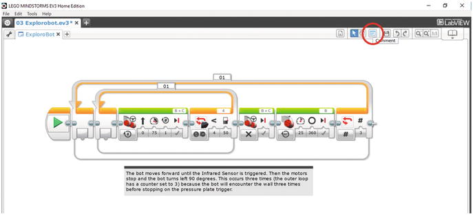
Figure 4-16. Place comments for your blocks using the Comment tool (circled in the upper right)
Now that the robot is on the trigger, let’s go back to the Task List. Step 9 is for the bot to pause for 30 seconds. This is simple—you just drop a WAIT block at the end of the program and set it for 30 seconds (see Figure 4-17).
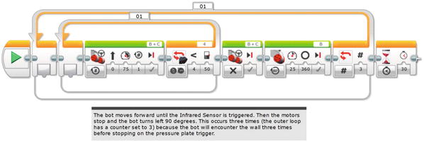
Figure 4-17. A WAIT block is added for the bot to pause on the trigger
Because the bot is facing north, you need it to make one more left turn (see Figure 4-5) so it can go back the way it came and leave the tunnel. Easy enough. Just drop a Large Motor block in and configure it like the other Large Motor block that turns the bot (see Figure 4-18). Like the earlier Large Motor block, let’s set this one with a power setting of 25 and duration of 360 degrees until we determine the actual turn required.
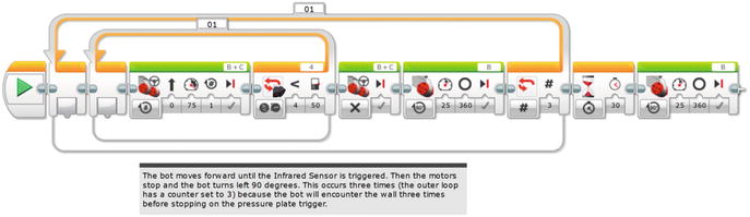
Figure 4-18. A Large Motor block is added to make the final left turn
Figure 4-19 shows a comment I’ve added at this point in the program. Again, I highly recommend comments. You never know when you might come back to this program and having comments will quickly help you to refresh your memory of how things work and are configured.
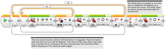
Figure 4-19. I’ve updated the comments in the program
At this point, it’s time to program the exit of the ExploroBot.
Out of the Tunnel
Right now, the ExploroBot is facing west, ready to begin its exit from the tunnel. Just like the entrance, the bot will make some moves that are duplicates:
(Group 1) Forward – Detect Wall – Stop – Turn Right (second corner)
(Group 2) Forward – Detect Wall – Stop – Turn Right (first corner)
Turn Right (this final turn allows the robot to leave the tunnel)
So, once again, there’s an opportunity to use two LOOP blocks, one nested inside the other. There are just a couple differences with these two LOOP blocks:
The bot will be making right turns instead of left turns.
The bot will make two right turns, so the outer LOOP block needs its Count set to 2 instead of 3.
Knowing this information, let’s place the two LOOP blocks and configure the outer LOOP for three repetitions and the inner LOOP for the Infrared Sensor (see Figure 4-20). But didn’t I say that it only needed to make two right turns? After that second right turn, you want the bot to keep rolling. It won’t encounter another wall, but it should encounter your hands, waiting for it to come out of the tunnel. For that reason, you can configure this LOOP with a count of 3, even though it won’t make an actual third turn.
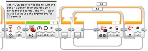
Figure 4-20. Two LOOP blocks placed and configured
Next, place three Move Steering blocks : one for moving the bot, one for stopping the motors, and one for turning the bot. The first Move Steering block is configured with Unlimited duration for Motors B and C. The second Move Steering block is configured to stop motors B and C, and the third Large Motor block is configured to turn only large motor C at a power level of 25 and a duration of 360 degrees (see Figure 4-21).
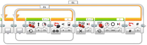
Figure 4-21. Place two Move Steering blocks here, followed by the third Large Motor block
Comments are placed describing these new LOOP and motor control blocks (see Figure 4-22).
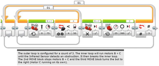
Figure 4-22. Comments are added to describe these new blocks
That’s it. Well, not quite. But we’re close. Remember all those Large Motor blocks that turn the bot? We set them to 360 degrees. That was just a guess. When I downloaded this program to my ExploroBot and ran it, those 360 degrees of rotation on the motors actually turn the bot only about 20 degrees to the left. To make those right and left turns, we’re going to need the motors to turn quite a bit more. Luckily, the Intelligent Brick comes with a nice little tool to help you determine the correct number of degrees needed to turn the bot. Read on . . .
What the Degree, Kenneth? (With Apologies to REM)
Engineering: Measuring Actual Motor Rotations from the Brick Screen
First, I need you to turn on the EV3 Intelligent Brick.
Using the Brick’s right or left buttons, scroll through the list of options until you find Port View. This will be the third tab from the left. Press the center dark gray Select button on the Brick, which will give you the third screen in Figure 4-23. Now you’re going need to select the port to monitor. The first turn will be done by motor B, so use the up button to get to the top row (showing motor status) and then the right button to get to port B. As you get there, you’ll see that the LCD screen will show B:L-MOTOR-DEG, with the number 0 deg below. (These EV3 Brick screens are shown in Figure 4-23.)
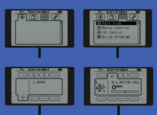
Figure 4-23. Choosing the motor Port B to see 0 degrees as its starting point
Just for grins, turn the wheel on motor B and watch what happens on the screen. That number tells you how many degrees the motor turns. If you turn the motor forward, you’ll get a positive number (1 and climbing). If you turn the motor backward, you’ll get a negative number (-1 and dropping). Press the center Select button to reset the degree counter.
Now, place the ExploroBot on a flat surface and press the center Select button again to reset the counter. Next, manually turn the ExploroBot 90 degrees to the left. For best results, try to keep the wheel for motor C from rotating. Just steadily turn the ExploroBot left so that the wheel on motor B turns. When you’re done, take a look at the LCD screen. Your results may be different, but for my ExploroBot I got a reading of 535 (see Figure 4-24). Now do the same thing for port C. A true right turn, done the same way, should give you the same result for motor C (or very close).
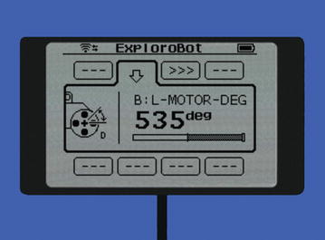
Figure 4-24. Observing how many degrees the motor on port B rotates, with the ExploroBot turned 90 degrees by hand
The degrees you get for large motor B and large motor C is the number you’ll enter for the Duration setting for the Large Motor blocks used to turn the ExploroBot. (See Figures 4-15, 4-18, and 4-21 for coverage of the three Large Motor blocks used for turning.) Go back and enter the number for all three Large Motor blocks (two for motor B and one for motor C). Save your changes and upload the updated program to your ExploroBot.
Keep in mind that your ExploroBot will be different from every other ExploroBot—some motors are little more stiff, some less so. My rubber wheels might behave a little differently on a wood floor versus a concrete floor. Battery levels will be different. There are so many factors that can affect how your ExploroBot operates. Don’t get frustrated . . . just tweak and tweak and then tweak some more (see my own tweaks at the end of this chapter).
At this point, you’ll have to do some testing to determine that the right and left turns are as close to 90-degree turns as possible. Don’t take risks—if the bot is off by a few degrees, you’ll take the chance that your bot might not go straight and get stuck somewhere where you can’t reach it. You want the bot to turn as close to 90 degrees as possible and then move forward on a straight path. Tweak the individual Duration settings until you’re happy that the bot is turning left and right correctly (see Figure 4-25).
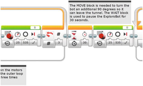
Figure 4-25. I’ve entered 535 for the Duration settings on my three MOVE blocks for turning
Opening the Tomb Door
Now it’s time to simulate (that is, test) the tunnel challenge. If your ExploroBot navigates a test tunnel and returns successfully, great job. You can rest assured that the real tunnel would be no challenge to your well-designed bot.
Here are my suggestions for setting up your test tunnel.
Note
You don’t have to construct a real test tunnel to get results. Remember, your bot simply needs to move in fairly straight lines, react properly to obstacles (by turning left or right), stop on the “trigger” and wait, and come back to the starting point.
For my test “tunnel,” I used the wooden floors of my home. I found a large open area and measured a distance of ten feet. At the end of the ten feet, I stood up a hardback book to simulate the wall of the first corner.
Next I measured six feet to the left and placed another hardback book to simulate the wall of the second corner.
For the end of the tunnel, I measured three feet left from the second corner and placed three hardback books to simulate the dead end (see Figure 4-26). If I run this as a challenge for several people, I’ll make walls along the whole route, using boxes. I’ll also tape a six-inch square of paper for the pressure plate in the center of the three books.
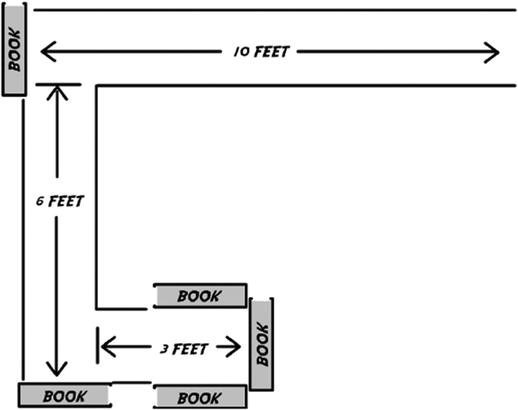
Figure 4-26. Bird’s-eye view of my test “tunnel”
And my results? It took four runs before I was successful in having my ExploroBot return to me. Here’s a summary of the runs:
First run: My ExploroBot got too close to the wall before stopping. The simple fix for this was to change the Infrared Sensor setting from five inches to seven inches. The Infrared Sensor detected the wall earlier and was able to stop the bot so it had room to turn properly.
Second run: When the ExploroBot successfully stopped at the wall and turned left, it turned just a little less than I needed. My original motor B setting was 535 and I changed it to 550.
Third run: I had the same problem as the second run, but this time it turned a little too much. I had to change the setting again from 550 to 548. This time it worked.
Fourth run: On the exit trip, I had motor C set to 535. I changed it to 548 and it worked great. The ExploroBot “exited” the tunnel and was back in my hands.
I could hear some odd noises behind the tomb door as the pressure plate was triggered and the tomb door lock was released . . .