
Communicating Using I2C and SPI
13.0 Introduction
The I2C (Inter-Integrated Circuit) and SPI (Serial Peripheral Interface) standards were created to provide simple ways for digital information to be transferred between sensors and microcontrollers such as Arduino. Arduino libraries for both I2C and SPI make it easy for you to use both of these protocols.
The choice between I2C and SPI is usually determined by the devices (for example, sensors, actuators, other boards) you want to connect. Some devices provide both standards, but usually a device or chip supports one or the other.
I2C has the advantage that it only needs two signal connections (clock and data) to Arduino, while SPI needs four. With I2C, you also get acknowledgment that signals have been correctly received. The disadvantages are that the data rate is slower than SPI and data can only be traveling in one direction at a time, lowering the data rate even more if two-way communication is needed. It is also necessary to connect pull-up resistors to the connections to ensure reliable transmission of signals (see the introduction to Chapter 5 for more on pull-ups). The exact value of an I2C pull-up resistor varies depending on a number of factors, such as the length and type of wire you are using. Generally, you will probably find that 4.7K works best.
If you are connecting to an I2C device that’s on a breakout board or shield, it’s possible that the manufacturer has included pull-ups. You won’t know for sure, so you need to check the datasheet. For example, Figure 13-1 shows a detail from a Adafruit’s I2C HT16K33 16x8 LED driver backpack breakout board (part number 1427) with the pull-ups clearly visible. Adafruit includes 10K pullups on all their boards, as they have found that those values work well in practice. Now, if you connect two such breakout boards, you will now have two 10K resistors in parallel. Applying the parallel resistance formula of (10K*10K) / (10K+10K), you get 5K, which is closer to that 4.7K value. If you connect three devices with 10K resistors, you’re going to get 1/(1/10K + 1/10K + 1/10K) = 3.3K, which is still within a generally acceptable range for I2C pull-ups. For an excellent discussion of I2C pull-up resistor values, see Nick Gammon’s article at http://www.gammon.com.au/i2c#reply5.

Detail of schematic showing I2C pull-up resistors
The advantages of SPI are that it runs at a higher data rate, and it has separate input and output connections, so it can send and receive at the same time. It uses one additional line per device to select the active device. It also uses a signal connection for a clock signal, so SPI requires four signal connections in all. This can add up to a tangle of wires if you have many devices to connect.
Most Arduino projects use SPI devices for high data rate applications such as Ethernet and memory cards, with just a single device attached. I2C is more typically used with sensors that don’t need to send a lot of data.
This chapter shows how to use I2C and SPI to connect to common devices. It also shows how to connect two or more Arduino boards together using I2C for multi-board applications. Before we get into the recipes, let’s take a look at some background on I2C and SPI, and examine the issues involved with getting 3.3V devices to work with 5V boards.
I2C
The two connections for the I2C bus are called SCL (clock signal) and SDA (data transfer). These are available on the Arduino Uno, Zero, and compatible boards using the SCL and SDA pins (shown back in Recipe 1.2). The Arduino Nano, as well as older Unos, do not have separate pin headers for SCL and SDA pins, so you’ll use analog pin 5 for SCL and analog pin 4 for SDA. (On the Mega, use digital pin 20 for SDA and pin 21 for SCL). If you are using a different board form factor, such as the PJRC Teensy or Adafruit Feather, consult the documentation and/or datasheet for the pin numbers.
One device on the I2C bus is considered the master (or primary) device. Its job is to coordinate the transfer of information between the other devices (slaves, secondaries) that are attached. There must be only one master, and in most cases that is the Arduino, controlling the other chips attached to it. Figure 13-2 depicts an I2C master with multiple secondary I2C devices.

An I2C master that coordinates one or more I2C devices
Note
I2C devices need a common ground to communicate. The Arduino Gnd pin must be connected to ground on each I2C device.
Slave devices are identified by their address number. Each one must have a unique address. Some I2C devices have a fixed address (an example is the nunchuck in Recipe 13.6) while others allow you to configure their address by setting pins high or low (see Recipe 13.4) or by sending initialization commands.
Note
Arduino uses 7-bit values to specify I2C addresses. Some device datasheets use 8-bit address values. If yours does, divide that value by 2 to get the correct 7-bit value.
I2C and SPI only define how communication takes place between devices—the messages that need to be sent depend on each individual device and what it does. You will need to consult the datasheet for your device to determine what commands are required to get it to function, and what data is required, or returned.
The Arduino Wire library hides all the low-level functionality for I2C and enables simple commands to be used to initialize and communicate with devices.
Using 3.3 Volt Devices with 5 Volt Boards
Many I2C devices are intended for 3.3 volt operation and can be damaged when connected to a 5 volt Arduino board. To connect these devices, you can convert the voltage levels with a bidirectional logic-level translator such as the BOB-12009 breakout board from SparkFun or part number 757 from Adafruit. See Figure 13-3. The level converter board has a low-voltage (LV) side for 3.3 volts and a high-voltage (HV) side for 5 volts.
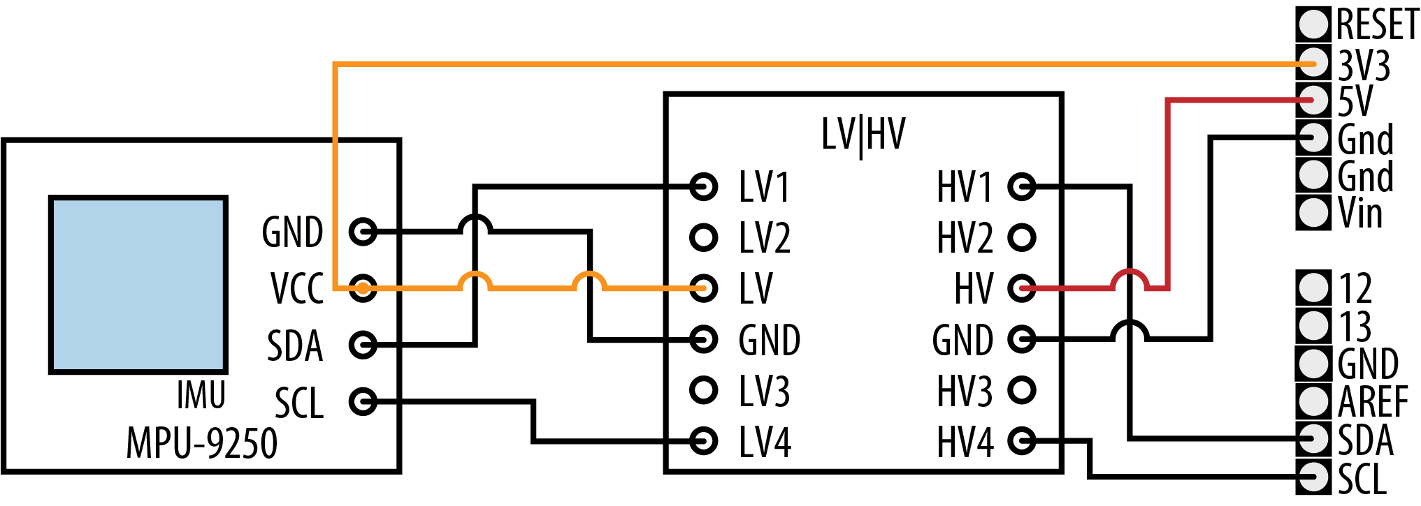
Using a 3.3V device with a logic-level translator
For a 3.3V I2C device, connect the LV side as follows:
-
LV1(A1 on the Adafruit board) pin to I2C SDA pin of the 3.3V device -
LV2(or A2) pin to I2C SCL pin of the 3.3V device -
LVpin to the 3.3V device’s VCC (power in) and a 3.3 volt power source such as the 3.3V pin on your Arduino board -
GNDpin to 3.3V device’s Gnd
Connect the HV (5V device, such as an Arduino Uno) side as follows:
-
HV1(or B1) pin to I2C SDA pin of the 5V device -
HV2(or B2) pin to I2C SCL pin of the 5V device -
HVpin to 5V device’s power pin, such as the 5V pin on your Arduino -
GNDpin Gnd on the 5V device
You can connect multiple I2C devices using a single logic-level translator, as in Figure 13-4.

Connecting multiple 3.3V and 5V I2C devices
For examples that would require a logic-level translator with 5V boards, see the recipes for the MPU-9250 in Recipe 6.15, Recipe 6.15, and Recipe 6.17.
SPI
The Arduino IDE includes a library that allows communication with SPI devices. SPI has separate input (labeled “MOSI”) and output (labeled “MISO”) lines and a clock line. These three lines are connected to the respective lines on one or more slaves/secondaries, which are identified by signaling with the Slave Select (SS) line, sometimes referred to as Chip Select (CS). Figure 13-5 shows the SPI connections.

Signal connections for SPI master and slaves
The pins to use for hardware SPI are shown in Table 13-1.
Some boards, such as SAMD-based boards like the Arduino Zero, Adafruit M0 Express, and SparkFun RedBoard Turbo, only expose hardware SPI via the ICSP header. Some 8-bit boards, such as the Leonardo, also require you to use the ICSP header. Figure 13-6 shows the connections. On those boards, you can use any digital pin (often pin 10) for SS/CS. But if you are using multiple SPI devices, you’ll need to assign a different digital pin for each devices SS/CS signal (SPI devices can share SCL, MISO, and MOSI).
| SPI signal | Arduino Uno | Arduino Mega |
|---|---|---|
|
SCLK (clock) |
13 |
52 |
|
MISO (data out) |
12 |
50 |
|
MOSI (data in) |
11 |
51 |
|
SS/CS (slave/chip select) |
10 |
53 |
Note
You may encounter some libraries that allow you to use a software SPI, which is similar in principle to software serial (“Emulate Serial Hardware with Digital Pins”) in that the SPI hardware is not used, and all the SPI operations are done in software. Like software serial, this will result in slower performance and may have some other limitations. But, if you are unable to use the hardware SPI pins for some reason, it can be very useful to have software SPI as an alternative. You can often tell when software SPI is available, because the library will have two forms of the constructor: one in which you pass only the SS/CS pin number (because the other three pins are determined by which Arduino-compatible board you use), and another in which you pass all four pins.
In some cases, such as the ST77xx color LCD (see Recipe 11.10), there is an additional pin, https://www.arduino.cc/en/reference/SPI, to toggle between data and command mode (The ST77xx also allows you to specify a reset pin in the constructor, but it is not part of the SPI protocol). So the hardware SPI version of the constructor is:
Adafruit_ST7735(TFT_CS, TFT_https://www.arduino.cc/en/reference/SPI, TFT_RST);
And the software SPI version looks like this:
Adafruit_ST7735(TFT_CS, TFT_https://www.arduino.cc/en/reference/SPI, TFT_MOSI, TFT_SCLK, TFT_RST);

SPI connections on the ICSP header
See Also
Applications note comparing I2C to SPI: https://www.maximintegrated.com/en/design/technical-documents/app-notes/4/4024.html
Arduino Wire library reference: http://www.arduino.cc/en/Reference/Wire
Arduino SPI library reference: https://www.arduino.cc/en/reference/SPI
13.1 Connecting Multiple I2C Devices
Problem
You want to connect more than one I2C device.
Solution
The following sketch uses an air quality sensor to measure the total volatile organic compound concentration (TVOC) in parts per billion and displays it on a 4-digit LED display. You must connect both the air quality sensor and the LED display controller over I2C. Figure 13-7 shows the wiring for those two I2C peripherals, as well as a four-digit LED segment display that’s connected to the LED controller.
/*
 * Two I2C Device sketch
 * Reads an air quality sensor and displays the VOC
 * concentration on an LED display.
 */

#include <Adafruit_CCS811.h>
#include <Adafruit_GFX.h>
#include <Adafruit_LEDBackpack.h>

// Create objects for the sensor and display.
Adafruit_CCS811 ccs;
Adafruit_7segment matrix = Adafruit_7segment();

void setup()
{
  Serial.begin(9600);
  if(!ccs.begin())
  {
    Serial.println("Could not start sensor.");
    while(1); // halt
  }
  while(!ccs.available()); // Wait until the sensor is ready

  matrix.begin(0x70); // Start the matrix

}

void loop()
{
  if(ccs.available())
  {
    if(!ccs.readData())
    {
      int tvoc = ccs.getTVOC(); // Get the VOC concentration
      matrix.println(tvoc);     // Write the value
      matrix.writeDisplay();    // Update the display
    }
  }
  delay(500);
}

Connections for air quality sensor and LED display
Discussion
The Solution uses two I2C components: the ams CCS811 air quality sensor, and the Holtek HT16K33 LED controller driver. Both of them are available on breakout boards from a variety of sources. Adafruit offers the air quality sensor as part number 3566 and the LED controller as part number 1427. SparkFun offers the air quality sensor as part number SEN-14193. The Solution uses the Adafruit board design and the Adafruit libraries (Adafruit CCS811 Library and Adafruit LED Backpack Library). You can install both libraries with the Arduino Library Manager.
When connecting more than one I2C device, you wire all the SDA lines together and all the SCL lines together. Each device connects to power and should have 0.1uF decoupling capacitors unless they are integrated into the breakout board (check the datasheet or schematic for the breakout board), as is the case with the sensor and LED controller driver. The GND lines must be connected together, even if the devices use separate power supplies (e.g., batteries).
Warning
If the breakout boards include the required pull-up resistors on the I2C lines (SCL and SDA), you may not need to include them in your circuit (see this chapter’s introduction). The Adafruit boards do include these, but if you are using another brand, you should check the datasheet or schematic.
The sketch initializes both devices in setup and repeatedly reads the TVOC concentration inside the loop, displaying the value on the LED display each time it gets a reading. Your LED display may have different pins, so be sure to consult the datasheet and adjust the wiring accordingly.
Both boards are 5V-tolerant, so you can use them with 5V boards. If you use the CCS811 with a 3.3V board, you must power it with 3.3V instead of 5V, otherwise the voltage on its I2C pins will be too high for your board. If you want to use the HT16K33 with a 3.3V board, it gets a little more complicated because, according to its spec, that board needs at least 4.5V to run. You could use a level converter with it (see “Using 3.3 Volt Devices with 5 Volt Boards”) with your 3.3V Arduino-compatible board as the low-voltage (LV) side, but some people have reported that it runs OK when powered at 3.3V, so you could try that first.
The HT16K33 expects a common cathode LED. The pinouts in Figure 13-7 are for a common 4-digit 7-segment display. A0 through A15 on the HT16K33 are used to control the seven segments as well as the decimal point. This sketch only uses A0 through A7. If you were using an LED matrix display, you would use more of the pins. Pins C0 through C7 select which digit to address. The HT16K33 rapidly switches between displaying each digit and relies on persistence of vision to make it appear that all four digits are illuminated at once.
Some of these displays have the ability to display a colon between each pair of digit, which is useful when you want to create a digital clock. The Adafruit LED backpack library assumes that this is connected to C4 (pin 4). But this sketch does not use it, so pin C4 is unused.
Under the hood, the Adafruit libraries use the Wire library to interact with the devices. For example, you could use matrix.setBrightness(1); to set the display to its lowest brightness (15 is the maximum). The library would issue these commands to accomplish that (0x70 is the I2C address of the HT16K33):
#define HT16K33_CMD_BRIGHTNESS 0xE0

Wire.beginTransmission(0x70);
Wire.write(HT16K33_CMD_BRIGHTNESS | 1);
Wire.endTransmission();
And when the sketch calls ccs.readData() followed by ccs.getTVOC(), the driver does something like this (0x5A is the I2C address of the CCS811). The TVOC reading is formed by combining the 3rd and 4th byte (remember, C arrays start at zero) into a word value:
  uint8_t buf[8];
  Wire.beginTransmission(0x5A);
  Wire.write(0x02); // Write to register 0x02
  Wire.endTransmission();

  Wire.requestFrom(0x5A, 8); // Request 8 bytes from the CCS811
  for(int i=0; i < 8; i++)
  {
    buf[i] = Wire.read();
  }
  int tvoc = word(buf[2], buf[3]);
See Also
Datasheet for the HT16K33: https://cdn-shop.adafruit.com/datasheets/ht16K33v110.pdf
Datasheet for the CCS811: https://cdn-learn.adafruit.com/assets/assets/000/044/636/original/CCS811_DS000459_2-00-1098798.pdf?1501602769
13.2 Connecting Multiple SPI Devices
Problem
You want to connect more than one SPI device.
Solution
This following sketch uses an SD Card reader to load bitmap images off an of an SD card. Those images are displayed on a TFT display. Both of them are SPI devices. Figure 13-8 shows the connections.
/*
 * Two SPI Device sketch
 * Loads all the bitmaps on the attached SD card
 * and displays them on a TFT screen.
 */

#include <Adafruit_GFX.h>
#include <Adafruit_ILI9341.h>
#include <SdFat.h>
#include <Adafruit_ImageReader.h>

#define SD_CS   4 // Chip select for SD reader
#define TFT_CS 10 // Chip select for TFT
#define TFT_DC  9 // Data/command pin for TFT
#define TFT_RST 8 // Reset pin for TFT

// Create the objects for each of the SPI devices
SdFat SD;
Adafruit_ILI9341 tft = Adafruit_ILI9341(TFT_CS, TFT_DC, TFT_RST);

SdFile root; // Root directory of SD card
Adafruit_ImageReader reader(SD); // Object to load and display images

void setup(void)
{
  Serial.begin(9600);
  if(!SD.begin(SD_CS, SD_SCK_MHZ(25))) // Start the SD card reader at 25MHz
  {
    Serial.println("Could not initialize SD card");
    while(1); // halt
  }

  tft.begin(); // Initialize the TFT

  if (!root.open("/"))
  {
    Serial.println("Could not read SD card directory");
    while(1); // halt
  }
}

void loop()
{
  ImageReturnCode rc; // Return code from image operations
  SdFile file; // Current file
  char filename[256]; // Buffer for filename

  while (file.openNext(&root, O_RDONLY)) // Find the next file on the SD card
  {
    file.getName(filename, sizeof(filename)/ sizeof(filename[0]));
    if(isBMP(filename)) // If it's a BMP, display it on the TFT
    {
      tft.fillScreen(0);
      rc = reader.drawBMP(filename, tft, 0, 0);
      delay(2000); // Pause
    }
    file.close();
  }
  root.rewind(); // Go back to the first file in the root directory
}

// Determins whether a file is a bitmap (BMP) file
int isBMP(char fname[])
{
  String fn = String(fname);
  fn.toLowerCase();
  return fn.endsWith("bmp");
}
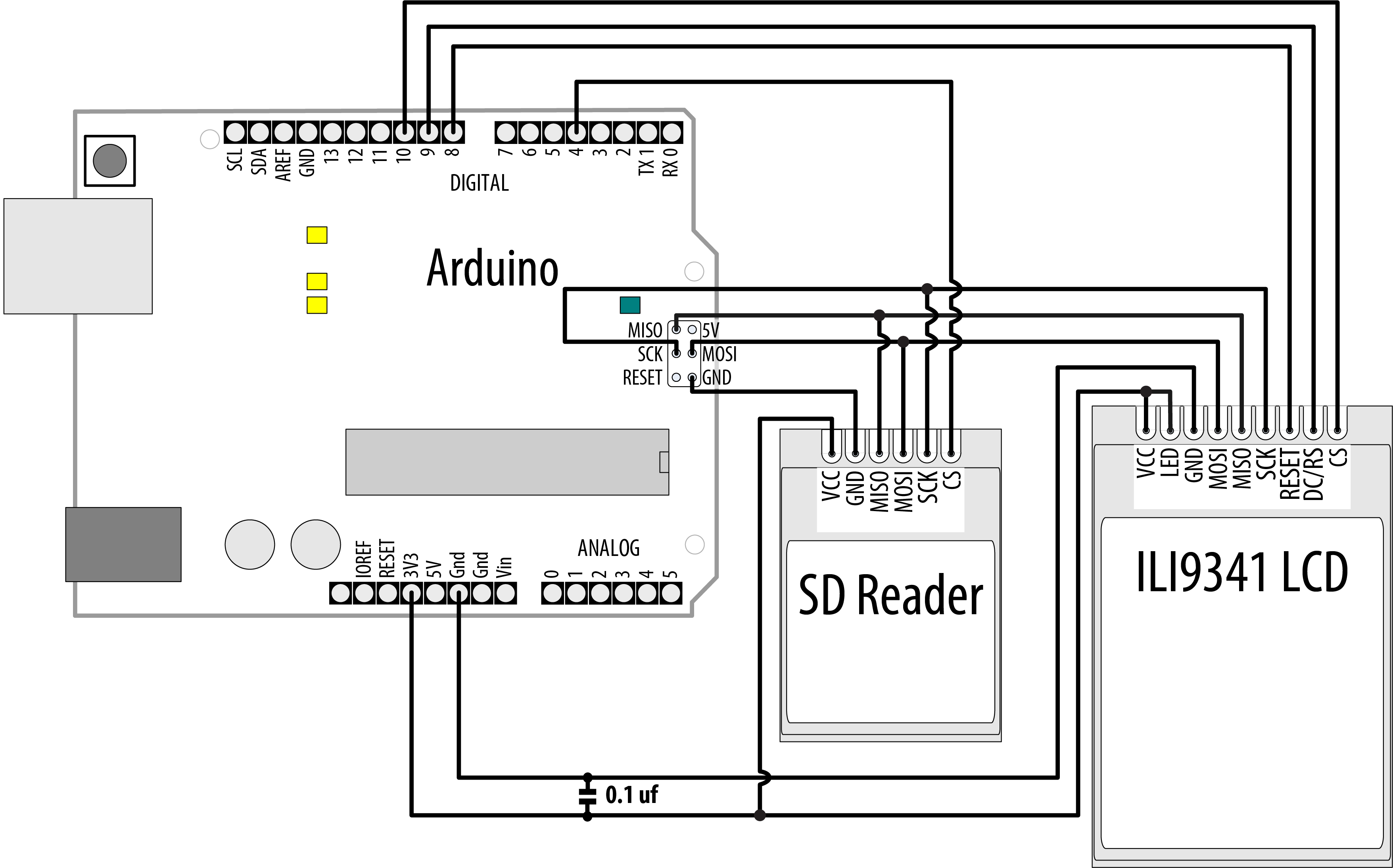
SPI connections for SD card reader and LCD panel
Discussion
The Solution uses an ILI9341-based TFT LCD display and an SD card reader breakout board, both of which are SPI devices. You can find both of these devices from a variety of vendors. In some cases, such as with Adafruit part number 1480, a microSD card reader is included on the TFT display breakout. In that case, you’ll have fewer connections to make because the LCD and SD card breakout share the MISO, MOSI, SCK, GND, and VIN pins.
The solution uses several libraries that you’ll need to install. Install the Adafruit GFX, Adafruit ILI9341, and Adafruit ImageReader libraries through the Arduino library manager. Although the Arduino IDE includes its own SD card library, the Adafruit ImageReader library, which is responsible for loading images from the card, uses a modified version of Bill Greiman’s SdFat library, which you can find by searching for “SdFat - Adafruit Fork” in the library manager.
Note
SD card readers come in a variety of forms. The simplest, such as SparkFun BOB-12941, are an SD card connector soldered to a breakout board. That’s possible because SD cards themselves can operate as SPI devices (you could, in a pinch, solder wires directly to the SD card). That type of reader can only operate at 3.3V. Some SD card readers, such as Adafruit part number 254, include a level shifter so you can power them with 5V and connect 5V logic pins to them.
With I2C, each device has a unique address. With SPI, each device has a chip select (CS) line that the library uses to signal that it wants to talk to that device. In the sketch, pin 4 is used as the chip select line for the SD card, and pin 10 is used for the TFT LCD display. There’s also a data/command pin that the Adafruit_ILI9341 library uses to talk to the display.
The sketch sets up a number of objects: one to represent the SD card, one for the TFT display, another to represent the root directory of the file system on the card, and an object that loads and displays images. In the setup function, the sketch initializes the SD card reader and TFT display, then opens the root directory for reading. Within loop, the sketch calls openNext() to get the next file, and uses the isBMP() function to decide whether the file is a bitmap. If it is, the sketch displays the bitmap on the screen before pausing and moving to the next.
The bitmap images must be saved as uncompressed BMP files, 24-bit color, or the sketch will be unable to load the images.
13.3 Working with an I2C Integrated Circuit
Problem
You want to use an I2C peripheral that comes in an integrated circuit package, such as a serial EEPROM. You would use such an EEPROM when you need more permanent data storage than Arduino has onboard, and you want to use an external memory chip to increase the capacity.
Solution
This recipe uses the 24LC128 I2C-enabled serial EEPROM from Microchip Technology. Figure 13-9 shows the connections. If you are using a 3.3V board, connect Vcc to 3.3V instead of 5V to avoid damaging your board.

I2C EEPROM connections
This recipe provides functionality similar to the Arduino EEPROM library (see Recipe 18.1), but it uses an external EEPROM connected using I2C to provide greatly increased storage capacity:
/*
 * I2C EEPROM sketch
 * Reads data from and writes data to an 24LC128
 */
#include <Wire.h>

const byte EEPROM_ID = 0x50; // I2C address for 24LC128 EEPROM

// first human-readable ASCII character '!' is number 33:
int thisByte = 33;

void setup()
{
  Serial.begin(9600);
  while(!Serial); // Required on Leonardo and most ARM-based boards
  Wire.begin();

  Serial.println("Writing 1024 bytes to EEPROM");
  for (int i=0; i < 1024; i++)
  {
    I2CEEPROM_Write(i, thisByte);
    // go on to the next character
    thisByte++;
    if (thisByte == 126)   // you could also use if (thisByte == '~')
      thisByte = 33;     // start over
  }

  Serial.println("Reading 1024 bytes from EEPROM");
  int thisByte = 33;
  for (int i=0; i < 1024; i++)
  {
    char c = I2CEEPROM_Read(i);
    if(c != thisByte)
    {
      Serial.println("read error");
      break;
    }
    else
    {
      Serial.print(c);
    }
    thisByte++;
    if(thisByte == 126)
    {
      Serial.println();
      thisByte = 33;     // start over on a new line
    }
  }
  Serial.println();
  Serial.println("Done.");
}

void loop()
{

}

// This function is similar to Arduino's EEPROM.write()
void I2CEEPROM_Write(unsigned int address, byte data)
{
  Wire.beginTransmission(EEPROM_ID);
  Wire.write((int)highByte(address));
  Wire.write((int)lowByte(address));
  Wire.write(data);
  Wire.endTransmission();

  delay(5); // wait for the I2C EEPROM to complete the write cycle
}

// This function is similar to EEPROM.read()
byte I2CEEPROM_Read(unsigned int address )
{
  byte data;

  Wire.beginTransmission(EEPROM_ID);
  Wire.write((int)highByte(address));
  Wire.write((int)lowByte(address));
  Wire.endTransmission();

  Wire.requestFrom(EEPROM_ID,(byte)1);
  while(Wire.available() == 0) // wait for data
    ;
  data = Wire.read();
  return data;
}
Discussion
This recipe shows the 24LC128, which has 128K of memory; although there are similar chips with higher and lower capacities (the Microchip link in this recipe’s See Also section has a cross-reference). The chip’s address is set using the three pins marked A0 through A2 and is in the range 0x50 to 0x57, as shown in Table 13-2.
| A0 | A1 | A2 | Address |
|---|---|---|---|
|
Gnd |
Gnd |
Gnd |
0x50 |
|
+5V |
Gnd |
Gnd |
0x51 |
|
Gnd |
+5V |
Gnd |
0x52 |
|
+5V |
+5V |
Gnd |
0x53 |
|
Gnd |
Gnd |
+5V |
0x54 |
|
+5V |
Gnd |
+5V |
0x55 |
|
+5V |
+5V |
Gnd |
0x56 |
|
+5V |
+5V |
+5V |
0x57 |
Use of the Wire library in this recipe is similar to its use in other recipes in this chapter, so read through those for an explanation of the code that initializes and requests data from an I2C device.
The write and read operations that are specific to the EEPROM are contained in the functions i2cEEPROM_Write and i2cEEPROM_Read. These operations start with a Wire.beginTransmission to the device’s I2C address. This is followed by a 2-byte value indicating the memory location for the read or write operation. In the write function, the address is followed by the data to be written—in this example, one byte is written to the memory location.
The read operation sends a memory location to the EEPROM, which is followed by Wire.requestFrom(EEPROM_ID,(byte)1);. This returns one byte of data from the memory at the address just set.
If you need to speed up writes, you can replace the 5 ms delay with a status check to determine if the EEPROM is ready to write a new byte. See the “Acknowledge Polling” technique described in Section 7 of the datasheet. You can also write data in pages of 64 bytes rather than individually; details are in Section 6 of the datasheet.
The chip remembers the address it is given and will move to the next sequential address each time a read or write is performed. If you are reading more than a single byte, you can set the start address and then perform multiple requests and receives.
Note
The Wire library can read or write up to 32 bytes in a single request. Attempting to read or write more than this can result in bytes being discarded.
The pin marked WP is for setting write protection. It is connected to ground in the circuit here to enable the Arduino to write to memory. Connecting it to 5V prevents any writes from taking place. This could be used to write persistent data to memory and then prevent it from being overwritten accidentally.
See Also
The 24LC128 datasheet: http://ww1.microchip.com/downloads/en/devicedoc/21191n.pdf
If you need to speed up writes, you can replace the 5 ms delay with a status check to determine if the EEPROM is ready to write a new byte. See the “Acknowledge Polling” technique described in Section 7 of the datasheet.
A cross-reference of similar I2C EEPROMs with a wide range of capacities is available at http://ww1.microchip.com/downloads/en/DeviceDoc/21621d.pdf.
A shield is available that combines reading temperature, storing in EEPROM, and 7-segment display: http://store.gravitech.us/7segmentshield.html.
13.4 Increase IO with an I2C Port Expander
Problem
You want to use more input/output ports than your board provides.
Solution
You can use an external port expander, such as the PCF8574 or PCF8574A, which have eight input/output pins that can be controlled using I2C. The sketch creates a bar graph with eight LEDs. Figure 13-10 shows the connections.
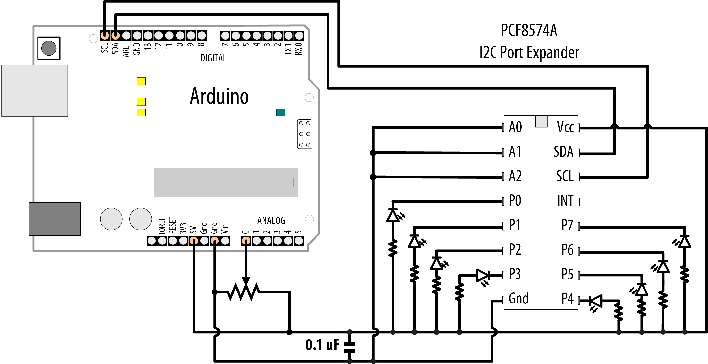
PCF8574/A port expander driving eight LEDs
Warning
If you are using a 3.3V board, connect Vcc to 3.3V instead of 5V to avoid damaging your board.
The sketch has the same functionality as described in Recipe 7.6, but it uses the I2C port expander to drive the LEDs so that only two pins are required:
/*
 * I2C bargraph sketch
 * Uses I2C port to drive a bar graph
 * Turns on a series of LEDs proportional to a value of an analog sensor.
 * see Recipe 7.6
 */

#include <Wire.h>

const int address = 0x20; // PCF8574 address; use 0x38 for PCF8574A
const int NbrLEDs = 8;

const int analogInPin = A0; // Analog input pin connected
                            // to a variable resistor

int sensorValue = 0;    // value read from the sensor
int ledLevel = 0;       // sensor value converted into LED 'bars'
int ledBits = 0;        //  bits for each LED will be set to 1 to turn on LED

void setup()
{
  Wire.begin(); // set up Arduino I2C support
}

void loop()
{
  sensorValue = analogRead(analogInPin);             // read the analog value
  ledLevel = map(sensorValue, 0, 1023, 0, NbrLEDs);  // map to number of LEDs
  for (int led = 0; led < NbrLEDs; led++)
  {
    Wire.beginTransmission(address);
    if (led < ledLevel)
    {
      Wire.write(~ (1 << led));
    }
    else
    {
      Wire.write(0xFF); // Turn off all LEDs
    }
    Wire.endTransmission(); // send the value to I2C
  }
}
Discussion
The resistors should be 220 ohms or more (see Chapter 7 for information on selecting resistors).
The sketch reads a value from analogRead, then maps it to a value (ledLevel) between zero to the number of LEDs. Then the sketch goes into a for loop that iterates over each LED. If the LED’s number is less than ledLevel, then the sketch illuminates that LED. The command to activate a pin on the PCF8574/A is a bitfield: 0b00000001 (1) would take pin 0 high, and 0b11111111 (255) would take all the pins high. However, you don’t want to take a pin high to illuminate an LED with the PCF8574/A!
The PCF8574/A has a lower capacity for driving LEDs than Arduino. Each pin can only provide (source) a miniscule amount of current, far less than would be needed to power an LED. However, each pin can receive (sink) up to 25mA. This means that you must use inverted logic, similar to the INPUT_PULLUP mode (see Recipe 2.4), with the PCF8574/A. This is why each LED is tied to +5V/+3.3V instead of to GND: when one of the pins goes LOW, current is sourced from the positive power supply, and the pin sinks that current. This is why the sketch uses the boolean not operator, ~, to invert the value (so 0b00000001, or 1 decimal, becomes 0b11111110, or 254 decimal).
Further, there is an additional limit: the PCF8574/A cannot sink more than 80mA at one time. So if you were to turn all the LEDs on (0b00000000), it would probably work, but you’d exceed the limits of the chip, shortening its life. This is why the sketch only turns on one LED at a time by using boolean shift left to calculate a bitfield where only that pin is enabled, and then inverting it. You would turn on pin 0 with 0b11111110, and pin 3 with 0b11110111. This happens rapidly enough that, thanks to persistence of vision, it appears that multiple lights are illuminated at once. Although it is not strictly necessary to issue the Wire.write(0xFF); when encountering an LED that is not illuminated, doing so ensures that the sketch always performs the same number of commands, which keeps the LEDs at a consistent brightness regardless of how many are illuminated.
If you want to minimize flicker while still staying within the limits of the PCF8574/A, you can illuminate four LEDs at a time:
  int bitField = 0;
  for (int led = 0; led < NbrLEDs; led++)
  {
    if (led < ledLevel)
    {
      bitField |= (1 << led);
    }
    if ((led + 1) % 4 == 0) // Send a command every four pins
    {
      Wire.beginTransmission(address);
      Wire.write(~bitField);
      Wire.endTransmission(); // send the value to I2C
      bitField = 0; // clear the bitfield
    }
  }
You can change the address by changing the connections of the pins marked A0, A1, and A2, as shown in Table 13-3. If you are using a PCF8574/A breakout board, it should have jumpers or solder pads for selecting the address.
| A0 | A1 | A2 | PCF8574A Address | PCF8574 Address |
|---|---|---|---|---|
|
Gnd |
Gnd |
Gnd |
0x38 |
0x20 |
|
+5V |
Gnd |
Gnd |
0x39 |
0x21 |
|
Gnd |
+5V |
Gnd |
0x3A |
0x22 |
|
+5V |
+5V |
Gnd |
0x3B |
0x23 |
|
Gnd |
Gnd |
+5V |
0x3C |
0x24 |
|
+5V |
Gnd |
+5V |
0x3D |
0x25 |
|
+5V |
+5V |
Gnd |
0x3E |
0x26 |
|
+5V |
+5V |
+5V |
0x3F |
0x27 |
To use the port expander for input, read a byte from the expander as follows:
  Wire.requestFrom(address, 1);
  if(Wire.available())
  {
    data = Wire.receive();
    Serial.println(data,BIN);
  }
See Also
PCF8574/A data sheet: https://www.nxp.com/docs/en/data-sheet/PCF8574_PCF8574A.pdf
If you need a solution that can handle more current, see Recipe 13.1.
13.5 Communicating Between Two or More Arduino Boards
Problem
You want to have two or more Arduino boards working together. You may want to increase the I/O capability or perform more processing than can be achieved on a single board. You can use I2C to pass data between boards so that they can share the workload.
Solution
The two sketches in this recipe show how I2C can be used as a communications link between two or more Arduino boards. Figure 13-11 shows the connections.
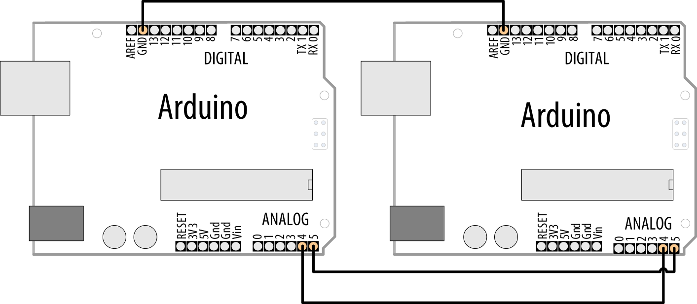
Arduino as I2C master and slave/secondary
The master sends characters received on the serial port to an Arduino secondary using I2C:
/*
 * I2C Master sketch
 * Echo Serial data to an I2C secondary
 */

#include <Wire.h>

const int address = 4;  // the address to be used by the communicating devices

void setup()
{
  Wire.begin();
  Serial.begin(9600);
}

void loop()
{
  char c;
  if(Serial.available() > 0)
  {
    c = Serial.read();
    // send the data
    Wire.beginTransmission(address); // transmit to device
    Wire.write(c);
    Wire.endTransmission();
  }
}
The other Arduino prints characters received over I2C to its serial port:
/*
 * I2C Secondary sketch
 * monitors I2C requests and echoes these to the serial port
 */

#include <Wire.h>

const int address = 4;  // the address to be used by the communicating devices

void setup()
{
  Serial.begin(9600);
  Wire.begin(address); // join I2C bus using this address
  Wire.onReceive(receiveEvent); // register event to handle requests
}

void loop()
{
  // nothing here--all the work is done in receiveEvent
}

void receiveEvent(int howMany)
{
  while(Wire.available() > 0)
  {
    char c = Wire.read(); // receive byte as a character
    Serial.write(c); // echo
  }
}
Discussion
This chapter focused on Arduino as the I2C master accessing various I2C secondary devices. Here a second Arduino acts as an I2C secondary that responds to requests from another Arduino. Techniques covered in Chapter 4 for sending bytes of data can be applied here. For example, you can send data using the print method.
The following sketch sends its output over I2C using Wire.println. Using this with the I2C secondary sketch shown previously enables you to print data from the master without using the serial port (the secondary’s serial port is used to display the output):
/*
 * I2C Master w/print sketch
 * Sends sensor data to an I2C secondary using print
 */

#include <Wire.h>

const int address = 4;     // the address to be used by the communicating devices
const int sensorPin = A0;  // select the analog input pin for the sensor
int val;                   // variable to store the sensor value

void setup()
{
  Wire.begin();
}

void loop()
{
  val = analogRead(sensorPin);       // read the voltage on the pot
                                     // (val ranges from 0 to 1023)
  Wire.beginTransmission(address); // transmit to device
  Wire.println(val);
  Wire.endTransmission();
  delay(1000);
}
The next example handles multiple values as described in Recipe 4.5 over i2c instead of Serial.
This sketch will send the values of the first three analog pins in a text message of the form: H3,v0,v1,v2 where ‘H’ is a character indicating the start of the message followed by the number 3 indicates that in this example there will be three values in the message. v0,v1,v2 will be the numeric values of the three analog inputs.
/** I2C Master multiple sketch* Sends multiple sensor data to an I2C secondary using print*/#include <Wire.h>constintaddress=4;// address for the communicating devicesconstintfirstSensorPin=A0;// first input pin of sequenceconstintnbrSensors=3;// three sequential pins will be usedintval;// variable to store the sensor valuevoidsetup(){Wire.begin();Serial.begin(9600);}voidloop(){Wire.beginTransmission(address);// transmit to deviceWire.('H');// header indicating start of a messageWire.(nbrSensors);for(inti=0;i<nbrSensors;i++){val=analogRead(firstSensorPin+1);// read the sensorWire.(',');// comma separatorWire.(val);}Wire.println();// end of messageWire.endTransmission();delay(100);}
This sketch handles the messages sent by the previous sketch and prints the values to the serial monitor.
/** I2C Secondary multiple sketch* monitors I2C requests and echoes these to the serial port*/#include <Wire.h>constintaddress=4;//address used by the communicating devicesvoidsetup(){Serial.begin(9600);Wire.begin(address);// join I2C bus using this addressWire.onReceive(receiveEvent);// register event to handle requests}voidloop(){// nothing here, all the work is done in receiveEvent}voidreceiveEvent(inthowMany){while(Wire.available()>0){charc=Wire.read();// receive byte as a characterif(c=='H'){// here if start of messageintnbrSensors=Wire.parseInt();if(nbrSensors>0){for(inti=0;i<nbrSensors;i++){intval=Wire.parseInt();Serial.(val);Serial.(" ");}Serial.println();}}}}
See Also
Chapter 4 has more information on using the Arduino print functionality.
13.6 Using the Wii Nunchuck Accelerometer
Problem
You want to connect a Wii nunchuck to your Arduino as a convenient and fun way to use accelerometer input. The nunchuck is a popular low-cost game device that can be used to indicate the orientation of the device by measuring the effects of gravity. You can use either an original Wii nunchuck, or find a third-party clone (which will usually be much cheaper).
Solution
The nunchuck uses a proprietary plug. If you don’t need to use your nunchuck with your Wii again, you can cut the lead to connect it. Alternatively, it is possible to use a small piece of matrix board to make the connections in the plug if you are careful (the pinouts are shown in Figure 13-12) or you can buy an adapter such as the NunChucky Wii Nunchuck I2C Breakout from Solarbotics (part number 31040).

Connecting a nunchuck to Arduino
Note
Adapters like the NunChucky assume you are using an Arduino board where SDA is available on pin A4 and SCL is available on pin A5. This is true for Arduino Uno and most boards based on the ATmega328 (and earlier chips such as the ATmega168). But it is not true for ARM-based Arduino boards, the Leonardo, and many others. If you are using such a board, or if you are using a board with a layout different than the Uno, you should wire the adapter’s SDA and SCL pins to the corresponding pins on your board, and provide power and ground from the board’s 3.3V and GND pins. If you do this, you can remove the lines of code that set gndPin LOW and vccPin HIGH.
/*
 * nunchuck_lines sketch
 * sends data to Processing to draw line that follows nunchuck movement
 */

#include <Wire.h> // initialize wire

const int vccPin = A3;   // +v provided by pin 17
const int gndPin = A2;   // gnd provided by pin 16

const int dataLength = 6;          // number of bytes to request
static byte rawData[dataLength];   // array to store nunchuck data

enum nunchuckItems { joyX, joyY, accelX, accelY, accelZ, btnZ, btnC };

void setup() {
  pinMode(gndPin, OUTPUT); // set power pins to the correct state
  pinMode(vccPin, OUTPUT);
  digitalWrite(gndPin, LOW);
  digitalWrite(vccPin, HIGH);
  delay(100);  // wait for things to stabilize

  Serial.begin(9600);
  nunchuckInit();
}

void loop(){
  nunchuckRead();
  int acceleration = getValue(accelX);
  if((acceleration >= 75) && (acceleration <= 185))
  {
    //map returns a value from 0 to 63 for values from 75 to 185
    byte  x = map(acceleration, 75, 185, 0, 63);
    Serial.write(x);
  delay(20); // the time in milliseconds between redraws
  }
}

void nunchuckInit(){
  Wire.begin();                // join i2c bus as master
  Wire.beginTransmission(0x52);// transmit to device 0x52
  Wire.write((byte)0x40);      // sends memory address
  Wire.write((byte)0x00);      // sends sent a zero.
  Wire.endTransmission();      // stop transmitting
}

// Send a request for data to the nunchuck
static void nunchuckRequest(){
  Wire.beginTransmission(0x52);// transmit to device 0x52
  Wire.write((byte)0x00);      // sends one byte
  Wire.endTransmission();      // stop transmitting
}

// Receive data back from the nunchuck,
// returns true if read successful, else false
bool nunchuckRead(){
  int cnt=0;
  Wire.requestFrom (0x52, dataLength); // request data from nunchuck
  while (Wire.available ()) {
    rawData[cnt] = nunchuckDecode(Wire.read());
    cnt++;
  }
  nunchuckRequest();  // send request for next data payload
  if (cnt >= dataLength)
    return true;     // success if all 6 bytes received
  else
    return false;    //failure
}

// Encode data to format that most wiimote drivers accept
static char nunchuckDecode (byte x) {
  return (x ^ 0x17) + 0x17;
}

int getValue(int item){
  if (item <= accelZ)
    return (int)rawData[item];
  else if (item  == btnZ)
    return bitRead(rawData[5], 0) ? 0: 1;
  else if (item  == btnC)
    return bitRead(rawData[5], 1) ? 0: 1;
}
Discussion
I2C is often used in commercial products such as the nunchuck for communication between devices. There are no official datasheets for this device, but the nunchuck signaling was analyzed (reverse engineered) to determine the commands needed to communicate with it.
You can use the following Processing sketch to display a line that follows the nunchuck movement, as shown in Figure 13-13 (see Chapter 4 for more on using Processing to receive Arduino serial data; also see Chapter 4 for advice on setting up and using Processing with Arduino):
 // Processing sketch to draw line that follows nunchuck data

import processing.serial.*;

Serial myPort;  // Create object from Serial class
public static final short portIndex = 1;

void setup()
{
  size(200, 200);
  // Open whatever port is the one you're using - See Chapter 4
  myPort = new Serial(this,Serial.list()[portIndex], 9600);
}

void draw()
{
  if ( myPort.available() > 0) {  // If data is available,
    int y = myPort.read();        // read it and store it in val
    background(255);              // Set background to white
    line(0,63-y,127,y);           // draw the line
  }
}

Nunchuck movement represented by tilted line in Processing
The sketch includes the Wire library for I2C communication and defines the pins used to power the nunchuck:
#include <Wire.h> // initialize wire

const int vccPin = A3;   // +v (vcc) provided by pin 17
const int gndPin = A2;   // gnd provided by pin 16
Wire.h is the I2C library that is included with the Arduino release. A3 is analog pin 3 (digital pin 17), A2 is analog pin 2 (digital pin 16); these pins provide power to the nunchuck.
enum nunchuckItems { joyX, joyY, accelX, accelY, accelZ, btnZ, btnC };
enum is the construct to create an enumerated list of constants, in this case a list of the sensor values returned from the nunchuck. These constants are used to identify requests for one of the nunchuck sensor values.
setup initializes the pins used to power the nunchuck by setting the vccPin HIGH and gndPin LOW. This is only needed if the nunchuck adapter is providing the power source. Using digital pins as a power source is not usually recommended, unless you are certain, as with the nunchuck, that the device being powered will not exceed a pin’s maximum current capability (40 mA; see Chapter 5).
The function nunchuckInit establishes I2C communication with the nunchuck.
I2C communication starts with Wire.begin(). In this example, Arduino as the master is responsible for initializing the desired slave/secondary device, the nunchuck, on address 0x52.
The following line tells the Wire library to prepare to send a message to the device at hexadecimal address 52 (0x52):
beginTransmission(0x52);
Note
I2C documentation typically shows addresses with hexadecimal values, so it’s convenient to use this notation in your sketch.
Wire.send puts the given values into a buffer within the Wire library where data is stored until Wire.endTransmission is called to actually do the sending.
nunchuckRequest and nunchuckRead are used to request and read data from the nunchuck:
This Wire library requestFrom function is used to get six bytes of data from device 0x52 (the nunchuck).
The nunchuck returns its data using six bytes as follows:
| Byte number | Description |
|---|---|
|
Byte 1 |
x-axis analog joystick value |
|
Byte 2 |
y-axis analog joystick value |
|
Byte 3 |
x-axis acceleration value |
|
Byte 4 |
y-axis acceleration value |
|
Byte 5 |
z-axis acceleration value |
|
Byte 6 |
Button states and least significant bits of acceleration |
Wire.available works like Serial.available (see Chapter 4) to indicate how many bytes have been received, but over the I2C interface rather than the serial interface. If data is available, it is read using Wire.read and then decoded using nunchuckDecode. Decoding is required to convert the values sent into numbers that are usable by your sketch, and these are stored in a buffer (named rawData). A request is sent for the next six bytes of data so that it will be ready and waiting for the next call to get data:
int acceleration = getValue(accelX);
The function getValue is passed one of the constants from the enumerated list of sensors, in this case the item accelX for acceleration in the x-axis.
You can send additional fields by separating them using commas (see Recipe 4.4); here is the revised loop function to achieve this:
void loop(){
  nunchuckRead();
  Serial.print("H,"); // header
  for(int i=0; i < 3; i++)
  {
     Serial.print(getValue(accelX+ i), DEC);
     if( i > 2)
        Serial.write(',');
     else
        Serial.write('
')  ;
  }
  delay(20); // the time in milliseconds between redraws
}
See Also
See Recipe 16.5 for a library for interfacing with the nunchuck, and the Discussion of Recipe 4.4 for a Processing sketch that displays a real-time bar chart showing each of the nunchuck values.