Chapter 6 Configuring and Securing the 6500/7600 Chassis
The FWSM isn’t just a Power Sucking Alien (PSA) in the 6500/7600 chassis (host-chassis), it plays a critical role in the overall solution to securing your infrastructure. Proper “care and feeding” of the host-chassis is paramount, and following the best practices in this chapter will help to minimize a potential compromise of your network.
Understanding the Interaction Between the Host-Chassis and the FWSM
With the integration of the FWSM in a host-chassis, it becomes imperative to secure the host device. This is because the delineation of interfaces on the FWSM is associated with the virtual local-area network (VLAN) interfaces of the switch. The separation is logical not physical. If a misconfiguration occurs on the switch, traffic from a less secure interface (outside) may have uninhibited access to a more secure interface (inside). For this reason, you must consider the switch configuration and access to the host-chassis as critical as the FWSM configuration and access to the FWSM.
The host-chassis provides power and connectivity for the FWSM. In Chapter 2, “Overview of the Firewall Services Module,” you learned that the FWSM is connected to the backplane of the host-chassis through a full-duplex 6-gigabit EtherChannel (GEC) connection and consumes 171.78 watts of power. The GEC is the communication mechanism between the two devices. Consider the host-chassis as an extension of the FWSM through the use of VLANs. VLANs from the host-chassis are assigned to the FWSM, and a Layer 2 connection is established across the GEC. Figure 6-1 shows a logical representation of how the FWSM connects to VLANs within the host-chassis.
Figure 6-1FWSM/Host-Chassis Overview
As you can see from Figure 6-1, VLANs are logically associated to the FWSM, but all traffic traversing the FWSM must use the GEC for ingress and egress flows. This configuration could also be considered a FWSM on a stick.

The VLAN can then be associated to a Switched Virtual Interface (SVI) or routed interface on the Multilayer Switch Feature Card (MSFC), as shown in Figure 6-2. This interface has the IP address assignment and would act as the next-hop address.
Figure 6-2Switched Virtual Interface

By default, you can assign only one FWSM VLAN to an SVI. This is to prevent you from bypassing the FWSM and routing across the MSFC. The MSFC is the Layer 3 device on the host-chassis that handles routing. If it becomes necessary to bypass the firewall, use the firewall multiple-vlan-interfaces command in configuration mode. When entering this command, you will be greeted with the following message:
host-chassis(config)# firewall multiple-vlan-interfaces
Warning: enabling multiple VLAN interfaces may result in traffic bypassing the FWSM - use with caution!
WARNING | Heed the warning! Bypassing the FWSM may not be the intended result you are looking for. |
When the multiple-vlan-interfaces feature is configured, traffic may have an alternative path between networks using the MSFC. This would circumvent any security policies that are applied on the FWSM.
Figure 6-3 illustrates how the traffic flowing between the two clients bypasses the FWSM.
6-3FWSM Bypass
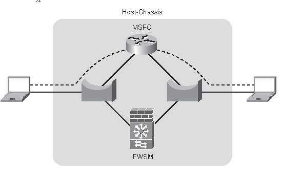
This configuration may be used to direct Novell Internetwork Packet Exchange (IPX) traffic, specific applications, or hosts through the MSFC. This can be accomplished by using Policy Based Routing (PBR), essentially creating a rule set that matches specific traffic and sends that traffic through another path. For additional information on PBR, take a look at the Cisco Press book Routing TCP/IP, Volume I.
If you take a holistic view of the FWSM and the host-chassis together, and consider them a “single” unit, it will provide you with a better understanding of how to secure your infrastructure. Remember that you can take advantage of the routing resources of the MSFC, bridging capabilities of the VLANs and the FWSM
Assigning Interfaces
For the FWSM to communicate to other devices on the network, a connection must be made from logical interfaces of the FWSM to VLANs assigned to the host-chassis.
Referring to Figure 6-3, notice that the FWSM is logically connected to VLANs. This is accomplished through the following process.
To assign VLAN interfaces to the FWSM, see Chapter 7, “Configuring the FWSM.”
The host-chassis provides a great deal of flexibility in how the FWSM communicates with the outside world. As you consider how to implement the FWSM in your network, be sure to take advantage of the routing and switching capabilities of the host-chassis.
Securing the 6500/7600 (Host-Chassis)
The following section is intended to give you an overview of the features that need to be deployed to ensure a secure infrastructure. It is beyond the scope of this book to provide an in-depth understanding of each feature. You should refer to the appropriate switch/router documentation for specific details. The National Security Agency (NSA) has a guide to securing routers that would be a good place to start (http://www.nsa.gov/snac/routers/cisco_scg-1.1b.pdf).
You can secure the host-chassis in several ways, including the following:
• Controlling Physical Access
• Being Mindful of Environmental Considerations
• Controlling Management Access
• Disabling Unnecessary Services
• Controlling Access Using Port-Based Security
• Controlling Spanning Tree
• Leveraging Access Control Lists
• Securing Layer 3
• Leveraging Control Plane Policing
• Protecting a Network Using Quality of Service
Controlling Physical Access
Anyone with physical access to the equipment has the ability to quickly perform a Denial of Service (DoS) attack by turning off the power, moving cables, removing line cards, and so on. It is critical to restrict access to individuals who cannot be trusted to behave appropriately.
Equipment can be protected inside locked cabinets, equipment rooms with controlled access by using badge readers or keys, and securing physical cabling within conduit. Other mechanisms that may detour inappropriate activity are closed-circuit TV, motion detectors, lighting, and so on.
If a physical attack occurs and you need to recover, having current documentation of the network, physical connectivity information, and up-to-date configurations of the equipment will significantly help in rebuilding your infrastructure.
Being Mindful of Environmental Considerations
Although not directly related to security, proper heating, cooling, air cleanliness, and conditioned power play a significant role in the availability of the equipment. If the equipment is not working because of the environment, then there is no need to worry about good security. For more information on some of the environmental considerations for the FWSM and the appropriate documentation for the host-chassis, see Chapter 2.
• Be certain that the equipment operates well within the listed specifications for heating and cooling: For example, if your 6500/7600 is located in a data center, you may consider using a chassis that has front to rear airflow.
• Maintain a clean datacenter or server room: If the host-chassis is in a location without appropriate filtering, dust, chemicals, or debris may enter and cause problems with the electronics.
• Ensure that voltage and/or current levels are stable: Fluctuations in voltage and/or current either above or below the recommended levels may also cause some interesting side effects, causing a service outage. Use an appropriate Uninterruptible Power Supply (UPS) and/or line conditioner to control voltage/current levels.
When protecting services that you are offering to consumers, it’s not just about firewall rules. You need to consider all factors and manage the risks accordingly.
Controlling Management Access
Methods for accessing the FWSM, include Telnet, Secure Shell (SSH), direct console access, access from the host-chassis, and Hypertext Transfer Protocol over Secure Sockets layer (HTTPS). If someone with malicious intent were to gain access to the FWSM using any of these methods, they could potentially gain unfiltered access to resources within your network. Access methods need to be highly controlled. This becomes even more significant when numerous individuals are accessing the same equipment.
Mechanisms using authorization, authentication, and accounting leveraging a central policy server, such as Terminal Access Controller Access Control Server+ (TACACS+) or Remote Authentication Dial-In User Service (RADIUS), reduce the overhead in managing local users on individual devices and allow an administrator to quickly modify privileges of users from a single location.
TIP | Secure Shell Version 1 (SSH) has vulnerabilities and should never be used to manage devices. Use SSHv2 instead. |
Remote access protocols that include encryption, such as SSHv2 and HTTPS, minimize the possibility of eavesdropping; using those in conjunction with One Time Passwords (OTP) considerably help protect remote access to the device.
Simple Network Management Protocol (SNMP) versions 1 and 2 provide weak security and should be avoided if possible. SNMP version 3 adds security mechanisms, such as message integrity, authentication, and encryption, and provides a more secure mechanism for management. Other precautions should also be taken, such as the following:
• Use SNMP for read-only access, not write access on the host-chassis. The FWSM does not allow write access.
• Use very complex passwords that are device specific.
• Use an access list on the SNMP-server community attribute to allow only specific management devices.
• Monitor authentication-failure violations.
• Change the password often!
TIP | Complex or secure passwords contain combinations of special characters—for example, “! % & } ~ @” and so on, in addition to letters and numbers. The password should be at least eight characters in length and preferably more. Passwords should also not be a word or name, and you should avoid using numeric or special-character substitutions—for example, “cisco” to “c1$c0”. |
Login banners do not provide any type of security, but they may assist a potential attacker in gathering information about your organization. Avoid displaying company information or phone numbers, using a welcoming comment, or providing any information that would benefit would-be attackers or make them think it is permissible to access your device. Using a message that indicates that unauthorized access is prohibited, that access to this is monitored, and that unlawful use of this device may result in legal action may help your case in the event of malicious use.
HTTP and HTTPS should also be disabled unless necessary. In that event, use HTTPS with an access class allowing only specific devices; use an authentication, authorization, and accounting (AAA) server for authentication, limit the number of connections, and use a nonstandard port for access.
Use SSHv2 for remote access with an AAA server for authentication whenever possible. SSH incorporates authentication and encryption and provides a secure mechanism for access to the device. If you use SSH exclusively, configure the Virtual Terminal (VTY) lines to permit only SSH connections with the transport input ssh command. This will provide an extra measure of security; remember “defense in depth”!
You can use several methods to manage the host-chassis and/or the FWSM. The primary concern is to make sure only authorized individuals can gain access by using the most secure communication mechanisms and strong passwords. You should also be familiar with the command-line interface (CLI) using SSHv2 in the event other methods are not available.
Disabling Unnecessary Services
The following services may not be needed. Before you make any changes to a “live” network, be sure you know what the results will be.
• Cisco Discovery Protocol (CDP) is a Layer 2 protocol that is used to provide information about other CDP devices that are directly attached. It is a tremendous tool for troubleshooting but should be disabled on interfaces that have only host devices attached.
• Finger is used to gather information about users logged into a host and is rarely used on an IOS-based device.
• Internet Control Message Protocol (ICMP) redirects are used to tell a device to use a different router to reach the destination. If you have subnets with a single router or routers using Hot Standby Routing Protocol (HSRP), Virtual Router Redundancy Protocol (VRRP), or Gateway Load Balancing Protocol (GLBP), you can potentially disable ICMP redirects.
• ICMP unreachables are sent to the source in the event of a dropped packet. This is generally unnecessary and may overwhelm a switch or router.
• IP BOOTP (Internet Protocol Bootstrap Protocol) server is typically not a service used and should be disabled.
• IP source routing allows the sender to dictate the path that traffic will take to the destination. This function is generally used with malicious intent and should also be disabled.
• Internet Protocol version 6 (IPv6) may open additional vulnerabilities and can be turned off if not in use.
• Network Time Protocol (NTP) should be configured specifically for a time source and should be authenticated, otherwise disable the service.
• Packet Assembler/Disassembler (PAD), unless you are running X.25 and know what PAD is, it should be turned off.
• Proxy Address Resolution Protocol (ARP) is a function in which the router replies to local ARP requests from the source on behalf of the destination. This is generally not a good practice and measures should be taken to eliminate this function.
• Transmission Control Protocol (TCP) and User Datagram Protocol (UDP) small services, including echo, chargen (character generator), and discard should also be disabled.
• Trivial File Transfer Protocol (TFTP) server should be used only on a temporary basis and should be disabled after use.
Often, services may be running on the host-chassis that are completely unnecessary. These services could potentially allow unauthorized access to the device or provide an avenue for someone with malicious intent to create a DoS attack. For the best possible protection, turn off unused services.
Controlling Access Using Port-Based Security
Vendors, partners, consultants, employees, and so on bringing in unauthorized devices might need access to resources on your network or to use your network as a transit to the Internet. These individuals may not always be inclined to ask permission before making a connecting to your network. If they have an opportunity to connect, there is a potential to spread malicious software (malware), either intentionally or unintentionally, and/or allow them the opportunity for other harmful activities.
Controlling which devices that are authorized to have access and those that are not can be a significant concern. Several mechanisms provide the capability to automatically authenticate a device and/or user access to the network. Some of these include Network Admission Control (NAC), 802.1x, MAC-based authentication, web-based proxy authentication, and so on. If you are doing this manually, be sure to turn off 802.1Q trunking to client devices. Doing so will minimize any impact they may have on other VLANs. Also turn off access to ports that are not in use.
Your business requirements will define which mechanism is best for your organization. The key is to control access to the network to legitimate devices and restrict their access to specific services.
Controlling Spanning Tree
Spanning tree is a Layer 2 protocol used to prevent loops within the network. Several flavors of spanning tree exhibit different characteristics and require special attention.
The use of spanning tree as a method for high availability is a controversial issue, but years of experience troubleshooting spanning-tree problems and the difficulties associated with it determine that it is best to avoid using spanning tree as a mechanism for failover, especially given the complexities with running Per VLAN Spanning-Tree (PVST), Per VLAN Spanning-Tree Plus (PVST+), Rapid Per VLAN Spanning-Tree Plus (RPVST+), Multiple Spanning-Tree Protocol (MSTP), 801.d, and so on, and the interoperability issues that you may face. You should consider using Layer 3 connections and using a routing protocol for better control of traffic and significantly superior tools for troubleshooting your network infrastructure. Don’t turn spanning tree off, but use it as an insurance policy in the event of a physical or logical network misconfiguration.
If you must use spanning tree for failover, be sure to understand, document, and appropriately configure the devices within your infrastructure to best utilize the forwarding interfaces of spanning tree. Other mechanisms that should also be employed to minimize any ill effects that spanning tree may cause are the following:
• Loop guard, which performs additional bridge protocol data unit (BPDU) checks and will place a port in an inconsistent state in the event of BPDU detection of the root from a root port or alternative root port.
• BPDU guard, which detects incoming BPDUs and will disable the port.
• Root guard, which checks incoming BPDUs and if they are superior to the existing root, will place the port in an “inconsistent” state.
• Controlling VLANs on specific ports minimizes the impact of spanning tree over switches that may not need to participate in that specific VLAN. Consequently, this will reduce the size of the spanning-tree domain and make the infrastructure easier to manage.
If possible, use Layer 3 routing protocols for high availability. When spanning tree is the only alternative mechanism, be sure you understand and control your network infrastructure to minimize any adverse effects.
Leveraging Access Control Lists
Access Control Lists (ACL) provide an additional level of protection by limiting specific types of traffic. The three types of ACLs are as follows:
• VLAN Access Control Lists (VACL) are Layer 2 ACLs applied to a VLAN to control MAC-layer, IP, and Internet Packet Exchange (IPX) traffic.
• Routed-interface Access Control Lists (RACL) are traditional ACLs applied to a routed interface.
• Port Access Control Lists (PACL) control ingress traffic on Layer 2 ports.
• Although you would consider using ACLs primarily on the FWSM, they can also be used on the host-chassis to control management access, mitigate “spoofed” traffic, and so on, as an extra level of defense against attacks.
Securing Layer 3
Malicious attacks can be directed at routing protocols, and unless security precautions are implemented, this could be an area of exploit or DoS attack. Several routing protocols, including Enhanced Interior Gateway Routing Protocol (Enhanced IGRP), Border Gateway Protocol (BGP), Intermediate System-to-Intermediate System (IS-IS) Protocol, Open Shortest Path First (OSPF) Protocol, and Routing Information Protocol version 2 (RIPv2), support neighbor authentication using Message Digest 5 (MD5) hash authentication. Because the routing updates are sent with a “hash,” it makes attacking the routing protocol very difficult.
Unicast Reverse Path Forwarding (uRPF) provides a check of the source of the traffic to determine whether there is a valid route. For example, if a malicious attacker on subnet 192.168.2.0/24 was sending traffic originating from subnet 10.2.2.0/24, the uRPF check will determine that no valid route exists from the source network (10.2.2.0/24), and that traffic will be dropped.
Failure to provide adequate security at Layer 3 could potentially allow a malicious individual to inject routing information into the network, consequently redirecting traffic flows that could bypass the FWSM to other security devices.
Leveraging Control Plane Policing
Although both the 6500 and 7600 perform hardware-based forwarding, the first packet of a session is sent to the Route Processor (RP). If a significant number of new flows are being established, usually from malicious activity such as port scans or a DoS attack, the central processing unit (CPU) of the supervisor on the host-chassis can become overwhelmed. If this occurs, critical functions become impaired, and a loss of service occurs that may affect other devices in the network as well. These can include Hot Standby Routing Protocol (HSRP), spanning tree, routing protocols, traffic forwarding, and so on.
With the addition of the Control Plane Policing (CPP) feature, attacks on the CPU can be minimized. A new interface called the control plane was created. It enables you to deploy specific QoS parameters to minimize the impact of malicious traffic, and even traffic that would not be considered malicious, such as SNMP queries, but that could potentially overwhelm the processor.
Protecting the CPU of the host-chassis from a direct or inadvertent attack could be the difference in providing services to customers or not. Be sure to take advantage of the CPP feature to minimize CPU overload.
Protecting a Network Using Quality of Service
You might not consider QoS a security mechanism, but having the ability to control the flow of particular traffic minimizes the impact that malicious traffic will cause. Implementing QoS requires a detailed understanding of the applications running on your network. When known applications can be given the appropriate bandwidth and priority, and other traffic is given a small portion of bandwidth with very low priority, network impacts will be minimized.
For additional information on QoS, see the Cisco Press book titled End-to-End QoS Network Design.
QoS may be one of the least-used security methods, but it provides a very effective means to control how much and which type of traffic you want to allow. When you are considering how to effectively implement security policies, don’t forget about QoS.
Employing Additional Security Features
Autosecure is a good tool to set a baseline for securing the host-chassis. It will disable nonessential system services and enable some limited security best practices.
NOTE | Be sure to review the configuration changes that Autosecure makes and augment it with other practices outlined in this chapter. |
Service password encryption will encrypt most passwords in the configuration file and minimizes the impact of “shoulder surfers” and anyone who may have access to the configuration file.
Unknown unicast flood control prevents the forwarding of traffic for frames that do not have a destination Media Access Control (MAC) entry in the Content Addressable Memory (CAM) table of the switch. This requires you to configure static MAC entries on the switch for valid MAC entries.
Recognize that security is one aspect of creating an infrastructure that provides access to resources. Reliability, availability, manageability, and scalability are of great concern as well. Taking a holistic approach to your network will ultimately give your customers a much better network experience.
Summary
The FWSM and the host-chassis provide an integrated solution for the implementation of your security policy. Protecting the host-chassis should be considered as important as securing the FWSM. You should take advantage of several mechanisms to protect the host-chassis, including controlling physical access and environmental considerations to leveraging the integrated security features, such as port security, ACLs, QoS, and so on. Taking full advantage of the capabilities of the host-chassis and considering the FWSM as an integrated solution will allow you to reap the benefits of this security solution.
References
RFC 742—NAME/FINGER Protocol
RFC 864—Character Generator Protocol
RFC 951—Bootstrap Protocol
RFC 1027—Using ARP to Implement Transparent Subnet Gateways
RFC 1157—Simple Network Management Protocol (SNMP)
RFC 1812—Requirements for IP Version 4 (IPv4)
RFC 3411—Simple Network Management Protocol (SNMP) Version 3
RFC 3418—Simple Network Management Protocol (SNMP) Version 2
RFC 2131—Dynamic Host Configuration Protocol (DCHP)