CHAPTER 23 Design Scenarios
This chapter covers advanced design concepts using multiple features of FWSM and other networking technologies. These design scenarios help increase the availability and redundancy of the FWSM aligned with the network environment.
NOTE | The features of network virtualization with Layer 3 VPN technology are not covered in this chapter. The reader should know the concept of Layer 3 VPNs and routing protocols prior to reading this chapter. |
Network virtualization is an efficient utilization of network resources through logical segmentation of a single physical network. The need for network virtualization occurs because of multiple factors:
• Network consolidation due to mergers and acquisitions.
• To minimize total cost of ownership (TCO) by sharing network resources while still maintaining secure separation between organizations or groups.
• Consolidation reduces the cost of operations.
• Regulatory compliance such as the Health Insurance Portability and Accountability Act of 1996 (HIPAA) and Sarbanes-Oxley (SOX).
Network virtualization with Layer 3 VPNs in an enterprise network requires security to be aligned with the network. It is common to place the FWSM in a Layer 3 Virtual Private Network (VPN) environment. The FWSM does not inspect Layer 3 VPN packets. This chapter will help the reader to understand the design scenarios to achieve this requirement.
Layer 3 VPN (VRF) Terminations at FWSM
The FWSM does not have any knowledge of the Layer 3 VPNs. The Layer 3 VPN services can be terminated at the Layer 3 next hop router connected to the FWSM. The FWSM interfaces can be configured to map different Layer 3 VPNs (Virtual Route Forwarding, or VRF), by associating the interface with the next hop Layer 3 device, where the VRF tag is removed. The removal of the VRF tag makes the FWSM receive regular IP packets. The Layer 3 VPN technology references MPLS Layer 3 VPN or multi-VRF technologies. Using this concept of terminating the Layer 3 VPN traffic, the FWSM can apply security rules to the traffic. The Layer 3 VPN traffic (defined in RFC 2547) and segregation of traffic are maintained across security domains.
What is a VRF?
A Layer 3 VPN is associated with separate routing/forwarding instances called VRF. Every VPN membership is defined as a VRF. A VRF consists of the following:
• An IP routing table derived from the Cisco Express Forwarding (CEF) table
• A separate routing protocol table for the Layer 3 VPN
• A set of interfaces that use the forwarding table
Network virtualization can be achieved by enabling the following:
• GRE tunnels
• Multi-VRF
• MPLS VPNs
• L2TPV3
These four solutions are well suited for network virtualization in an enterprise environment and can use Layer 2 or Layer 3 segregation technologies:
• GRE tunnels: Routing segregation can be achieved by running GRE tunnels across the administered infrastructure. GRE tunnels are good for a small deployment. For a large-scale deployment for network virtualization, the GRE solution is not recommended.
• Multi-VRF: VRF-lite is a Cisco feature that also goes by the generic name of multi-VRF. It virtualizes the routing domains by enabling a single routing device to support multiple virtual routers. This segregation has local significance only on the router. With VRF-lite, network managers enjoy the flexibility of using any IP address space for any given Layer 3 VPN, regardless of whether it overlaps or conflicts with the address space of other VPNs. This flexibility is beneficial in many scenarios.
• MPLS Layer 3 VPNs: Another way to partition a campus network is using MPLS-based Layer 3 VPNs. MPLS VPNs provide logical separation of networks on a common physical infrastructure. This provides a solution for campus separation by enabling a single routing device to support multiple virtual routers. IP address space for any given VPN can overlap with another VPN’s address space.
• L2TPv3: Layer 2 Tunneling Protocol version 3 (L2TPv3) allows service providers and large enterprises with native IP core networks to offer high-speed Layer 2 tunneling or Layer 3 VPN segregation.
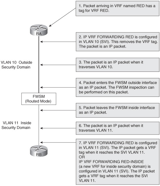
Figure 23-1 shows the logical flow of packets in a VRF through the FWSM with an example. Here the VRF in the outside security domain is depicted as RED. The Layer 3 VPN header information is removed at the Layer 3 next hop device connected to the FWSM. The packet enters the FWSM as an IP packet. After the packet leaves the FWSM in another security domain, the Layer 3 next hop device in the new security domain can add Layer 3 VPN definition to the packet. The packet can be placed in a new Layer 3 VPN or maintained in the old Layer 3 VPN.
Figure 23-1 Logical Flow of Packets for VRF Termination Concept on Layer 3 FWSM
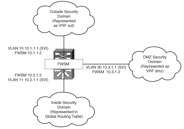
The outside interface in the switched virtual interface (SVI) is represented in VRF out (outside). The VRF out has its own virtual routing table.
The demilitarized zone (DMZ) is represented in the VRF dmz. The inside security domain is represented in the global routing table. The scenario in Figure 23-2 shows multiple VRF terminations at different security zones. The traffic from these VRFs flows to the global routing domain through the FWSM.
Figure 23-2 VRF Termination on FWSM
Because the FWSMs do not inspect labeled traffic, the key to pass the traffic through the security zones is to remove the Layer 3 VPN VRF tag from the packet before it reaches the FWSM. The IP packet traverses through the FWSM.
In this design, a single PFC is used for configuring a Layer 3 device for all security domains. The single PFC represents the Layer 3 next hop device at the outside and inside security domains. This is achieved by segregating the routing plane using VRF segregation.
In practical scenarios, multi-VRF using 802.1q or multiprotocol label switching (MPLS) can be used to extend these virtual domains across multiple Layer 3 hops.
Configuring the PFC
Follow the steps to configure Layer 3 segregation with multiple security domains on a single PFC. This configuration represents the PFC in Figure 23-2:
Configuring the FWSM
The FWSM is configured as a single context routed mode. Some of the key elements to be noted in this configuration are the following:
• VLANs for the respective security domains
• Static translation
• NAT translation
• Access list
• Applying the access list to the interface
• Route statements
The following configuration represents the FWSM in Figure 23-2.
Example 23-1 FWSM-A Configuration
Failover Configuration in Mixed Mode
Figure 23-3 illustrates the firewall configuration for multiple context modes. One of the contexts is in routed mode and the other is in transparent mode. VLANs defined in the FWSM are allowed on the trunk interface between the primary and secondary switches. The concept of Layer 3 VPN termination covered in the previous section is used to terminate security zones on the Layer 3 device.
Instead of using shared interfaces, the global routing table is leaked into the VRF outside. Each security context has its own VLAN in the VRF outside, instead of shared outside Layer 3 VLAN for both the contexts. The Department 1(DEPT1) and Department 2(DEPT2) security domains are represented as separate VRFs. If DEPT1 needs to access devices in DEPT2, the traffic first passes through the DEPT1 context; then it passes through the outside VRF and to DEPT2 context. In the same way, the traffic will traverse in the reverse direction. This removes the concept of a shared Layer 2 VLAN between contexts. In Figure 23-3, the context A and context A1 (standby) are in routed mode, and context B and context B1 (standby) are in transparent mode.
Figure 23-3 Hybrid Firewall/Failover Configuration

Table 23-1 shows the primary block switch and the secondary block switch configurations.
Table 23-1 Primary/Secondary Block Switch Configurations

Example 23-2 shows the primary FWSM system context configuration.
Example 23-2 Primary FWSM System Context Configuration
Example 23-3 shows the context A configuration (primary).
Example 23-3 Context A Configuration (Primary)
Example 23-4 shows the context B configuration (primary).
Example 23-4 Context B Configuration (Primary)
Refer to Chapter 12, “Failover in FWSM,” for configuring a standby FWSM unit.
Interdomain Communication of Different Security Zones Through a Single FWSM
Interdomain communication between various security zones has become very common, especially when firewalls are integrated in the data center environment.
Figure 23-4 illustrates a scenario in an enterprise network. The FWSM is configured for multiple context routed mode and VRF termination at the Layer 3 next hop to achieve zoning and routing segregations using the same device. In this scenario, consolidation is done when there is a requirement of a common security domain with multiple security domains, with restricted access.
Figure 23-4 Communication of Different Security Zones in a Single FWSM with Multiple Context Mode
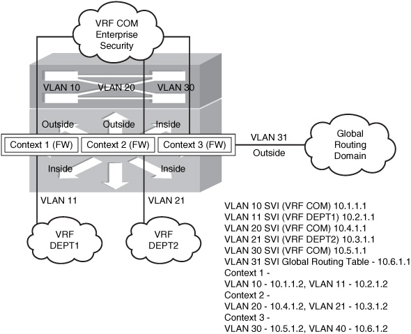
In Figure 23-4, the common security domain is represented in the VRF COM. The Department 1(DEPT1) and Department 2(DEPT2) security domains are represented as separate VRFs.
For the packet from DEPT1 to access DEPT2, it traverses through DEPT1 context, then to VRF COM, next to DEPT2 context, and finally reaches DEPT2’s routing domain. This scenario assumes that the security policy allows the IP packet flow between the contexts. Figure 23-4 gives a hierarchy of security domains in a single FWSM and a Layer 3 device representing each security domain.
Configuring the PFC
PFC is configured as the Layer 3 next hop device from the FWSM on each security domain. This is achieved by segregating the routing tables using Layer 3 VPN technology. This configuration represents the PFC in Figure 23-4. Follow the steps to configure segregation of routing for each security domain:
FWSM Configuration
The configuration in Example 23-5 represents the FWSM in multiple context mode. Refer to Figure 23-4.
Example 23-5 Configuration of the System Context
Example 23-6 shows the configuration of the FWSM in contextA.
Example 23-6 FWSM ContextA
Example 23-7 shows the configuration of the FWSM in contextB.
Example 23-7FWSM ContextB
Example 23-8 shows the configuration of the FWSM in contextC.
Example 23-8FWSM ContextC
Dynamic Learning of Routes with FWSM
Placement of the FWSM is very important in the design. The routing information from one security domain to the other can determine the resiliency of the design. Following are some of the methods that can be used to learn the routes between security domains:
• Method 1—Static routes: The traditional method is to use static routes. The Layer 3 device at the inside security domain has a default route that points to the inside interface of the FWSM. (In case of a failover scenario, the static route will point to the IP address of the inside interface in the primary FWSM.) The firewall will have static routes for the inside subnets pointing to the inside VLAN’s Hot Standby Router Protocol (HSRP) IP address. The FWSM will have a default route pointing to the outside VLAN’s HSRP IP address. At the PFC, the outside security domain will have subnets defined in the inside security domain, pointing to the outside IP address defined in the primary FWSM (in case of redundancy). The route statements will be present in the inside security domain for the IP addresses in the outside security domain pointing to the primary FWSM’s inside interface.
The dynamic failover of routing traffic to the FWSM is achieved with static routes because the next hop IP addresses in the static routes point to the virtual IP address. The FWSM points to the virtual IP address of the primary HSRP of the VLAN, and the Layer 3 device has a static route that points to the primary FWSM’s interface IP address for the respective domains. You should note that when using static routes, there is always a drawback of manual configuration in the network and firewalls for any changes in the network reachability. This is both time consuming and exhausting.
• Method 2—Enabling a routing protocol on the FWSM: Enabling a routing protocol on the FWSM is another way of routing packets. The FWSM can pass information about the routing next-hop IP address from one security domain to the other. The FWSM can be enabled with a routing protocol, such as OSPF, RIP, or BGP stub. For more information on implementing this solution, refer to Chapter 9, “Configuring Routing Protocols.”
• Method 3—Using BGP to carry routes between the domains: In this method, static routes are configured for next hop reachability between the security domains. The static routes in the FWSM get the BGP session established between the Layer 3 devices in the security domains, and the packet forwarding in the Layer 3 domain will be based on BGP routing updates. BGP will rely on static routes for its session to be established. The FWSM will have routes defined only for IP addresses that will establish the BGP session between the Layer 3 devices in the security domains and for subnets of the network present in each security domain. The Layer 3 next hop device connected to the FWSM will also have static routes, for the BGP session to be established. BGP is configured in the Layer 3 devices of different security domains.
The FWSM should have TCP port 179 open in the security rule set. The BGP connection is established and carries the routing information from one domain to the other. FWSM does not participate in BGP routing.
• Method 4—Routing updates through transparent firewalls: The FWSM in this design is in Layer 2 mode. OSPF, BGP, and EIGRP are common routing protocols that are used to exchange routes between different security zones. FWSM in transparent mode can have two interfaces. The route exchange in this case will be between the two interfaces in the same bridge group. Intermediate System-to-Intermediate System (ISIS) cannot be used to exchange routing information between two security domains in the transparent mode. The FWSM configuration will require the access-list command to permit the routing protocol ports. This methodology of route exchange is transparent to the FWSM.
Single Box Solution with OSPF
In Figure 23-5, the configurations for the Layer 3 device at the outside security domain, FWSM, and the Layer 3 device for the inside security domain are configured in a single chassis with the FWSM module. The concept of virtualization with Layer 3 VPNs is integrated as a solution with the FWSM. The following example with configuration will help you understand Method 4.
Figure 23-5 Method 4 for Route Learning Across Security Domains with OSPF
Example 23-9 shows PFC configuration of the Layer 3 next hop for the inside and outside security domains.
Example 23-9 PFC Configuration
Data Center Environment with the FWSM
The concepts covered in the previous sections change the perspective of the design principles for designing a data center. This brings the concept of virtualization through Layer 3 VPNs and the FWSM used together as a design solution.
In an enterprise customer environment, the current trend is consolidation of network infrastructure primarily to have reductions in the total cost of operation. Consolidation of the wide-area network (WAN) infrastructure is accomplished using Layer 3 VPNs.
This section goes through design details to consolidate the data center environment without using Spanning Tree. Here, multiple departments (for the same customer) can use the same switch/router/firewall in the data center environment and maintain separate security domains with traffic segregation.
There are two ways to achieve the desired design solution:
• Layer 3 VPN segregation (multi-vrf or MPLS) with Layer 3 FWSM in a multiple context mode.
• Layer 3 VPN segregation (multi-vrf or MPLS) with Layer 2 FWSM in a multiple context mode.
Method 1: Layer 3 VPN Segregation with Layer 3 FWSM (Multiple Context Mode)
The design has three logical blocks:
• Penultimate Hop Router
• Perimeter Device
• Distribution Block Device
These logical blocks are explained as follows:
• Penultimate Hop Router: This router removes the MPLS labels, in case MPLS Layer 3 VPNs are used for traffic segregation.
This router maps VRF based on VLANs and communicates with the perimeter router. The traffic of each VRF will flow through the VLANs in the individual trunk. Mapping the untagged traffic to each VLAN will be sufficient to achieve the segregation between the penultimate hop router and perimeter device. The technology of vrf lite (multi-vrf) is used in the penultimate hop router to achieve route segregation.
• Perimeter Device: For the interface connected to each FWSM virtual context (routed mode), a new SVI interface in the respective VRFs is defined on the PFC. This makes all links point-to-point and binds the SVIs defined within a VRF as a segregated zone.
The firewall can also have more than two interfaces defined. The outside, DMZ, and the inside interfaces will be present in a separate VRF instance. You can consider a scenario where a department has a firewall in its infrastructure, separating two security domains before it is migrated into the shared infrastructure. In such a case, these security zones can be defined as a separate interface in the firewall virtual context (in routed mode), and the respective VRFs can be defined on the switch SVI.
The routing instance for these departments will be separate for the individual security zones because they will be associated with each VRF. If the traffic is inter-VRF, the packet will have to pass through the firewall before it reaches the routing instance of the next VRF. The routing protocol used in this example is OSPF.
The next step is to maintain the segregation when the packet passes from the perimeter device to the distribution block device. This can be done in one of the two methodologies:
— If the infrastructure is Layer 3 and multiple hops exist between the last Layer 3 device and perimeter device, multiprotocol BGP with LDP is used to carry the Layer 3 VPN to the downstream routers.
— In a single hop scenario, the VRF-lite (multi-vrf) can be used for each segregate domain. Figure 23-6 has a VRF-lite because most of the campus environments have single hop Layer 3 devices instead of multiple Layer 3 devices. Note that VRF lite can also be used across multiple Layer 3 hops mapped to the respective VLANs.
• Distribution Block: The distribution block is a Layer 3 device and is the last hop in the data center before the traffic hits the Layer 2 access layer. Each distribution block will have its own instance of Spanning Tree. Here the Spanning Tree instances will be based on the distribution block in the data center campus.
These two logical blocks are defined based on functionality:
• Segregation of traffic
• Firewall alignment based on traffic segregation
You can use a separate device representing each block or can combine these functional blocks based on requirements.
Figure 23-6 Logical Explanation of Firewall Virtualization in a Data Center
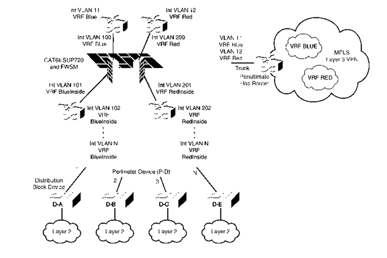
Method 2: Layer 3 VPN Segregation with Layer 2 FWSM (Multiple Context Mode)
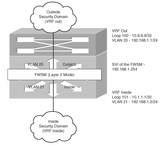
In Figure 23-7, the router RB/RA represents a MPLS domain for the enterprise WAN campus, and the RC represents another MPLS domain for the inside security domain. This design aims to achieve this dynamic communication using the FWSM in transparent mode. RA and RB are in the MPLS domain (LDP neighbors). OSPF is used in RA, RB, and PFC for next hop reachability. The VRF custB and custA are transported through multiprotocol BGP (VPNv4) from RA to PFC. At the PFC, each VRF is terminated and is mapped to VLANs that are represented in the FWSM context. The FWSM context is in transparent mode.
Figure 23-7Virtualization with FWSM in Layer 2 Mode
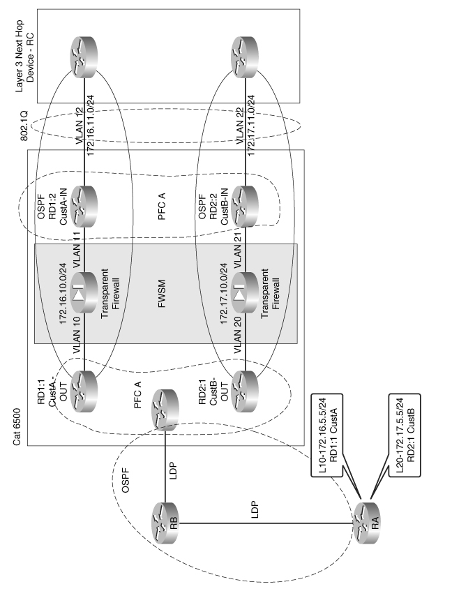
Multiple context transparent mode in the FWSM helps in dynamic route learning between the Layer 3 devices in each domain. Each context represents each VRF in the MPLS domain. From the outside VRF of the MPLS domain, a default route is advertised to the inside interface.
The inside interface of the FWSM is connected to a separate VLAN with the same subnet as the outside SVI. This inside VLAN is represented as VLAN 12 and this VLAN is mapped to a separate VRF. The VRF mapped to the inside VLAN is different from the outside VRF. This VRF for the inside interface is called the CustA-IN VRF for the respective customer. The outside security domain is represented as CustA-OUT VRF. An OSPF relationship will exist between the CustA-OUT VRF and the CustA-IN VRF because they are in the same subnet but different VLANs. This allows the route information to be dynamically learned across the two VRFs in separate MPLS domains across FWSMs. This example does not include the scope of using two FWSM modules across two chassis, which will help build redundancy to the design. This design gives the flexibility of having two MPLS domains to communicate across the firewall, with dynamic learning of the routes.
PVLAN and FWSM
What is PVLAN?
Private VLAN is a VLAN that is used to achieve Layer 2 isolation for hosts in the same subnet. A single VLAN can be split into multiple Layer 2 domains. Port configuration defines the domain segregation in a PVLAN. There are three types of PVLANs ports:
• Isolated: This has complete Layer 2 separation from other ports within the same PVLAN except for the promiscuous port. PVLANs block all traffic to isolated ports except traffic from promiscuous ports.
• Community: The hosts communicate among themselves and with their promiscuous ports. These interfaces are isolated at the Layer 2 domain from all other interfaces in other communities or isolated ports within their PVLAN.
• Promiscuous: Promiscuous ports can communicate with all interfaces, including the community and isolated ports within a PVLAN.
PVLAN Configuration in FWSM
The PVLAN concept was introduced in FWSM from 3.x code version onward. It is important for the switch code to be above 12.2.18SXFx version to integrate the PVLAN concept with the FWSM. Here x defines the version number. The primary VLAN of the PVLAN should be configured in the FWSM. No other special VLAN configuration is needed for PVLANs at the FWSM. Using PVLANs achieves Layer 2 segregation. This can be used in smaller DMZ designs where the servers in the DMZ within a single subnet need isolation. This helps to avoid major attacks in the DMZ security domain. Other virtualization techniques, such as Layer 3 VPN with MPLS labels or multi VRF, can also be used for Layer 3 segregation. These two techniques need a Layer 3 device.
In routed mode, the FWSM can act as a gateway between hosts on the PVLAN and the outside world. It secures the entire PVLAN itself from attacks initiated from the outside, and it stops malicious traffic originating from hosts on the internal PVLAN.
The concept of PVLAN facilitates pseudo security zones in a transparent firewall. The term pseudo is mentioned because these zones will not communicate with each other, but only with the inside interface. The inside interface is in promiscuous mode. The VLANs defined in a PVLAN represents the pseudo security zone.
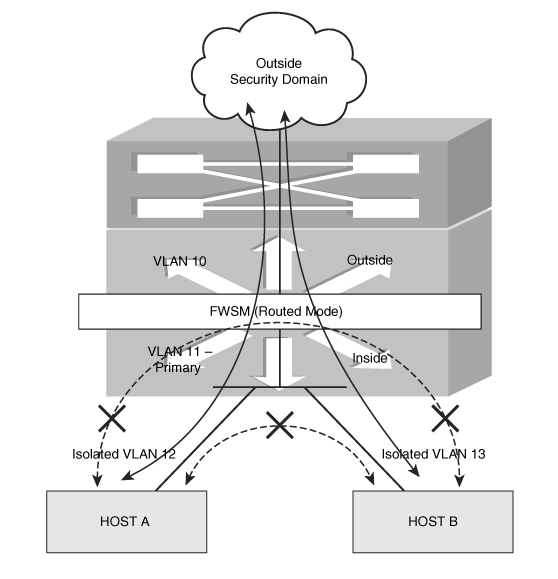
Design Scenario 1 for PVLAN in FWSM
In this scenario, as shown in Figure 23-8, the FWSM is in single context routed mode. The inside interface of the FWSM is in VLAN 11. VLAN 11 is primary for the PVLAN (promiscuous mode). VLAN 12 and VLAN 13 are isolated VLANs. The hosts in VLAN 12 and VLAN 13 do not communicate with each other. This results in isolation of the traffic between the two hosts. VLAN 12 and VLAN 13 communicate with the host in VLAN 10 or the outside security domain through VLAN 11. The FWSM will need to have VLAN 11 defined only in its inside interface. By default, traffic from one interface cannot be routed through the same interface. The FWSM will also not allow the traffic to pass from the host in VLAN 12 to the host in VLAN 13.
Design Scenario 2 for PVLAN in FWSM
In this scenario, as shown in Figure 23-9, the FWSM is in single context routed mode. VLAN 11 is the primary VLAN. VLAN 12 is an isolated VLAN and communicates only with the primary VLAN 11. VLAN 13 is defined as a PVLAN community and has two hosts. These two hosts, HOST B and HOST C, can communicate with each other through the switch.
Figure 23-9Using PVLAN Isolation with Host Communities

The following points represent the communication in Figure 23-9:
• HOST A (isolated VLAN) will communicate only with VLAN 11 and the outside security domain (based on the firewall policy).
• HOST B and HOST C can communicate with each other and will have access to the outside security domain (based on the security rule set) through VLAN 11 (inside interface of the firewall).
• HOST A cannot communicate with HOST B.
• The firewall (FWSM is in default configuration) will not route the traffic from HOST A to HOST B or HOST C.
Configuring PVLAN
The FWSM should have a 3.x code version or the preceding code, and the switch should have 12.2.18 SXFx version or the preceding code. Figure 23-10 shows the configuration of FWSM with PVLANs.
Figure 23-10Configuration of FWSM with PVLANs

• VLAN 10 is the outside interface of the FWSM.
• VLAN 11 is the inside VLAN for the FWSM. It is also the primary VLAN (also referred as promiscuous VLAN) for the PVLAN in the PFC.
• VLAN 12 is a PVLAN—Isolated.
• VLAN 13 is a PVLAN—Community.
• VLAN 14 is a PVLAN—Community.
The sequence of configuring the PVLAN is important:
To verify the switch port configuration, enter the show interface g 1/1 switchport command:
6504-E-1# show interface g 1/1 switchport
Name: Gi1/1
Switchport: Enabled
Administrative Mode: private-vlan host
Operational Mode: private-vlan host
Administrative Trunking Encapsulation: dot1q
Operational Trunking Encapsulation: native
Negotiation of Trunking: Off
Access Mode VLAN: 1 (default)
Trunking Native Mode VLAN: 1 (default)
Voice VLAN: none
Administrative private-vlan host-association: 11 (VLAN0011) 12
(VLAN0012)
Administrative private-vlan mapping: none
Administrative private-vlan trunk native VLAN: none
Administrative private-vlan trunk encapsulation: dot1q
Administrative private-vlan trunk normal VLANs: none
Administrative private-vlan trunk private VLANs: none
Operational private-vlan: none
Trunking VLANs Enabled: ALL
Pruning VLANs Enabled: 2-1001
Capture Mode Disabled
Capture VLANs Allowed: ALL
Unknown unicast blocked: disabled
Unknown multicast blocked: disabled
— CLI for promiscuous VLAN port configuration:
switchport private-vlan mapping primary-VLAN Secondary-VLAN
switchport mode private-vlan promiscuous
For example:
6504-E-1# show run interface g1/2
Building configuration …
Current configuration : 218 bytes
interface GigabitEthernet1/2
switchport
switchport private-vlan mapping 11 13-14
switchport mode private-vlan promiscuous
no ip address
media-type rj45
end
To verify the switch port configuration, enter the show interface g 1/2 switchport command:
6504-E-1# show interface g 1/2 switchport
Name: Gi1/2
Switchport: Enabled
Administrative Mode: private-vlan promiscuous
Operational Mode: private-vlan promiscuous
Administrative Trunking Encapsulation: negotiate
Operational Trunking Encapsulation: native
Negotiation of Trunking: Off
Access Mode VLAN: 1 (default)
Trunking Native Mode VLAN: 1 (default)
Voice VLAN: none
Administrative private-vlan host-association: none
Administrative private-vlan mapping: 11 (VLAN0011) 13 (VLAN0013) 14
(VLAN0014)
Administrative private-vlan trunk native VLAN: none
Administrative private-vlan trunk encapsulation: dot1q
Administrative private-vlan trunk normal VLANs: none
Administrative private-vlan trunk private VLANs: none
Operational private-vlan: none
Trunking VLANs Enabled: ALL
Pruning VLANs Enabled: 2-1001
Capture Mode Disabled
Capture VLANs Allowed: ALL
Unknown unicast blocked: disabled
Unknown multicast blocked: disabled
Follow the steps to complete the PFC configuration:
Step 1 | Follow the sequential steps to configure the PVLAN. |
Step 2 | Configure VLAN 10. |
Step 3 | Configure static routes. |
Step 4 | Configure the firewall VLAN group and the multiple interfaces command. |
Example 23-11 shows FWSM configuration for Figure 23-10.
Example 23-11 FWSM Configuration
Use the following command to verify PVLAN association with the primary VLAN in the FWSM:
FWSM-A# show np 1 vlan 14 | in private Vlan
primary Vlan for private Vlan : 11
FWSM-A# show np 1 vlan 12 | in private Vlan
primary Vlan for private Vlan : 11
FWSM-A# show np 1 vlan 13 | in private Vlan
primary Vlan for private Vlan : 11
Even though there is no configuration in the FWSM with the code supporting PVLAN feature, when VLAN 11 (primary VLAN) is enabled in the FWSM, the NP 1 (Network Processor) of the FWSM picks up all the PVLANs from the PFC.
Summary
This chapter covers options that readers can use to design a secured firewall infrastructure aligned with network virtualization. The principles of high availability and resiliency are achieved with a combination of features in FWSM and networking. Designing is an art, and requirements give birth to innovation using a combination of features from various technologies.