
Visible Control Using the Facility Layout
Attaining flexibility in the number of workers at a workshop to adapt to demand changes is called Shojinka. … Shojinka … means to alter (decrease or increase) the number of workers at a shop when the production demand has changed (decreased or increased).
… Shojinka is equivalent to increasing productivity by the adjustment and rescheduling of human resources. … flexible workshop … is essentially a workshop which is achieving Shojinka …
—Monden (1993, p. 159)
Basic Types of Facility Layouts
The facility layout is the physical arrangement of the parts of the processes (departments, work centers, or equipment) within a facility. The facility layout provides the framework for the resource assignments and the structure for information and knowledge integration. There are three major types of layouts—the product layout, the process layout, and the cellular layout (a combination of the product and process layout).
- The product layout (e.g., a flow line) uses highly specialized machines and places the equipment and machines in the sequence in which the production of the product requires their use. The product layout is the organization of the actual production processes into the sequence in which they need to be performed to manufacture or assemble a particular product.
- The process (or functional ) layout uses general purpose machines and places the machines and equipment that do the same function together (e.g., lathes are all located together).
- The cell layout uses general purpose machines and places them in the sequence in which they are used in the production of the product. Cellular manufacturing is a layout of machines and equipment that is suitable for small lots of material with higher variety than the process layout, but lower volume for each than the product layout.
Selecting the Correct Facility Layout
The type of layout that is most appropriate for your shop depends on both the volume of the product being produced and the variety being produced. As the facility layout predetermines the assignment of resources, it should be aligned with the customer requirements in terms of, for example, cost efficiency and flexibility. As shown in Figure 4.1, the volume and variety typically determine the manager’s choice of which of the three basic layouts to use (Hayes and Wheelwright 1984). The product layout produces items of high volume and high standardization (i.e., low variety). As the volume decreases, companies compete more on the basis of variety, which requires different layouts of the process. At the highest variety level, the volume is low and the most appropriate layout is a process layout where all of the machines and equipment that perform one type of function (e.g., saws) are placed together. At a midrange variety when there is adequate volume of a family of products, a cellular layout performs well, where cells are dedicated to particular families of products.
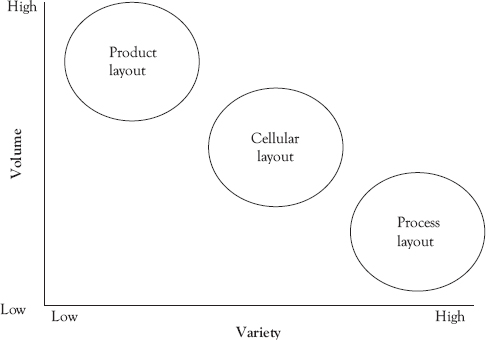
Figure 4.1 Product–process matrix!
For decades, America had cut costs while producing fewer types of cars. It was an American work style …. Our problem was how to cut costs while producing small numbers of many types of cars. (Ohno 1988, p. 1)
Importance of Facility Layout
The facility layout determines the flow of information, the flow of work, the assignment of resources, and the amount of motion that is required to perform the work at each step in the process. The layout decision also helps to determine how flexible the facility is in two ways:
- It determines how easy it is to add and or remove workers as demand increases or decreases, and
- It determines how easy it is for individuals in the process to work as a team to facilitate the flow of work through the process.
A flexible layout allows a firm to adapt as demand volumes changes. As stated earlier, the most flexible layout is the process or (functional) layout, which is illustrated in Figure 4.2. This type of layout groups all of the similar processes together. In the following example it groups all the circles together, and all of the squares together and keeps them separate from the triangles. If the circles were all saws and the squares were all lathes and the triangles all mills of various types, the parts would have to be transferred from each functional group to the next. So, the functional layout results in a high level of material movement, because the material has to be moved from department to department, where each machine function is located. Typically, this results in large batches being moved between departments. Moreover, the separation of each department from the other hides what is occurring within one department’s process from the other departments involved in producing the same product. Thus, it hinders communication between the different dependent operations that in turn hinders the coordination of the process. Less coordination means longer delays between steps, which reduces performance. As a result, the cost per unit produced in the process layout is more expensive compared to other layouts as the volume increases.
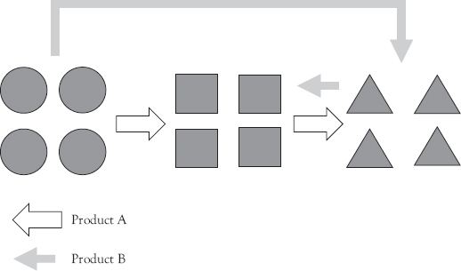
Figure 4.2 Process (or Functional) layout
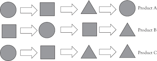
Figure 4.3 Product layout
The product layout resides on the other extreme of the product– process matrix dedicating resources to only one product or a product group. While this provides the highest efficiency, the flexibility of the layout to react to design changes is restricted. As illustrated in Figure 4.3, it aligns the different resources—presented by the circles, squares, and triangles—required to produce the product in order of the production sequence. To obtain higher efficiency, these resources might be highly specialized (i.e., designed to produce a very limited range of products), which makes them less flexible.
While the process (or functional) layout is the most flexible and the product layout the most cost efficient at high volume, companies typically have to be both efficient and flexible. This can be achieved for mid-range volumes by using a cellular layout (Hyer and Wemmerlöv 2002). The cellular layout places dissimilar processes next to each other. Figure 4.4 illustrates this with a circle, square, and triangle being placed in the same square. Each cell is dedicated to producing a family of related products, so it can switch from one product to another with little setup time. In addition, in the cellular layout the machines can be placed next to each other so that units can be produced one-by-one. An individual worker could even walk the units through production, by walking it from machine to machine and performing the required operations at each machine. Another advantage of this layout is that the volume of the cell is flexible and can be expanded, within limits, by putting more workers in the cell. In addition, the entire production process is visible to everyone who is working in the cell. Thus the communication is explicit and coordination between workers is facilitated by line-of-sight communication. The cellular layout prefers smaller more general purpose machines than the product layout, so that the cellular layout can be readjusted as demand changes.
The cell also makes any variance in the process visible, since there is only one input and one output point in the cell (Monden 1993). This makes variability in the process visible and distinguishes the cellular layout from the process layout. Making variability visible provides information and creates knowledge about the performance of the process. This knowledge allows buffers to be used very effectively (the right amount at the right time at the right place) and variance to be reduced from the outset. The process layout allows the greatest variety of products to be produced, but it hides variance in the process because there are many material movements, there are many material stocking points, and it is difficult to track where variance is affecting the process. The variance is hidden by the large amount of inventory in the system. Consequently, it is difficult to control the variance and the buffers may become quite large.
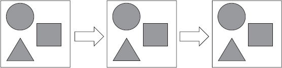
Figure 4.4 Cell layout
Issues in Cellular Layouts
Even within a cell, it is important to place the machines so that the cell layout will facilitate staffing by various numbers of workers as the demand fluctuates. This increases the volume flexibility of the cell. A good layout that increases volume flexibility is the U-shaped layout. The U-shaped layout, shown in Figure 4.5, has three workers (☺) performing three operations each. The workers move between the resources they are using in the sequence shown by the arrows. For example, one worker moves from point 1 to point 2 to point 3 and back to point 1. When this worker finishes steps 1 and 2 of their tasks, they hand the work piece off to the next worker who is following the sequence shown as 4, 5, 6, and back to 4. In this way, the work moves around the U shape, as it is handed off from worker to worker. As stated earlier, a piece of material starts on the upper left and is moved by the first worker from process step 1 to process step 2 and then it is handed to the second worker who works on it in #4. The second worker hands it to the third worker who then works on it for steps 7, 8, and 9, where it is in turn handed back to the second worker for steps 5 and 6 and then handed to the first worker who completes it in step 3.
One advantage of the U-shaped layout is that it has a clear entrance and exit. If demand drops, one worker can be removed and two workers can produce work by sharing the steps of the worker who is moved somewhere else in the facility. If demand increases another work can be added and the nine steps can be divided between four workers instead of three workers.
An advantage of this U-shaped layout over a bird cage or isolated layout (see Figure 4.6) is that the workers are not isolated from each other. The workers are able to help each other when one gets into trouble. This work within the same cell also helps to facilitate team structure and team accountability.
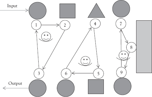
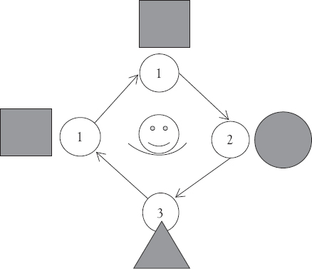
Figure 4.6 Bird cage or isolated layout
The isolated Island layout in Figure 4.6 does reduce worker walking and may increase individual worker efficiency, but in this isolated layout, the workers are not likely to communicate problems to each other and share and develop knowledge about the process; so they cannot help each other out and will tend to build inventory to protect themselves. These characteristics mean that the ability of the system to respond to change will be limited.
General Rules of Facility Layouts
Human beings and machines are completely separate from one another in the Toyota production system. Machine layout, therefore, follows the process flow of the product. The “flow of people,” however, is entirely independent of machines and need not adhere to the product flow; …
This means that comprehensive layouts, such as the V, L, or U-layout, are needed because they address themselves to the flow of both product and people. As much as possible, equipment should be laid out around the outside of the chosen pattern and workers stationed on the inside, both to reduce isolation and to facilitate mutual assistance. (Shingo 1989, p. 155)
Note that in the quote above, Shingo is providing some general principles for the layout that go beyond the three basic types of layouts discussed above. Two clearly stated principles are:
i. |
To eliminate unnecessary walking by the workers; and, |
ii. |
To eliminate isolation of the workers, which allows the workers to help each other. |
A lean work design seeks to minimize the amount of “movement” that is required within the process. Each worker’s capacity is restricted to their scheduled hours of work. Unnecessary movement by the workers means that process capacity is wasted and cannot be used for realizing work. Lean typically selects equipment and the layout so that the process is flexible and can easily be adjusted to changes in customer needs. So, a lean system can effectively produce a larger variety of products in a larger range of volumes. This allows lean companies to incorporate aspects of make-to-order production within mass production, which is typically make-to-stock. This is illustrated by the quote that follows:
As noted above, one piece flow production requires quantity leveling, small lots, and synchronization between processes. Since it greatly increases the number of transport operations, two strategies have been developed to reduce overall transportation time:
- Alteration of plant layout so that little or no transport is required
- Use of some other convenient method of linking processes, such as a conveyor belt
Since the latter method maybe troublesome and expensive, layout improvement is generally preferable. (Shingo 1989, p. 102)
Labor Flexibility and Facility Layout
One essential aspect of being able to use the more flexible facility layouts is that the workers themselves are flexible. This can be achieved in part by implementing job rotation for the workers. If the workers are only trained on one job, then they cannot perform the wide range of tasks that may be required in a flexible layout. For the flexibility of the layout to be realized in practice, the workers have to be able to do a task that another worker had been doing.
One method to increase the worker flexibility is to organize labor assignments so that the worker rotates through the different operations in a facility. This job rotation has to be managed to ensure that all of the workers have the required capabilities.
The rotation of workers through the various jobs is often managed using a job training sheet or a labor skills matrix. This sheet shows the workers and their ability to perform different tasks. It allows managers to plan the required training and to know what rotations can be realized during a shift. An example of a labor skills matrix is given in Table 4.1. This matrix makes it clear that worker A is fully trained in all four processes, while worker B has no training in processes 3 and 4 and worker C is only partially trained in any of the four processes. To be able to implement job rotation among these workers, workers B and C need to be fully trained.

Synchronization or line balancing is essential in any series of flow operations. It follows that every effort should be made to segment tasks and establish standard operations in order to minimize balance-related losses.
In practice, however, no matter how scrupulously operations are planned and executed, some deviations from standard times will occur. For example, a screw may be too tight and little more time than usual is required to loosen it …. These little troubles inevitably occur, so some degree of deviation from standard times cannot be avoided.
… typically, we deal with these problems by placing buffer stock between workers. When they complete their work ahead of schedule, workers process stocked products; when one worker is delayed, the next draws from his or her buffer stock and the delayed worker tries to recover lost time by working faster in the next cycle. Thus, the product stocked between workers serves as a buffer to absorb and prevent delays between processes. (Shingo 1989, p. 104)
The facility layout decisions influence the placement and size of the buffers and how variance is buffered within the system. The product layout only produces a very limited variety of products and seeks to achieve cost reduction through economies of scale. In this system, internal buffers of stock and time may occur only intermittently through the system. For example, there may be five or six cars in a queue between assembly departments. This queue can then buffer the departments from each other, but there may not be any buffering within the department.
Managers strive to eliminate variance from the system, which reduces the need for buffering within the system. Even with no variance internal to the system, the system may be buffered on the input side to prevent variance in material arrivals from disrupting the system. This can be done using limited raw material stocks. The system may also be buffered on the output side by using the finished goods inventory. Since most real systems have at least a minimal amount of variance internally, the system can be buffered internally by having steps or processes that have limited safety capacity followed by processes that have a large amount of safety capacity. When the processes are synchronized so that they are operating at the same rate, inventory will not build between them. But when one falls behind, it is possible for the processes with extra capacity to help the other process catch up.
As stated earlier, a variety of related products can be produced using a cellular layout. This allows a higher demand variance to be buffered by the flexible capacity of the cell as workers can move from one process to another to increase or decrease output to meet demand.
References
Hayes, R.H., and S.C. Wheelwright. 1984. Restoring Our Competitive Edge: Competing Through Manufacturing. New York: John Wiley & Sons.
Hyer, N., and U. Wemmerlöv. 2002. Reorganizing the Factory: Competing Through Cellular Manufacturing. 1st ed. Portland, OR: Productivity Press.
Monden, Y. 1993. Toyota Production System: An Integrated Approach to Just-in-Time. 2nd ed. Norcross, GA: Industrial Engineering and Management Press.
Ohno, T. 1988. Toyota Production System: Beyond Large-Scale Production. Published in Japanese by Diamond, Inc., Tokyo, Japan, 1978. Translation into English by Productivity Press, Boca Raton, FL: Taylor & Francis Group, LLC, CRC Press.
Shingo, S. 1989. A Study of the Toyota Production System from an Industrial Engineering Viewpoint. Cambridge, MA: Productivity Press.