Sony calls the official manual for the a6600 a “Help Guide,” which many take to mean that the average user needs a lot of help to use it. It’s 629 pages long and includes page upon page of tiny black-and-white drawings impaled with dozens of callouts. Six pages are devoted just to labeling the 250-plus individual icons that can appear in the viewfinder and LCD screen. Seeking information about a specific feature is a lot like being presented with a world globe when what you really want is to locate the capital of Brazil.
I’ll take a somewhat different approach in this book, particularly in this “roadmap” chapter. Rather than provide you with a satellite view, I’ll give you a street-level map that includes close-up, full-color photos of the camera from several angles, with a smaller number of labels clearly pointing to each individual feature. And, I don’t force you to flip back and forth among dozens of pages to find out what a component does. Each photo is accompanied by a brief description that summarizes the control’s functions, so you can begin using it right away. Only when a feature deserves a lengthy explanation do I direct you to a more detailed write-up later in the book.
Using Cross References
“I wish I could learn everything I need to know about a feature in one place!”
Some readers find cross references inconvenient. They’d like to open the book to one page and read everything there is to know about using, for example, the bracketing feature. Unfortunately, it’s not possible to explain everything there is to know about every button and control (or indeed, any feature of the a6600) with anything less than a mammoth 100-page chapter.
But it is possible to tell you what you absolutely must know to get started. So, if you’re wondering what the right directional button on the control wheel does (it summons the ISO adjustment screen), I’ll tell you up front, rather than have you flip to several pages. This book is not a scavenger hunt. But after I explain how to use the drive mode dial to select continuous shooting, I will provide a cross-reference to a longer explanation later in the book that clarifies the use of the various drive modes, the self-timer, and exposure bracketing. Unfortunately, it’s impossible to understand some features without having a background in what related features do. Explanations of how to bracket exposures aren’t useful for those who need to first understand all the available exposure options.
So, my strategy is to provide you with introductions in the earlier chapters, covering simple features completely, and relegating some of the in-depth explanations to later chapters. For veteran enthusiasts, the introductions may be all they need; less-experienced photographers will be glad I didn’t make unwarranted assumptions about what they already know. Feedback from readers have told me that this kind of organization works best for the broadest possible audience working with a camera as sophisticated as the Sony a6600. (Remember, you were a beginner once, too, and you can always skip any sections if you feel you won’t benefit from a refresher.)
In all cases, however, by the time you finish this chapter, you’ll have a good understanding of every control and of the various roles each can take on. I’ll provide a lot more information about items in the menus and submenus in Chapters 3, 4, 5, and 6, but the following descriptions should certainly satisfy the button pusher and dial twirler in you.
Front View
When thinking about any given camera, we always imagine the front view. That’s the view that your subjects see as you snap away, and the aspect that’s shown in product publicity and on the box. The frontal angle is, essentially, the “face” of a camera like the Sony a6600. But, not surprisingly, most of the “business” of operating the camera happens behind it, where the photographer resides. The front of the camera has very few controls and features to worry about. These few controls are most obvious in Figure 2.1:
- AF illuminator/Self-timer lamp. This bright LED flashes while your camera counts down the 2-, 5-, or 10-second self-timer. In 5- and 10-second modes, the lamp blinks at a measured pace off and on at first, then switches to a faster blink cycle in the final moments of the countdown. When the self-timer is set to 2 seconds, the lamp stays lit throughout the countdown. Stop the self-timer, once initiated, by pressing the shutter release a second time. This lamp also serves as the AF (autofocus) Illuminator, emitting its orange-red glow in dark conditions to help the camera’s autofocus system achieve sharp focus. You can enable/disable the AF illuminator in the Camera Settings I-06 (AF2) menu. (You’ll learn how to navigate menus in Chapter 3.)
- Remote sensor. Detects infrared signals from the RMT-DSLR1 or RMT-DSLR2 Wireless Remote Commanders to take still pictures and (with the RMT-DSLR2 model only) to start/stop movie recording. Make sure the IR Remote Control entry in the Setup 3 menu is set to On. (That setting has no effect on the RMT-P1BT wireless remote commander, which is activated using the Network 2 menu, described in Chapter 5.) I’ll show you how to adjust the various IR remote control options in Chapter 6.
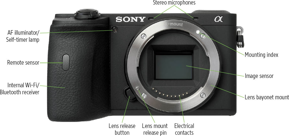
Figure 2.1
- Lens release button. Press and hold this button to unlock the lens so you can rotate it to remove the lens from the camera.
- Lens mount release pin. Retracts when the release button is pressed, to allow removing the lens.
- Mounting index. Match this recessed, white index button with a similar white indicator on the camera lens’s mount to line the two up for attaching the lens to the a6600.
- Lens bayonet mount. Grips the matching mount on the rear of the lens to secure the lens to the camera body. While some early E-mount cameras had relatively weak lens mounts, later models and the a6600 have a sturdy mount fully capable of supporting many longer lenses. However, it’s always a good idea to hold one hand under a very long lens and, if using a tripod or monopod, attach the support to the tripod socket of the lens (if available), rather than the one on the bottom of the a6600 body.
- Electrical contacts. These metal contact points match up with a similar set of points on the lens, allowing for communication with the camera about matters such as focus and aperture.
- Image sensor. This fairly ordinary-looking little rectangle is the heart and soul of your digital camera. On the a6600, this EXMOR sensor is a CMOS (complementary metal-oxide semiconductor) device, approximately 23.5 × 15.6 mm in size, with 24 megapixels of resolution.
- Internal Wi-Fi/Bluetooth receiver. You can’t access the Wi-Fi/Bluetooth antenna built into the hand grip of the a6600, but it’s good to know where it is, so you don’t accidentally wrap it in tin foil or something.
- Stereo microphones. This pair of front-facing microphones capture stereo sound from your subject (and may also pick up noise from camera operations, such as autofocus, which is why plugging in an external mic is a good option).
In Figure 2.2 you can see the terminals/ports hidden under the cover that provides a modicum of protection from dust and moisture for the four internal connectors.
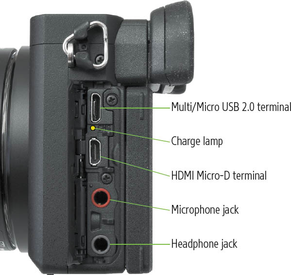
Figure 2.2
- Multi/Micro USB 2.0 terminal. This connector can be used to upload images to the computer; to charge the battery while it’s in the camera; and to upgrade the firmware to the latest version available for the a6600, using a file downloaded from the Sony support website (www.esupport.sony.com). The same port serves as a charging port when the USB cable is connected to a powered USB port on your computer or an AC charging adaptor or power pack, as I explained in Chapter 1.
- Charge lamp. This yellow LED flashes while battery charging is underway, and the camera is powered by an external source.
- HDMI Micro-D terminal. If you’d like to see the images from your camera on a television screen, you’ll need to buy an HDMI cable (not included with the camera) to connect this port to an HDTV set or monitor. You can also link to an external video recorder when using DUAL REC mode to output 4K video to both the memory card and recorder. Be sure to get a Type-D cable; it has a male micro-HDMI connector at the camera end and a standard male HDMI connector at the TV end.
Once the cable is connected, you can not only view your stored images on the TV in Playback mode, you can also see what the camera sees by viewing your TV screen. So, in effect, you can use your HDTV set as a large monitor to help with composition, focusing, and the like.
- Microphone jack. Allows connecting an external stereo microphone to provide better audio recording than the a6600’s built-in mics.
- Headphone jack. You can monitor audio as you shoot video and listen to your movies during playback by plugging an external headphone into this jack.
The Sony a6600’s Business End
The back panel of the a6600 is where many of the camera’s physical controls reside. There are roughly a dozen and a half of them, and, as I noted earlier, some can perform several functions, depending on the context.
Most of the controls on the back panel of the a6600 are clustered on the right side of the body, with several located on the top edge. The key components labeled in Figure 2.3 include:
- MENU button. Press to enter the multi-tabbed menu system. This button also serves to exit many functions, including menu settings, and playback zoom. A Menu/Exit label will appear in the viewfinder or LCD in that case.
- Viewfinder. Look into this window to activate the eye-level electronic viewfinder (EVF), an internal OLED (organic LED) display with 2.36 million dots of resolution. The a6600 supports a customizable frame rate for this EVF, with options of either 60 fps or 120 fps.
The viewfinder shows 100 percent of the frame at 1.07X magnification (with a 50mm focal length focused at infinity), making it virtually the equal of optical viewfinders found in traditional digital SLR cameras. I actually like it much better in many circumstances, such as when shooting in dim light, when the view is quite bright. It’s not as useful for continuous shooting as the camera may not show the previous image rather than a “live” view at the highest shooting speeds. You can frame your composition and see the information on the electronic viewfinder’s display.
While some shooters will use the rear-panel LCD monitor for framing their photos instead of the electronic viewfinder, the latter offers some benefits. On sunny days, when the LCD display is often obliterated by glare, the EVF is preferable. You might also want to use it for reviewing your images and video clips in Playback mode. Holding the camera pressed up against your face helps provide extra steadiness to reduce camera shake (and image blurring) at very slow shutter speeds. (Even the in-body 5-axis SteadyShot stabilization, or the optical SteadyShot included in some lenses, is not a panacea and is more effective when the camera is at least somewhat stable.) Both EVF and LCD monitors can be used with the camera’s focus peaking and focus magnification features, which makes it easier to achieve sharp focus manually.
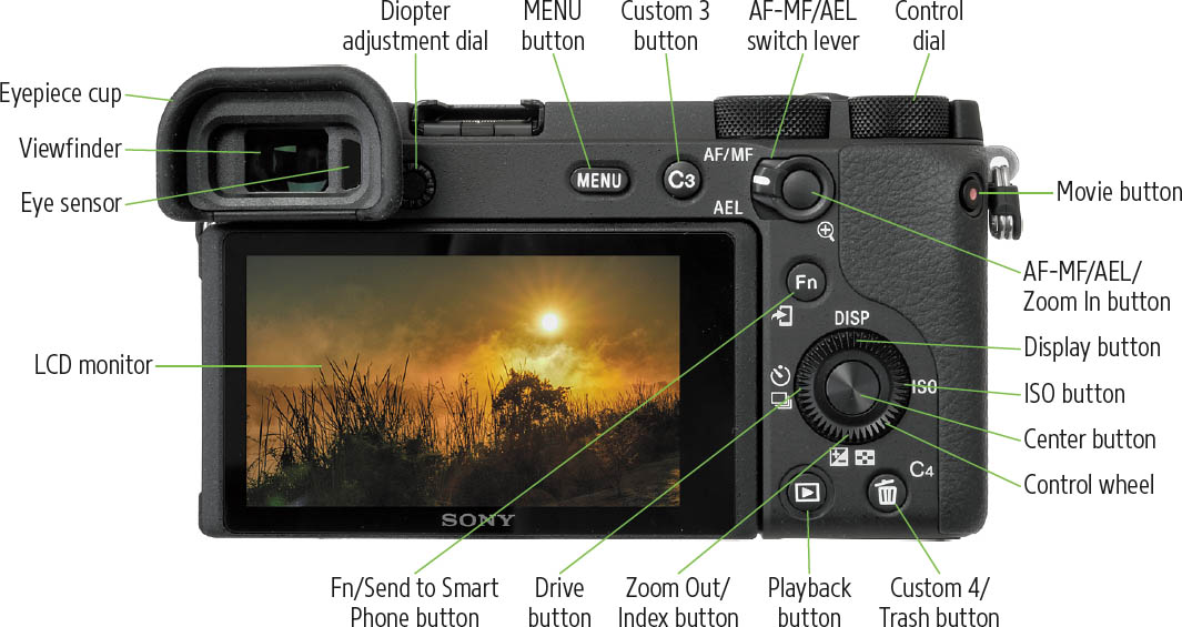
Figure 2.3
- Movie button. This button with a central red dot is located at the upper-right corner of the back of the camera, where it’s easy to access but placed out of the way to avoid pressing it accidentally. This design was intended to minimize the risk of inadvertently starting to record a video clip. When you want to make a movie, there is no need to change the Shooting mode, or to fiddle with menu systems, as with some other cameras. Simply press the record button; when you’re finished, press it again to stop recording. I’ll discuss your movie-making options in Chapters 10 and 11.
- Control dial. Adjusts various settings. It’s often used in conjunction with the control wheel to adjust pairs of settings, such as shutter speed and aperture.
- Eye sensor. This solid-state device senses when you (or anything else, unfortunately) approach the viewfinder; the camera then triggers a switch that turns off the back-panel LCD, activates the viewfinder screen, and starts the autofocus system. You can enable or disable either of these features, as I’ll explain in Chapter 4.
- Eyepiece cup. This soft rubber frame seals out extraneous light when pressing your eye tightly up to the viewfinder, and it also protects your eyeglass lenses (if worn) from scratching.
- Diopter adjustment dial. As described in Chapter 1, you can spin this to adjust the built-in diopter correction to suit your vision. Since it’s right beside the viewfinder window, it’s a bit difficult to change the diopter setting while your eye is at the EVF, but it’s worth taking the time to adjust it.
- AF-MF/AEL switch lever. Rotate this switch to change the function of the button located in the center of the switch.
- AF-MF/AEL/Zoom In button. Note that, as I’ll explain in Chapter 4, you can redefine the functions of the button (as well as other buttons and controls) using several different entries in the Custom Settings II-08 menu.
- AF/MF position. With the switch in this position, pressing and holding the button changes the focus method to the opposite method temporarily. If the camera is set for autofocus, holding the button switches to manual focus; if the camera is set for manual focus, holding the button down switches to autofocus and locks the focus. In Chapter 4, I’ll show you how to adjust the behavior of this button so it simply toggles between AF and MF, without the need to hold the button down.
- AEL position. Rotating the switch to the AEL position and pressing and holding the button locks exposure by default. An asterisk appears in the lower-right corner of the LCD or viewfinder to show you exposure has been locked. If you keep it depressed, you can then recompose and the exposure will not change; it will remain optimized for your primary subject. The Custom Key (Shooting) entry in the Camera Settings II-08 menu has an AEL Button option that allows you to turn the button into a toggle switch, so you will not need to hold it down to maintain autoexposure lock.
Since the AEL button is customizable, that menu item also allows you to change its purpose entirely, so it activates shooting tips or one of many other camera functions instead of providing autoexposure lock. If you use a certain function very often, you might want to program the AEL button to activate the screen to set the desired option of that camera feature. (I won’t list all of the options of the menu item here, but will do so in Chapter 4.) Of course, you will need to remember the purpose you have assigned to the AEL button, but that won’t be difficult unless you change its behavior often in the menu.
![]()
TIP Many buttons on the a6600 can be redefined to some other action, allowing you to tailor the camera’s operation so it best suits your needs, as I’ll describe in Chapter 4. However, keep in mind that customizing your camera’s behavior can be confusing—both for you and for others you may allow to use the camera.
- In Playback mode (zoom). When you’re reviewing images, the position of the switch doesn’t matter; when you press the AF/MF/AEL button, the camera will always activate the zoom feature of the image display. While reviewing pictures, pressing the Playback button activates the zoom-in feature. You can press the button multiple times to progressively zoom in on your image, or rotate the control wheel (on the back of the camera) clockwise to zoom in. Zoom out by rotating the control wheel counterclockwise. To exit zooming, press the MENU button.
- Fn/Send to Smart Phone button. In Shooting mode, press the Fn button to produce a screen with shooting setting options, as seen in Figure 2.4. By default, the 12 functions shown are displayed. However, as I’ll describe in Chapter 4, you can choose exactly which functions you’d like to display, and you aren’t locked into 12. If you prefer, you can define a single row of six favorite functions, or include some other number/combination of choices.
- 1. Access Fn menu. Press the Fn button and use the directional keys to highlight one of the options.
- 2. Make adjustment. When your setting is highlighted, you can rotate the control wheel or use the left/right directional buttons to cycle through the available choices, which will appear one by one as you spin. Optionally, when the function is highlighted, you can press the center button to produce an adjustment screen with all the choices shown. Use the up/down directional buttons, the control dial, or control wheel to select the one you want. Note that with either method, some choices are accompanied by a right-pointing arrow that indicates there are additional sub-options (such as Level 1, 2, or 3 with the Dynamic Range Optimizer). Press the right button to access these extra options.
- 3. Confirm. Press the center button to confirm your choice and return to the Function menu.
- Custom 3 button. This button’s dual features are not complicated. When shooting images, the C3 button changes Focus Area. In Playback mode, the button’s function does not change, but you can assign a behavior using the Custom Key (Playback) entry in the Camera Settings II-08 menu. I like to define this button to protect/unprotect an image when pressed, so it can/cannot be accidentally deleted. (Using the Format command overrides protection, however.)
- Custom 4/Trash button. This button has no default function in shooting mode. I like to define it to enable/disable the touch screen using the Custom Keys feature. In Playback mode, the button serves as a delete key.
- Playback button. Displays the last picture taken. Thereafter, you can move back and forth among the available images by pressing the left/right directional buttons or spinning the control wheel (on the back of the camera) or control dial to advance or reverse one image at a time. To quit playback, press this button again. The a6600 also exits Playback mode automatically when you press the shutter release button halfway (so you’ll never be prevented from taking a picture on the spur of the moment because you happened to be viewing an image).
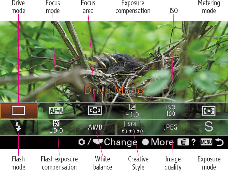
Figure 2.4 Up to 12 user-selectable choices are available in the Function menu. This is the default layout.
- Control wheel. This ridged dial, which surrounds the large center button, also has multiple functions, depending on the camera’s mode. In both Shooting and Playback modes it can be useful for navigating menu screens to get to the item or option you want to use.
The control wheel performs several important functions and is the only control on the camera that can be activated in two different ways: you can turn the ridged part of the wheel to perform certain actions (such as navigation or setting exposure controls), and you can press in on the various edges at top, bottom, left, and right. In that mode the edges serve as directional buttons that are incorporated into the north, east, south, and west positions of the wheel while navigating through menu screens, for example.
When the camera is in Shooting mode, rotating the control wheel changes shutter speed in Manual and Shutter Priority modes, and changes the aperture in Aperture Priority mode. If you’re using Program mode, the control wheel produces different combinations of shutter speed and aperture that produce the same exposure (program shift). The four directional buttons are used to make adjustments. For example, when the Autofocus Area is set to Flexible Spot, you can use all four of the directional buttons to move the focus bracket to any of its available positions on the screen.
- Control wheel buttons (Shooting mode). The center button, left, right, up, and down directional buttons function in two different ways when in shooting mode.
- Direct access functions. Each directional button can serve as a direct access key to summon Display (Up button), Drive Mode (left button), ISO (right button) or Exposure Compensation (down button) adjustments.
- Focus Standard. Those same buttons can serve as left/right/up/down directional buttons for moving the focus point/zone around within the frame when using Focus Area modes that allow repositioning the focus area.
To toggle between direct access functions and focus point movement, press the Center button. For example, if you want to move the focus point to the right and pressing the right button summons the ISO adjustment screen instead, press the Center button to switch back to Focus Standard mode.
Here’s a summary of the four keys’ default definitions:
- Up key/DISP button. The up key is labeled as DISP, for Display Contents, and it provides display-oriented functions, switching among screens which vary depending on your Shooting/Playback mode:
When the camera is in Shooting mode, press the DISP button repeatedly to cycle among the five screens that display data in the electronic viewfinder display or the six screens (plus Monitor Off) that display information about current settings on the LCD monitor screen. The default display for the LCD is called Display All Info. This provides a full information display with a great deal of data overlaid over the live preview to show the settings in effect. The data provided when the camera is in a SCN mode or either Auto mode is quite limited; use P, A, S, or M mode to view all the available data in each display option. Not all the information shown in the figure will be displayed at all times.
When you keep pressing the DISP button, the camera LCD cycles through other viewing modes, including No Display Info, which provides a few bits of data, a Graphic Display that shows the shutter speed and aperture on two related scales along with some recording information, and a basic display with a histogram in the bottom right of the screen. There is also a For Viewfinder/Quick Navi text information screen that omits the thumbnail and shows only shooting information. When you press the Fn button when the For Viewfinder screen is visible, you can then select and change settings, as I’ll describe shortly. You can enable/disable each of these information displays using the DISP entry within the Camera Settings II-06 menu, as I’ll explain in Chapter 4.
- Down/Exposure Compensation button. By default, the down key activates an Exposure Compensation screen. Press the left/right buttons or rotate the control dial or control wheel to add/subtract exposure.
- Left button/Drive mode button. One press of this button leads to a series of options that let you set the self-timer, enable the camera to shoot one frame at a time or continuously at a fast or very fast rate, or set up exposure bracketing. The latter causes the camera to automatically take a series of shots, varying the exposure for each to ensure you get the best exposure possible.
When you scroll to the Self-timer or Bracket item, you can press the right key to adjust options for those drive modes, as discussed in Chapter 5.
- Right button/ISO button. When not helping you navigate to the right through menus and other screens, this button lets you activate the ISO screen in a compatible Shooting mode. You can then scroll up/down among the options by rotating the camera’s control dial or control wheel or by pressing the wheel’s directional buttons.
- Control wheel buttons (Playback mode). During image review, the control wheel buttons have two different functions.
- Image display options. Press the right/left buttons to move to the next/previous image. The up (DISP) button cycles among the three available playback screens: full recording data, histogram with recording data, and no recording data. When displaying a movie on the screen, the DISP button produces only two screens: with or without recording information. There is no histogram display available. The down button summons an adjustment screen for movie playback volume.
- When image is magnified. When an image is magnified in Playback mode, all four buttons and their diagonal counterparts can be used to move the viewing area around within the magnified image and within the index screens during playback.
- Center button. As I noted above, in shooting mode, the center button activates Focus Standard function, which switches the functions of the left/right/up/down buttons from the adjustment mode to focus point/zone relocation mode. When you’re done moving the focus area, press the center button again to exit Focus Standard.
- Control wheel buttons (Shooting mode). The center button, left, right, up, and down directional buttons function in two different ways when in shooting mode.
- Tilting LCD/Touch screen. This screen can be used to preview images, view them afterward, and to display/navigate menus. The LCD monitor has 16:9 proportions, which is perfect for previewing/shooting/reviewing movie clips. When you’re shooting still photos using the default 3:2 aspect ratio, black bars appear at the left and right of the screen.
You can set the LCD monitor brightness with an item in the Setup menu, to be discussed in Chapter 6; there’s a special feature that provides a super-bright display, useful on bright days when the screen would otherwise be difficult to view. The monitor swivels upward to provide a waist-level view (see Figure 2.5) up to a full 180 degrees so that it faces in the same direction as the lens making it usable for vloggers, taking selfies, or for giving your subject a preview of the photo you’ll be taking. In that position, the eyepiece cup protrudes on the screen area, however. With the LCD tilted downward, you can hold the a6600 overhead for a “periscope view.”
I’ll explain how to use the touch screen in the next section.
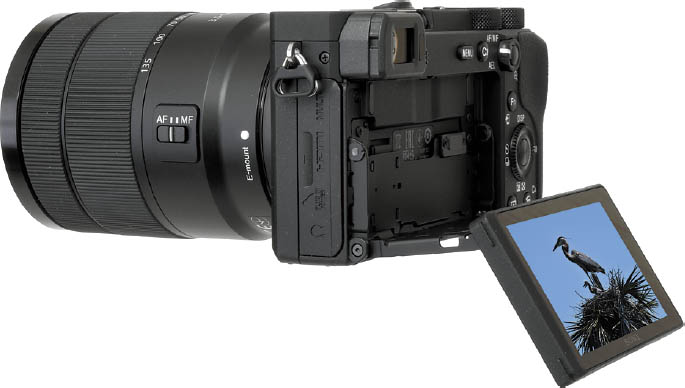
Figure 2.5 Tilting LCD.
Using the Touch Screen/Pad
Fortunately, even though your camera’s controls are squeezed into a smaller space, Sony has added valuable tools—including the a6600’s touch screen/touch pad—to streamline many of the most frequent operations. The dual screen/pad nomenclature is applied to the LCD monitor because the touch features of this camera can be used in three different ways. Only one can be active at one time, and can be specified using the Function of Touch Operation entry in the Camera Settings II-09 menu, as described in Chapter 4.
To activate the touch screen/pad, Sony forces you to jump between several different menus. Your first step is to enable Touch Operations. Visit the Setup 2 menu, select Touch Operation, and choose On. Then, access the Camera Settings II-09 menu, navigate to the Function of Touch Operation entry, and select one of these three functions: (If you need help navigating the a6600’s menu system, you’ll find directions at the beginning of Chapter 3.)
- Touch Shutter. If you select Touch Shutter in the Function of Touch Operation entry of the Camera Settings II-09 menu, when you compose your images using the LCD monitor to compose your photos, you can tap the screen to specify the focus point. The camera will then immediately take a picture. While Touch Shutter is enabled, you can activate it or deactivate it by tapping the icon shown at upper right in Figure 2.6. When the feature is activated, the dark bar that appears to the left of the icon turns orange.
The Touch Shutter feature is useful for capturing bursts of images when Drive Mode is set to Continuous Shooting, and for bracketing when Continuous Bracketing is enabled. Just keep touching the screen during the burst, and remove your finger to stop capture. Touch Shutter is unavailable when using the viewfinder, or Movie, S&Q Motion, or Manual Focus modes; when using Flexible/Expand Flexible Spot, Tracking: Flexible/Expand Flexible Spot Focus Area modes; or Digital or Clear Image Zoom.
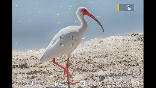
Figure 2.6 Tap or slide your finger across the screen to focus; tap the cancel icon (at upper right) to turn off Touch Focus.
- Touch Focus. When you select Touch Focus in the Function of the Touch Operation entry, you can tap the LCD screen and select a focus point or zone anywhere that the a6600 is able to achieve autofocus (that is, most of the frame other than the edges).
- If using the LCD monitor to compose: Tap the screen or hold down your finger and slide the focus area around within the frame. The camera will focus at that point.
- If using the viewfinder to compose: Touch the LCD screen and move the focus point around while looking through the viewfinder. The a6600 will focus on the point you select.
- When using manual focus: Double-tap the LCD to activate the focus magnifier.
In any case, the focus area will remain at that position, and the a6600 will focus when you press the shutter release down halfway. You can deactivate touch focus by pressing the Center button (described in the next section), or by tapping the “cancel focus” icon (a pointing finger with an X next to it) that appears at upper right on the screen. A quick tap may not register; this function requires a firm press. I’ll explain the various AF-area modes in Chapter 8.
Note: Like Touch Shutter, Touch Focus is not available when Focus Area is set to Flexible Spot or Expand Flexible Spot modes. However, you can still move the focus frame around. In Movie mode, Spot Focus can be used, but only when working with the LCD. Touch Focus is not available when using Digital Zoom, or with A-mount lenses when using the LA-EA2 or LA-EA4 adapters.
- Touch Tracking. With the Function of Touch Operation set to Touch Tracking, you can specify a subject that will be tracked by tapping the LCD monitor. Tracking will start and continue until you press the Center button or tap the Cancel Tracking icon in the upper-right corner of the LCD monitor. The camera will focus on the tracked subject when you press the shutter release down halfway. Note that this feature is not available with Hand-held Twilight and Anti-Motion Blur Scene modes (which each capture multiple images and combine them); when using Manual Focus modes; with Smart, Clear Image, or Digital zoom features; and when using the LA-EA2 or LA-EA4 lens adapters. It is also disabled in Movie mode when Record Setting is set to 120p/100p.
Touch Panel or Touch Pad?
The LCD monitor can function in one of two modes—or you can activate both modes at the same time. The options are available from the Touch Panel/Pad entry of the Setup 3 menu.
- Touch Panel+Pad. When you select this option, the a6600 switches between the two modes described next; when you are composing your image on the LCD monitor, the screen functions as a Touch Panel. If you bring the camera up to your eye, the screen switches to Touch Pad mode. This gives you the flexibility of using either mode if you decide both might be useful in a given shooting session. The descriptions of the panel and pad modes that follow will help you choose.
- Touch Panel Only. When touch panel mode is active and you’re using the LCD monitor to compose, you can touch the LCD monitor screen to specify the focus area (similarly to Touch Focus, described earlier).
- Touch Pad Only. When touch pad mode is active and you’re using the electronic viewfinder to compose, you can touch the LCD monitor screen to specify the focus area. You don’t have to tap the exact area (actually, that’s impossible, because you’re not actually looking at the LCD) if you use Relative Positioning, described in the next section. Instead, when you touch the pad, a focus point appears in the viewfinder relative to the location on the LCD. As I’ll explain shortly, that mode is useful because you can change the size of the sensitive area of the LCD screen. Once the focus area is specified (shown as cyan and yellow brackets in Figure 2.7), keep your finger on the screen and slide it around to the position you want, using your view through the EVF as your reference.
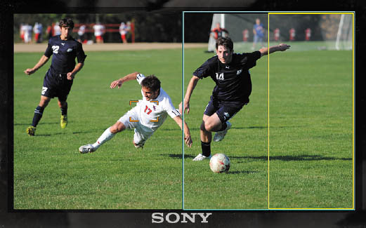
Figure 2.7 Right 1/2 (cyan) and Right 1/4 (yellow) touch pad areas. You can also specify Left 1/2, Left 1/4, and Upper or Lower Right or Left.
Before you wax ecstatic about these touch features, you’ll want to know that they are limited to the ability to specify a focus point when shooting stills and videos. You can’t select menu entries, type in text, scroll through playback views, or pinch/expand with your fingertips to zoom in and out during image review. However, the focusing features are quite useful, especially when shooting movies, as they allow selecting a focus area with a gentle tap. You have additional options for the touch pad, discussed next.
Touch Pad Options
Three touch pad options are available from the Setup 3 menu. Here is an overview of the adjustments you can make, and why you might want them.
- Operation in Vertical Orientation. Here you can specify whether touch controls are available when the camera is oriented in the vertical position (On), or only when the camera is held in horizontal orientation (Off). The touch feature can be a little awkward to use when rotated vertically, so some prefer to disable touch control for that mode.
- Touch Position Mode. Choose Absolute Position to allow you to quickly move the focusing frame to a distant position on the LCD. This setting automatically changes the Operation Area (described next) to encompass the full screen. Use Relative Position to move the focus point relative to the location on the LCD. That is, if you tap the center of the sensitive area, the focus point appears in the center; tap to the right or left, and the focus area appears to the right or left side.
- Operation Area. By default, the entire touch pad is sensitive when using the EVF, and that works well for most people. However, if your left eye is dominant (i.e., you’re “left-eyed”), your nose will touch the screen, and the a6600 registers that as a finger press. You can select Whole Screen if you want to make the entire LCD sensitive to touch pad operations.
To limit the sensitive area, you can choose the right or left 1/2 or 1/4 of the screen, or upper/lower right or left corners. The “relative” orientation remains the same, but it is limited to that reduced area. As noted, if you selected Absolute Position above, the entire screen is used, regardless of your setting here.
LCD Monitor Data Displays
The Sony a6600 provides a tilting and expansive 3-inch color LCD with high resolution to display everything you need to see, from images to a collection of informational data displays. Some of the data is shown only when you are viewing the Display All Info screen, but even then, not every item of data will be available all the time. (See Figure 2.8.) As discussed earlier, the electronic viewfinder display options provide much less data to avoid cluttering the live preview with numerals and icons during serious photography. Note: when you tilt the LCD monitor away from the camera body, the viewfinder is disabled, because the camera assumes you will be composing your image and performing other functions only with the LCD.
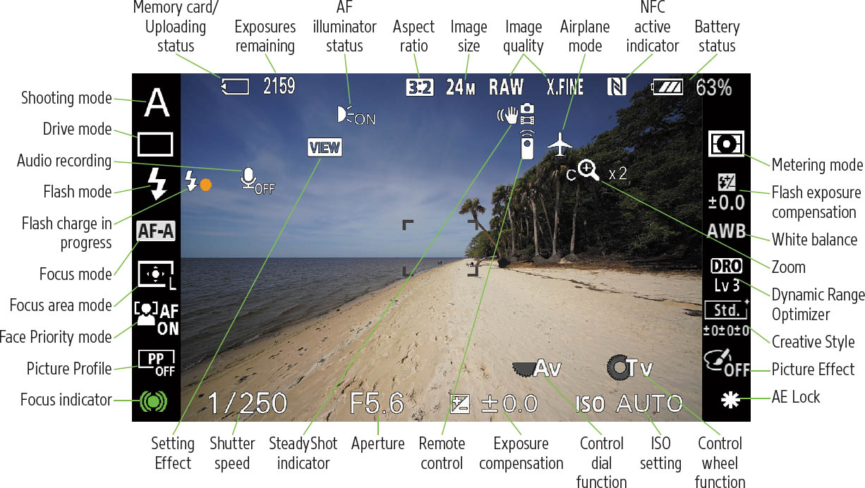
Figure 2.8 The Display All Info screen on the LCD.
While it is not possible to describe all the dozens of icons available for the LCD screen (indeed, it’s not possible for all the icons shown in Figure 2.8 to appear simultaneously), you’ll find all of them shown on pages 38 to 43 of the Sony Help Guide. The following is a description of the most important information that the camera can display in the LCD in Display All Info screen when it’s set for P, A, S, or M mode; less data is available in other display modes and when other Shooting modes are being used. The For Viewfinder/Quick Navi text-only displays (shown only on the LCD monitor and not in the viewfinder) are pictured in Figures 2.9 and 2.10.
- Shooting mode. Shows whether you’re using Program Auto, Aperture Priority, Shutter Priority, Manual, Panorama, one of the scene modes, or one of the two Auto modes.
- Memory card/Uploading status. Indicates whether a memory card is in the camera. (If you remove the card, a blinking NO CARD indicator will appear instead.) If the camera is connected using Wi-Fi, the indicator will display icons representing the upload status.
- Exposures remaining. Shows the approximate number of shots available to be taken on the memory card, assuming current conditions, such as image size and quality. When shooting a movie, the recordable time remaining is shown instead.
- Aspect ratio/Image size. Shows whether the camera is set for the default 3:2 aspect ratio or optional 4:3, 1:1, and wide-screen 16:9 aspect ratios (the image size icon changes to a “stretched” version when the aspect ratio is set to 16:9), and whether you’re shooting Large, Medium, or Small resolution images. When the camera is not set to the default 3:2 aspect ratio, wider black bands at the top and the bottom appear appropriate to the selected format.
- Image quality. Your image quality setting (JPEG Extra Fine, JPEG Fine, JPEG Standard, RAW, or RAW & JPEG) is displayed.
- NFC active indicator. Shows when your a6600 is linked to another device using Near Field Communications.
- Battery status. The remaining battery life (in percent) is indicated by this icon.
- Metering mode. The icons represent Multi, Center, or Spot metering. (See Chapter 9 for more detail.)
- Flash exposure compensation. This icon is shown whenever an external flash is active to indicate the level of flash exposure compensation, if any, that you have set.
- White balance. Shows current white balance setting. The choices are Auto White Balance, Daylight, Shade, Cloudy, Incandescent, Fluorescent, Flash, Color Temperature, and Custom. I’ll discuss white balance settings and adjustments in Chapter 4.
- Dynamic Range Optimizer. Indicates the type of dynamic range optimization (highlight/shadow detail enhancement) in use: Off, Auto DRO, and levels 1–5 of DRO.
- Creative Style. Indicates which of the Creative Style settings (Standard, Vivid, Neutral, Clear, Deep, Light, Portrait, Landscape, Sunset, Night Scene, Autumn Leaves, Black-and-White, or Sepia) is being applied.
- Picture Effect. Shows which of the special effects, such as Toy Camera, Pop Color, or Posterization, is being applied. I’ll explain these options in Chapter 3.
- SteadyShot indicator. Provides information as to whether the image stabilizer is On or Off and warns you that the shutter speed will be too long for the stabilizer to fully compensate for camera shake.
- Flash charge in progress. This lightning bolt icon appears on the screen when the flash unit is active; a solid orange dot beside it indicates the flash has recycled (charged) and is ready to fire.
- AF illuminator status. This icon appears when conditions are dark enough that the AF Illuminator will be needed to light up the area so that the autofocus system can operate properly.
- Flash mode. Provides flash mode information when an external flash is active. The possible choices are Flash Off, Autoflash, Fill Flash, Slow Sync, Rear Curtain, and Wireless. Not all these choices are available at all times. I’ll discuss flash options in more detail in Chapter 13.
- Drive mode. Shows whether the camera is set for Single-shot, Continuous shooting, Self-timer, Self-timer with continuous shooting, or Exposure bracketing. There is one additional option available: Remote Commander, which sets up the camera to be controlled by an infrared remote control.
- AE Lock. Appears when autoexposure has been locked at the current setting.
- ISO setting. Indicates the sensor ISO sensitivity currently set, either Auto ISO or a numerical value. I’ll discuss this camera feature in Chapter 9.
- Exposure compensation. This indicator shows the amount of exposure compensation, if any, currently set.
- Aperture. Displays the current f/stop set by the camera or, in Manual or Aperture Priority mode, as set by the user. If you’re viewing the Graphic display, icons indicate that wider apertures produce less depth-of-field (a “blurry” background) while smaller apertures provide a greater range of acceptable sharpness (increasing the odds of a more distinct background).
- Shutter speed. Shows the current shutter speed, either as set by the camera’s autoexposure system or, in Manual or Shutter Priority mode, as set by the user. If the camera’s Graphic display is used, the screen illustrates that faster shutter speeds are better for action and slower speeds are fine for scenes with less movement.
- Focus indicator. Flashes while focus is underway, and turns a solid green when focus is confirmed.
- Focus mode. Shows the currently selected focus mode, such as AF-S, AF-C, DMF (Direct Manual Focus), or MF (Manual Focus), as explained in Chapter 9.
- Focus area mode. Displays the active focus area mode, such as Wide, Zone, Center, or Flexible Spot, as explained in Chapter 9.
- Face Priority mode. Shows status of Face Detection mode (on/off). When the feature is activated, the camera attempts to detect faces in the scene before it, and, if it does, it adjusts autofocus, exposure, and white balance accordingly. When the Face Registration feature is also in use, the camera can detect a face that you have registered as a favorite. The camera can also use Eye AF to locate and focus on human eyes found within the frame, as long as you’re using Single Autofocus (AF-S). Autofocus options are discussed in more detail in Chapter 8.
- Picture Profile. If you’ve specified a picture profile image customization setting in Camera Settings I-12, your choice (from PP1 to PP10) is indicated here. I discuss picture profiles in Chapter 3.
- Zoom. Shows when digital zoom modes are active.
- Setting Effect. Indicates whether the LCD shows the effects of any adjustments, including exposure, white balance, or Picture Effects in Shooting mode.
- Audio recording. Shows whether sound recording is enabled/disabled for movie shooting.
- Airplane mode. Appears when Airplane mode has disabled Wi-Fi and NFC communications.
- Control dial/Control wheel function. Indicates whether the control dial or control wheel is used to adjust aperture (Av) or shutter speed (Tv).
- Remote control. Indicates that the camera’s infrared remote control function is active.
Using the Quick Navi Function Menu
If you select the For Viewfinder screen by pressing the DISP button until it appears, the LCD monitor shows the For Viewfinder display, with only the data and no live view of the scene, as you can see in Figure 2.9. Press the Fn button to switch to the Quick Navi screen (see Figure 2.10). You can then use the left/right/up/down directional controls to highlight any of the settings that are not grayed out.
Once an option is highlighted, you can rotate the control wheel to change its settings quickly or press OK (the center button) to produce a screen with all the options. Use the directional buttons and the OK button to select the option you want. The Quick Navi screen is, in effect, a more fully featured Function menu. When the Quick Navi display is visible on the LCD monitor, you must compose images using the electronic viewfinder.
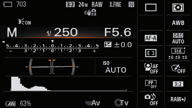
Figure 2.9 The For Viewfinder/Quick Navi information screen is available only for the LCD monitor and is not shown in the viewfinder.
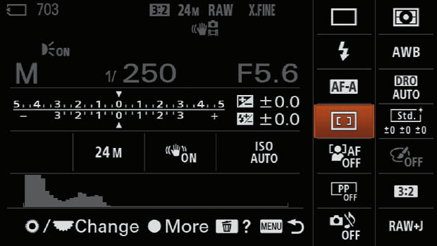
Figure 2.10 The Display All Info screen on the LCD.
Going Topside
The top surface of the a6600 has several frequently accessed controls of its own. They are labeled in Figure 2.11:
- Focal plane indicator. Precision macro and scientific photography sometimes requires knowing exactly where the focal plane of the sensor is. The symbol etched on the top of the camera marks that plane.
- Multi interface shoe. This “standard” accessory shoe is used for electronic flash units and contains extra electrical contacts for use with Sony-brand microphones, such as the Sony ECM-XYSTM1 microphone, Sony-compatible electronic flash, and other accessories. However, it is also compatible with the ISO-518 hot shoe used by virtually all other camera manufacturers. While other flashes can be attached and fired, only Sony-compatible units can take advantage of wireless operation, through-the-lens (TTL) metering, and other options.
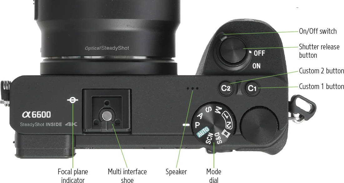
Figure 2.11
The multi interface shoe replaces the non-standard Minolta-style proprietary “iISO” shoe used by Sony for many of its cameras until about 2012. The older shoe required adapters to use non-Sony accessories. The new multi interface connector can still be used with older Sony flash units and accessories, but it requires an adapter of its own for backward compatibility. If you own no older Sony electronic flash or accessories, you can simply move forward and purchase gear for the new, more standard hot shoe.
- Mode dial. Rotate this dial to select Shooting modes including Manual exposure, Shutter Priority, Aperture Priority, Program Auto, Intelligent Auto, Slow Motion/Quick Motion (S&Q), Movie mode, and the Memory Recall positions, numbered 1 and 2 (which allow you to choose predefined groups of settings for each, as described in Chapter 6).
- On/Off switch. Rotate to the right to turn the camera on; to the left to switch it off.
- Shutter release button. Partially depress this button to lock in exposure and focus. Press it all the way to take the picture. Hold this button down to take a continuous stream of images when the drive mode is set for Continuous shooting. Tapping the shutter release when the camera’s power save feature has turned off the autoexposure and autofocus mechanisms reactivates both. When a review image or menu screen is displayed on the LCD, tapping this button removes that display, returning the camera to the standard view and reactivating the autoexposure and autofocus mechanisms.
- Custom 1 button. By default, this summons the white balance menu. The Custom 1 button can also be re-defined to perform any of several different functions, such as metering mode, creative style, drive mode, focus mode, flash mode, flash compensation, focus area, exposure compensation, and more than 50 (count ’em!) other behaviors. You can also select Not Set to deactivate it entirely. In Chapter 4, I’ll show you how to redefine this button in the Custom Key Settings entry of the Camera Settings II-09 menu.
- Custom 2 button. By default, this button activates focus area (described in more detail in Chapter 8) but can be redefined to other functions.
Underneath Your Sony a6600
The bottom panel of your a6600 has only a few components, illustrated in Figure 2.12.
- Tripod socket. Attach the camera to the Sony VG-C4EM vertical grip, flash bracket, tripod, monopod, or other support using this standard receptacle. The socket is positioned roughly behind the optical center of the lens, a decent location when using a tripod with a pan (side rotating) movement, compared to an off-center orientation. For most accurate panning, the socket would ideally be placed a little forward (in front of the camera body) so the pivot point is located under the optical center of the lens, but you can’t have everything. There are special attachments you can use to accomplish this if you like.
- Vertical grip alignment holes. These two small depressions are located on either side of the battery door with matching nubs on the vertical grip to ensure correct alignment as the grip is attached to the bottom of the camera.
- Battery compartment door. Slide the door open to access the battery.
- Access lamp. Flashes red when the a6600 is writing to the memory card. It’s located adjacent to the battery/memory compartment to remind you that you should not remove the card while it is flashing!
- AC adapter access door. This flap opens to allow an accessory, such as the dummy battery supplied with the NPA-MQZ1K Multi-Battery Adapter Kit shown in Figure 1.5 in the previous chapter to link to an AC or DC current source.
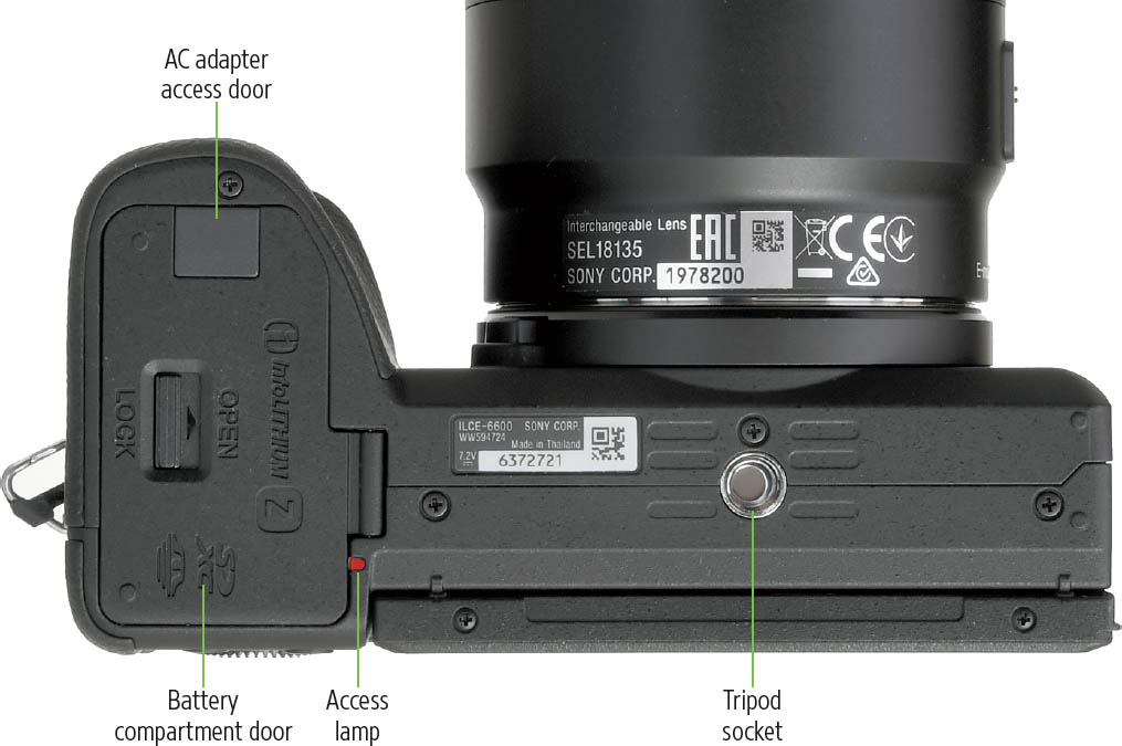
Figure 2.12