
The programming language that I chose was JavaScript. This is because it is already well supported on the BeagleBone as it comes to you from the supplier. You can access the Cloud9 integrated development environment (IDE) from the Start.html link on the microSD card image.
There are plenty of very good tutorials and videos on how to use the Cloud9 IDE, so I have not included one here.
What the software does is, it watches an input pin waiting for it to go low. If the pin goes low, the software makes an output pin go high. This simulates an alarm panel monitoring a set of contacts, waiting for an alarm to occur.
In order to turn the alarm off, the software monitors another pin. If this pin goes low, it turns the alarm off. This is to simulate an alarm key switch being turned to the disarm position, but any type of contact closure will do.
Tip
Downloading the example code and image files
You can download the example code and image files for all Packt books you have purchased from your account at http://www.packtpub.com. If you purchased this book elsewhere, you can visit http://www.packtpub.com/support and register to have the files e-mailed directly to you.
We won't be building and testing the actual alarm system hardware until the following chapters, so for now, we will build ourselves an "alarm system simulator". In order to do that, I built the following circuit.
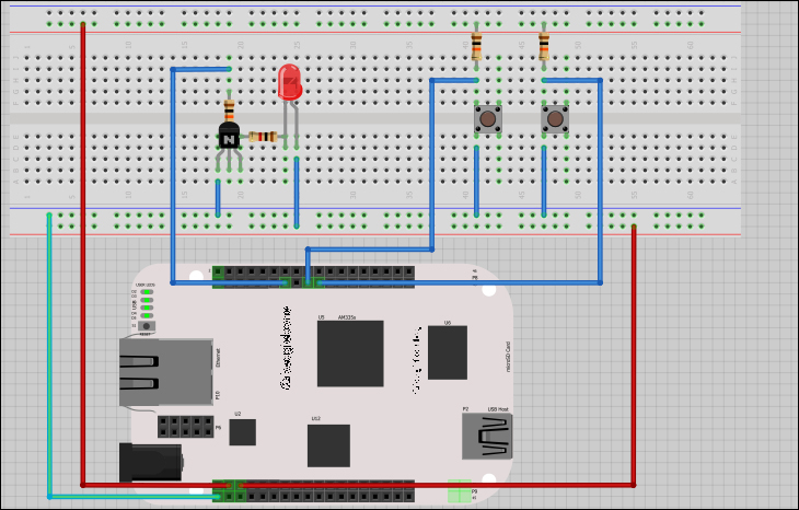
Breadboard layout
The following schematics will show in more detail how the circuit was constructed. The 3.3V power comes from the BeagleBone connector—P9 pin 3. The 5V power comes from P9 pin 5 and the ground is P9 pin 1.
As I said before, all that the alarm system does is monitor contacts and take the appropriate action. The system doesn't know or care what is ''behind'' the contacts. To make it easier for the reader to understand, I have labelled the switches—Alarm In to simulate door or window contacts, and Alarm Reset to simulate the alarm reset button or the switch.
In the following diagram, the BeagleBone connector number and pin numbers are indicated by the flags attached to the circuit drawing. For example, P8-13 in the simulated siren drawing means pin 13 of connector P8 on the BeagleBone.
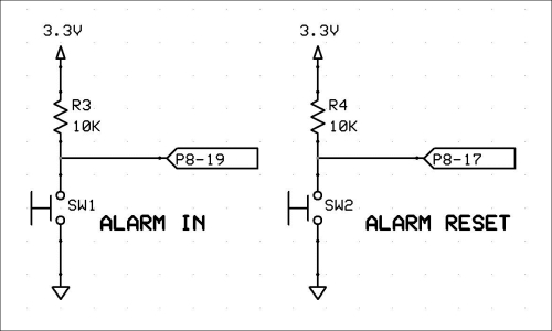
Simulated alarm contacts
In order to simulate an alarm bell or siren, I connected an LED to the alarm output pin. When the software detects an alarm, it will turn on the LED. We will be using a transistor on the outputs of the BeagleBone to boost the current capability of the output, and to hopefully protect the BeagleBone from external wiring errors. Note that the transistor also allows us to power the LED from 5V instead of 3.3V.
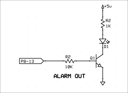
Simulated siren