
The DC-motor driver circuit will drive two DC motors, and unlike the solenoid driver, this board can control the motors separately. You can also connect it directly to the 3.3V outputs of the BeagleBoard adapter board. The PCB has been designed so that it fits between connectors J8 and J9 on a BeagleBone prototype board. Expansion boards are stackable on the BeagleBone, so it should be possible to put this board above or below your alarm system boards.
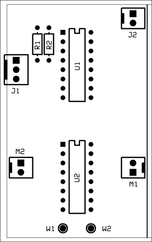
The DC motor control board
In this case, the motor will be powered continuously as compared to the solenoid, which is pulsed. For this reason, it will be a good idea to install a heat sink on U2.
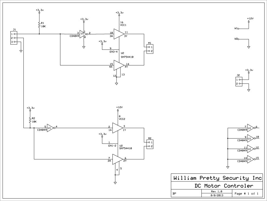
In the preceding diagram, you will notice that the motor driver IC, U2, has two VCC inputs. The VCC input is the power supply input to an IC, which normally has only one supply input. The great thing about SN754410 is that it has two supply inputs. One for the control logic, in this case 3.3V, and one for the output driver circuit (12V). In this way, we can control a 12-volt device with 3.3-volt logic.
What the DC motor does is up to you; for example, a 12-volt bilge pump, a fountain pump in your garden, or perhaps some low-voltage LED lighting.