
Pulsed electric field (PEF) systems for commercial food and juice processing
Abstract:
This chapter describes the key PEF treatment parameters, and the specialized equipment required to implement this process in liquid food processing. It also describes the interactions between the process parameters and the electrical design and performance of PEF systems, as a guide for potential adopters of this technology. Finally, this chapter presents initial commercial applications of PEF processing, and guidelines for its future adoption.
4.1 Introduction
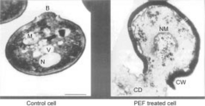
Pulsed electric field (PEF) processing is a low temperature, non-thermal, non-chemical, low impact process that achieves very high kill rates, making PEF processing a practical alternative to thermal pasteurization. PEF processing involves the application of short duration (1–20 μs), very high voltage pulses that create a high voltage field (approximately 20–50 kV/cm) across a liquid food to kill resident bacteria, molds, and other microorganisms via electroporation of the cell membrane (Fig. 4.1). The pulses are so frequent that all of the liquid in a pipe can be treated as it flows through the treatment chamber. By using multiple treatment chambers to apply pulses to a stream of fluid in a continuous flow process, kill ratios of 5–9 log reductions, similar to those resulting from pasteurization, have been achieved. Unlike pasteurization, however, the food is not heated during PEF processing, so its taste and nutritional value remain essentially indistinguishable from fresh, untreated product – while maintaining the level of food safety associated with pasteurization. PEF processed products simply taste fresher than pasteurized products, yet have equivalent safety and shelf life.
Multiple experiments have demonstrated that the shelf life of PEF processed food is comparable to that yielded by pasteurization, with no or very minimal impact on the taste, color, or nutritional value of the food. PEF processing is particularly beneficial to fresh juices, beer, and other foods that are susceptible to changes in their flavor caused by the heat of pasteurization. The commercial debut of PEF processing occurred in 2005, with Genesis Juice’s introduction of PEF processed juices to the consumer market. This represents the first known commercial introduction of PEF processed foods. Since that time, there has been considerable interest in the adoption of PEF processing, and research into process scale-up. In applications other than foods, PEF processing can also improve the performance of industrial processes such as the removal of water from sludge, or the extraction of sugars and starches from plants, because the ruptured cells release their intracellular liquids more easily into their surroundings. This chapter will describe the key PEF parameters, and the specialized equipment required to implement this process in liquid food processing. It will describe the interactions between the process parameters and the electrical design and performance of PEF systems, as a guide for potential adopters of this technology.
4.1.1 PEF utility
The origins of PEF processing are deep and varied. Researchers demonstrated that voltage fields could disrupt biological cells as early as I960, with microbial inactivation initially demonstrated in 1967. Only since the mid-1990s, however, has there been the necessary confluence of applied research, developments in high voltage equipment, and commercial interest in non-thermal processes to move PEF technology from the laboratory and into commercial operation. Three key steps in this development were the Dunn and Pearlman patent on the PEF process for disinfection (4,695,472) in 1987, the development of the co-field flow treatment chambers at The Ohio State University (OSU) in 1997, and the initial use of solid state, high voltage pulse modulators for PEF in 2000 (built by DTI for OSU). This combination of advances laid the groundwork for the substantial movement of PEF processing in the last decade from laboratory to commercialization.
PEF development has occurred in three primary, loosely related areas over this period: medical treatment, tissue disintegration, and disinfection. Research in these areas has been conducted separately, but with considerable cross-fertilization of results and processes. Among these areas, the use of high voltage fields for electroporation is probably most mature in the medical world. A Google search yields over one million hits for the term ‘electroporation’, with the vast majority related to medical and microbiological uses of this technique at the cellular level, and dozens of companies selling equipment specifically designed for electroporation. The well established method of medical electroporation is to apply pulsed voltage fields across living cells and open pores in cellular membranes for a short period as a means to extract or insert specific chemicals into the cell (for chemotherapy or genetic manipulation) without permanently damaging the cells themselves. The equipment required is typically very small in terms of voltage, power, and capacity, since medical electroporation is typically applicable to small samples (from a micro-liter to milli-liters). This line of activity has developed relatively independently of the other two major applications – disinfection and tissue disintegration.
PEF has also been investigated (and is currently being commercialized) as a technique for permeabilization of plant and animal tissues for a variety of purposes – typically focused on extraction, drying, or pre-processing of the tissue for subsequent chemical or microbial processing. In all cases, the electroporation-induced rupture of the plant or animal tissue cells opens these cells to allow the exchange of materials between the internal and external environment, such as the simplified release of water (enhanced drying) or internal materials (extraction of sugar from sugar beet), or the entrance of chemicals or microbes into the internal structure of the cell (accelerated fermentation). Several commercial installations using PEF have been reported, including the use of PEF for wastewater treatment (prior to anaerobic digestion of wastewater sludge), extraction, and drying. In general, the focus of these activities is process acceleration, reduction of energy costs, or both.
Disinfection is the primary application of PEF related to food products – using PEF to induce electroporation and kill microbes in liquid or pumpable foods. Generally, the desire has been to achieve disinfection levels similar to thermal pasteurization, but without the damage to taste, nutrition, and other characteristics of unprocessed liquids which can be significantly degraded by heating the food (i.e., thermal processing). In contrast to medical electroporation, disinfection requires that the voltage field be applied at a high enough intensity, and for a sufficient duration, such that the electroporation process does not just open the pores in the cell membranes, it ruptures the cell membrane irreversibly. In addition, this field must be applied to larger fluid volumes, and kill all of the microbes in those volumes, to achieve required disinfection levels.
Substantial research over the last 20 years has clearly demonstrated that PEF can achieve disinfection of liquids across a wide range of microbes and products, at relatively low temperatures compared to pasteurization (i.e., 20–50 °C). Literally thousands of studies, and a number of books, have been published showing the impact of PEF on microbes and foods in various combinations, under a wide range of treatment protocols. In general, these studies have focused on two related areas: showing microbial kill, and assessing the impact of PEF on food quality (taste, nutrition, etc.) across a wide range of pumpable products ranging from juices to semi-solids, such as sausages. A sampling of these reports show PEF research against a range of microorganisms, including pathogens, spoilage organisms, and surrogates for pathogens, including:
A primary result of these studies is that it is possible to achieve high microbial kill levels (as high as 9 logs, or only one survivor out of one billion initial microbes), with proper treatment conditions and careful processing. Given that the standard for pasteurization is typically a 5-log reduction in microbial survival, PEF is clearly capable of replacing pasteurization as a disinfection step. As this research moves towards commercial applications, a key area of interest has been balancing the competing factors of high levels of disinfection, with minimal impact on the taste of the food.
One key finding from these studies is that, to the best of our knowledge, PEF is only effective in killing vegetative microbes, yeasts, and molds – PEF appears ineffective against spores or viruses. This is not surprising, given that PEF is believed to work through the mechanism of electroporation, and spores and viruses do not have active membranes that the electric field can impact. For this reason, the preponderance of PEF studies focused on food disinfection have targeted acidic products, such as citrus juices and tomato sauces, where spore regeneration is not an issue. Researchers are still investigating the use of PEF, either by itself or in combination with other treatments, to kill resistant bacterial spores, but without notable success to date. This work, if ultimately successful, would significantly expand the applicability of PEF disinfection to a larger range of liquid foods.
There has also been considerable research on the applicability of PEF processing to a variety of liquid foodstuffs. The majority of this research has focused on fruit and vegetable juices, but successful PEF processing has been applied to products from beer to salad dressings and salsa, and even to sausage. As a result of this range of PEF application, there are several key product parameters that can be identified to select a potential candidate for PEF processing:
1. The product typically must be pumpable, but can be highly viscous. Treatment is applied as the product is flowing (i.e., pre-packaging).
2. It must be possible to remove bubbles from the liquid, either through de-aeration or pressure, to prevent arcing.
3. There can be particulates in the fluid (fruit and vegetable chunks, for example), so long as the treatment chambers are large enough to prevent clogging.
4. Acidified products are typically necessary if spore-forming microorganisms represent a pathogen or spoilage organism of concern.
In summary, PEF processing has made significant advances based on approximately the past 20 years of focused R&D using a wide range and variety of pathogens and spoilage organisms, potential products for PEF treatment, and equipment required to apply the PEF treatment. PEF is FDA approved for foods in the US, and the remaining barriers to PEF commercialization are primarily economic, relating to developing new products with increased value in terms of nutrition, taste, and quality) achieved through PEF processing, compared to the initial high costs of implementing PEF.
4.2 Key process parameters
Any discussion of PEF system design must be based upon an effective PEF treatment protocol. In designing a PEF system, this protocol (or at least its boundaries) must be known. The PEF treatment protocol must be known for a particular liquid food, targeting its associated potential pathogens and spoilage organisms (or other organisms of interest). The protocol is developed from experiments involving multiple trials at different electrical field strengths and durations, and followed by microbiological assessment of the inoculated food after PEF treatment. For example, a typical treatment protocol might require the application of a 35 kV/cm field for a minimum of 50 μs to yield a bacterial reduction (typically, a 5-log reduction) of a target organism (such as E. coli) in a liquid food substrate. Numerous protocols have been developed and published for a wide range of liquid foods, organisms, and PEF systems. For the purposes of designing a PEF system, we assume that the boundaries of the protocol are known. From that point, the food’s characteristics, and the desired processing capacity are the two major remaining considerations to be accounted for in the system design. These are typically expressed as the liquid conductivity and flow rate. These two factors, when combined with the desired protocol, form the basis for designing the PEF system.
4.2.1 Pulse shape
One critical issue in assessing PEF system performance is the pulse shape of a given PEF system. PEF is generally believed to work on a voltage threshold, and only exposure time above that critical field strength is believed to have the desired effect on killing target microorganisms. In an ideal PEF pulse, there would be zero rise and fall time, and the flattop of the pulse would be concentrated at a constant voltage. All of the pulse time and energy, therefore, would be at the desired voltage. In practice, however, this pulse shape is not attainable. All pulses have finite rise and fall times, where the full voltage is not present, and it is not possible to achieve a perfect stationary flattop. Characterizing the actual pulse voltage and time is therefore subject to arbitrary estimates (or, more commonly, ignored all together).
To illustrate this, Fig. 4.2 shows three normalized voltage waveforms for typical real pulses: a rectangular, exponential, and half-sine wave. These are simplified versions of three of the most common modulator pulse shapes. They all have the same peak voltage (Vmax = 100), and total pulsewidth (with the exponential cut off at approximately 25% Vmax). In this simplified example, researchers using each of these three waveforms could report results assuming these pulse characteristics (V = 100, t = 100) were the same. However, their total energy and time above any arbitrary threshold voltage varies dramatically. The total energy delivered, and the treatment time above a threshold voltage, could vary by more than a factor of six, depending on the pulse shape each researcher used. Given this disparity, it is not surprising that there are wildly different biological results reported by different researchers, for apparently similar to identical conditions. More specifically, compared to the ideal pulse, each of these pulse shapes has the characteristics shown in Table 4.1 (based on a threshold of 80% of Vmax). If it were possible to run for longer pulsewidths, these differences would begin to converge, but this is typically not the case with PEF systems. For shorter pulsewidths, the disparity between the ideal and actual pulse shapes becomes even greater, since more of the total pulsewidth consists of the rise and fall times, which, in essence, translates into wasted power that does not contribute to the PEF treatment. It is critical, therefore, to approximate the ideal waveform as closely as possible.
Table 4.1
Comparison of energy and time above 80% Vmax for an ideal pulse and the three voltage nominal pulses in Fig. 4.2
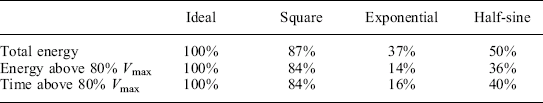
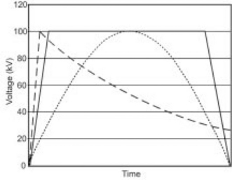
Fig. 4.2 Three normalized PEF voltage pulses – square wave, half-sine wave, and decaying exponential. Although each pulse has the same nominal peak voltage and pulsewidth, the total energy and time above any voltage threshold voltage vary substantially.
Defining treatment protocols, therefore, requires knowledge of both the pulse shape and measurement thresholds. Figure 4.3 shows PEF voltage and current pulses from a Diversified Technologies, Inc. pilot-scale PEF system processing orange juice. The DC voltage setting is 24 kV, and this peak voltage is maintained for just under 2 μs in this example. The commanded pulsewidth (at the input pulse command) is approximately 2.5 μs, and the 0.5 μs difference is attributable to the pulse risetime. The total pulsewidth, taking into account both rise- and fall-times, could be interpreted to be as long as 3 μs. If 20 pulses are applied to each element of the juice, the reported treatment time could vary between 35 and 60 μs. Similarly (but less significantly for this case), the peak voltage could be reported as several kV above or below the nominal 24 kV, depending on where the measurement is made during the pulse. How these parameters are reported significantly impacts the results when attempting to replicate protocols on different PEF systems, with different pulse shapes.
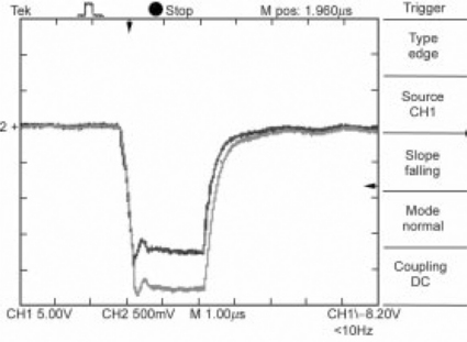
Fig. 4.3 PEF voltage and current waveforms from DTI’s pilot PEF system into orange juice. Pulse parameters are 2 μs pulsewidth, 24 kV, 45 A, but could be reported as up to 3 μs in pulsewidth, and 20–26 kV in voltage, depending on how the pulse is characterized.
There is a strong need within the PEF research community to standardize the reporting of PEF results, allowing data from different organizations, using different PEF systems and waveforms, to be compared and assessed on a common basis. At a minimum, the voltage pulse shape should be shown, with measurement points for peak voltage and pulsewidth. This would allow other PEF researchers and process developers to make their own adjustments between systems.
4.2.2 Conductivity/flow rate
The power required to apply a given protocol is determined by the conductivity of the fluid, and the desired flow rate. Conductivity is a measure of the electron mobility within a volume of material – a measure of how easily it passes electrical current. Conductivity is expressed as Siemens/meter (S/m), or, to get to whole numbers for typical fluids, mS/cm. It is the reciprocal of resistivity, which is the electrical resistance of a volume of material. In most PEF research, conductivity (σ) is used as a measure because it is readily measured, applicable to the liquid itself, and allows calculation of the current that will pass through a volume of fluid through application of Ohm’s law. Sample conductivities (ms/cm) are shown in Table 4.2.
Table 4.2
Conductivities of common liquids
| Liquid | Conductivity (ms/cm) |
| Apple juice | 1.75 |
| Water (tap, distilled) | 0.0011 |
| Liquid eggs | 5.88 |
| Orange juice | 3.3–5.5 |
| Beer | 1.5 |
| Milk | 3.2–5.8 |
| Yogurt | 6.0 |
The electric field (in V/m or more commonly, kV/cm) is set by the treatment protocol, so the energy required to deliver this field to a volume of liquid is a direct function of the fluid conductivity. Since power is energy over time, the energy required per liter, and the number of liters to be processed per unit time, give the total average power required in the PEF system. A 100 kW average power system can process five times the volume of product per hour as a 20 kW system, for the same protocol. The power required increases linearly with flow rate and conductivity for a given protocol, and by the square of the required field strength – making field strength the most critical parameter to establish correctly, in order to minimize electrical power requirements in the PEF process.
Adapting to high flow rate is the key to commercial scale-up of PEF systems. A laboratory PEF system typically processes liters per hour (or less), and a pilot plant typically operates at tens to hundreds of liters per hour. Commercial systems, however, must be capable of processing thousands to tens of thousands of liters per hour – representing two to three orders of magnitude higher throughput than a pilot system. Fortunately, research at Ohio State University (OSU) and other organizations has demonstrated that the PEF process itself operates independently from flow rate – so long as the field strength and dose (total treatment time) are maintained. This allows treatment protocols developed in laboratory and pilot scale systems to readily transition to commercial scale PEF operations.
Flow rate determines several other major PEF system characteristics. For the most common treatment chamber design, the co-field flow chamber (discussed below), the diameter of the treatment chamber must be sized to pass the desired flow at reasonable pressure drops. The presence of particulates and ‘chunks’ in the flow can also impact the sizing of the chamber. At the same time, to achieve uniform field strength within the treatment chamber, the gap across which the voltage is applied must increase with pipe diameter (maintaining the gap at more than 1.2 × the diameter provides reasonably uniform fields). Larger gaps require lower fluid pressure in the treatment chambers, but require higher absolute voltages to maintain a given field strength. For example, doubling the treatment chamber diameter allows four times the flow at a given pressure, but requires twice the length and peak voltage (and also twice the average current) to maintain the same field strength and treatment time.
The final parameter to be assessed in the design of a PEF system is the required pulse frequency. The total energy delivered to a liter of fluid is known from the treatment protocol. As more liquid is processed, the average power goes up linearly. In conventional pulsed power systems, increasing the average power is typically achieved by increasing the pulsewidth, allowing the pulse frequency to remain at reasonable levels. For PEF systems, however, it is generally not possible to run at pulsewidths longer than approximately 10 μs before arcing occurs. Without the ability to increase the pulsewidth, the only remaining options are to increase the energy in each pulse (which directly increases the cost of the PEF system), or to operate with more pulses per second (increased pulse frequency). This need for higher pulse frequencies becomes critical as PEF systems are scaled to commercial flow rates, as discussed in the next section.
4.3 Pulsed electric field (PEF) system overview
There are three unique elements to a PEF system, in comparison to a traditional pasteurizer. First, a DC power supply (Fig. 4.4) transitions the AC power available from the utility into high voltage, DC power. The second major element of the PEF system is the pulse modulator, which transforms that DC power into short, high peak power pulses. Finally, there is the treatment chamber, where the high voltage pulses are applied to the liquid itself. The next sections describe each of these subsystems, with general assessments of the alternatives available.
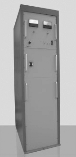
Fig. 4.4 150kW DC power supply for the PEF system shown in Fig. 4.15.
4.3.1 Power supplies
A DC power supply converts the AC power available from the utility into high voltage, DC power. DC power supplies are typically rated in terms of their average power (in Watts). There are three basic DC power supply architectures. The simplest is a transformer-rectifier, which operates at line frequency (50–60 Hz). These supplies are the least expensive, but can be very large at high power, and have significant drawbacks in terms of voltage regulation, voltage control, and their impact on the overall plant power system. They are, however, very inexpensive on a ‘$ per Watt’ basis, especially at high power levels (hundreds of kW).
The second basic power supply architecture is a switching power supply. In this design, the input power is rectified and ‘chopped’ at high frequency (10–50 kHz) into a transformer rectifier. Since the size of the transformer decreases as the chopping frequency increases, it is possible to build very compact, high power DC supplies in this way. Switching supplies provide highly regulated and rapidly adjustable output voltage, which supports tight control of the PEF process parameters, independent of the modulator architecture. Switching power supplies are typically used in applications requiring up to ~ 500 kW, which supports PEF processing up to flow rates of approximately 10 000 l/hr – sufficient for most anticipated commercial lines. The drawback of switching power supplies is their cost, which can be 2–5 times higher than simple transformer rectifiers of similar power.
At very high power levels (500 kW and above), the optimal solution is often the combination of a transformer-rectifier (for unregulated power) with a high frequency voltage regulator, such as a buck regulator, on the output to provide the final voltage control. This class of power supplies appears to be most applicable to very high throughput PEF processing, such as for large-scale commercial food processing and wastewater treatment.
4.3.2 Modulators
The design and construction of PEF pulse modulators builds on over 50 years of R&D into pulse modulators for other applications, including radar and particle accelerators. Ideally, the modulator for a PEF system will provide pulses of very consistent voltage, with fast rise and fall times, at any desired pulsewidths and pulse frequencies needed for the desired PEF process parameters. The desirability of a modulator design is typically based on how well it meets these criteria.
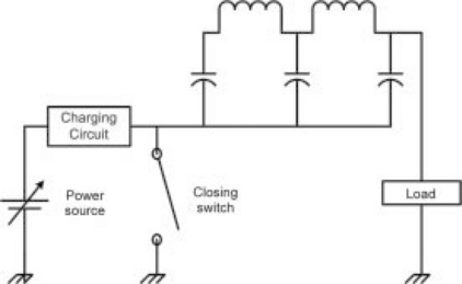
All pulse modulators are based on the ability to switch electricity very rapidly. This can be done mechanically, although this is slow and difficult to operate at any frequency, and not compatible with PEF processing. It can be done by creating a controlled short circuit, in a device such as a spark gap, thyratron, or using a solid-state device such as a Silicon Controlled Rectifier (SCR). This is referred to as a closing switch (Fig. 4.5). Closing switches must be able to remain open, holding off the full input voltage, until they are commanded to close. When they are closed, current will continue to flow through the switch until the input power is dissipated. Typically, closing switches must wait until there is zero current (or a reverse voltage) in order to open again, and prepare for the next pulse.
This switching can also can be accomplished by allowing current to alternately flow and be interrupted, using a vacuum tube (such as a tetrode) or a power transistor, such as an Insulated Gate Bipolar Transistor (IGBT). In these opening and closing switches, current can be turned both on and off at any time, but the switch must be able to withstand the stresses of opening under full current, as well as holding the full voltage when open.
Along with the two classes of switch (closing, and opening and closing) there are three fundamental modulator designs available – pulse forming networks (PFNs, Fig. 4.5), ‘hard switches’ (Fig. 4.6), and transformer coupled systems (Fig. 4.7). All of these designs have their origins in the days of vacuum tube-based modulators, but they have transitioned to solid-state switches in place of vacuum tubes over the past decade.
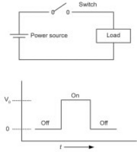
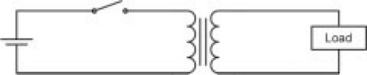
Fig. 4.7 Transformer coupled modulator with opening and closing switch. Transformer coupled modulators are also possible with PFNs on the primary, rather than an opening and closing switch.
The pulse forming network (PFN) shown in Fig. 4.5 holds a predetermined amount of energy in its capacitors, and creates a shaped pulse through the combination of capacitors and inductors in the network. This allows modification of the pulse parameters, such as risetime and pulsewidth, but only by manually changing the values of the capacitors and inductors themselves. For best performance, PFNs and transformer coupled systems must be impedance matched to the load – meaning that the voltage and current must have a single optimal relationship. Finally, after a pulse, the PFN must be completely recharged from a power supply, which can limit the frequency of pulses that can be generated with this design.
The alternative is to use a ‘hard switch’, capable of switching the full voltage on and off directly (Fig. 4.6). This has a number of benefits to PEF processing – it allows flexibility in both pulsewidth and pulse frequency, and, since these hard switches are typically low impedance, allows the modulator to provide a consistent, repeatable output voltage over the range of peak currents required as the food conductivity varies. Solid-state switches are ideally suited to both of these requirements. The trade-off is that the power supply must also operate at this full voltage. DTI has pioneered the use of solid-state hard switches for PEF and other applications (Fig. 4.8), with other designs emerging in recent years.
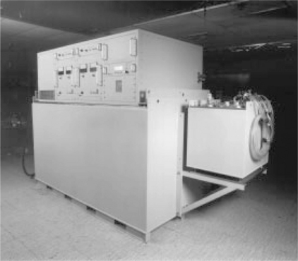
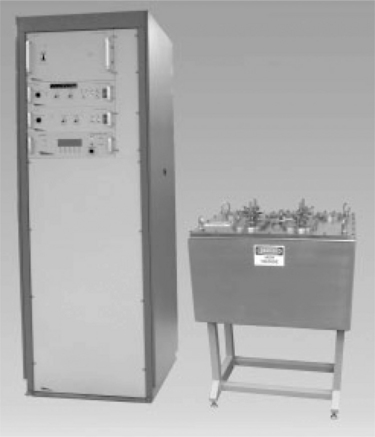
Fig. 4.8 60 kV Bi-polar solid state PEF system built by Diversified Technologies, Inc. (DTI) for OSU in 1999 under the Dual Use Science & Technology (DUST) PEF Consortium. This was the first commercial scale PEF system in the world. The power supplies and pulse modulators are in the large tank, with the treatment chambers in the smaller ‘sidecar’ tank. Controls are located above the unit.
The alternative to full voltage switching is a pulse transformer coupled design. In this design, the switching required to create a pulse occurs at relatively low voltage (typically less than 20% of the desired output voltage), and the resulting low voltage pulse is passed through a pulse transformer, which increases the pulse voltage by a factor related to the ratio of the primary to secondary turns in the transformer itself. This is a critical simplification when it is difficult or impossible to switch the high voltage directly – to create a 20 kV pulse, it is possible to use only a 2 kV switch, and a 10:1 turns ratio pulse transformer. The trade-off, however, is that the same energy must be present at both the primary and the secondary of the pulse transformer. This means that to create a 20 kV, 100 A pulse (2 MW peak power), the 2 kV switch must handle 1000 A to provide the same 2 MW of peak power. Transformer-coupled modulators have traditionally been built using a closing switch and a pulse forming network on the primary of the pulse transformer (the combination of Figs 4.5 and 4.7).
Alternatively, there is the ‘hybrid’ modulator, which combines a solid state hard switch at lower voltage with a pulse transformer (Fig. 4.7). In another design, multiple switches operate in parallel on multiple primaries, with each corresponding transformer secondary connected in series, to achieve high voltage. These designs eliminate several drawbacks of the PFN (e.g., fixed pulsewidth, limited frequency).
Independent of the primary pulse generation approach, the pulse transformer itself has a couple of drawbacks for PEF processing. First, the transformer core must be ‘reset’ between pulses to avoid core saturation (in a mono-polar system). This can require a second, reset pulser which must operate between high voltage pulses, limiting the pulse frequency available. Second, the pulse transformer typically wastes approximately 10% of the total power in the PEF system – turning it into unusable heat. The most critical factor, however, is that in PEF systems the load impedance can vary considerably. The liquid being processed is the load, and is therefore an integral part of the circuit. Its conductivity can vary by over an order of magnitude across different foods, and even a single food type, such as orange juice, can vary considerably in conductivity due to changes in the raw materials.
The simulated pulse shapes shown in Fig. 4.9 illustrate this effect. The PEF protocol and overall system design is shown in Table 4.3. In this case, we are applying 35 kV/cm to a treatment chamber with a gap (cell length) of 0.6 cm, which requires an applied voltage of 21 kV. There are a total of two chambers (four treatment zones). The risetime of the pulses are modeled at (from left to right) conductivities of 1, 3, and 5 mS/cm. In the upper set of pulses, we use a hybrid modulator based on pulse transformer ratio of 6:1, meaning that a 3.5 kV pulse is required on the primary of the pulse transformer for 21 kV pulse on the secondary.
Table 4.3
| Flow rate | 300liter/hr |
| Cell diameter | 0.5 cm |
| Cell length | 0.6 cm |
| Velocity | 424 cm/s |
| Transit time | 1.4 m/s |
| Minimum rep rate | 1768 Hz |
| Field | 35 kV/cm |
| Vsec | 21 kV |
| Conductance | 5 ms/cm |
| Resistance | 611 Ohms |
| Ncells | 4 |
| Net resistance | 153 Ohms |
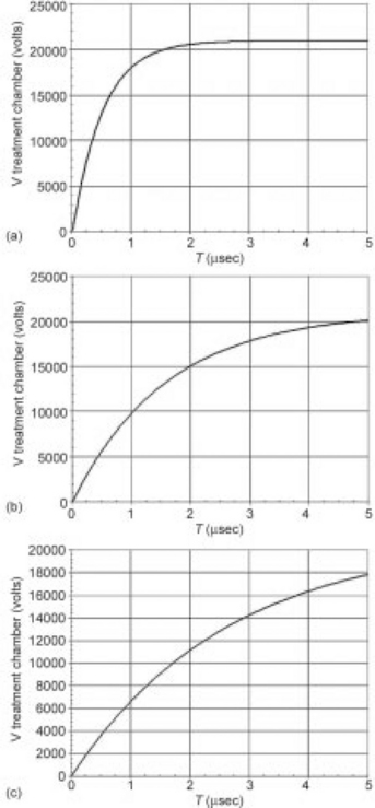
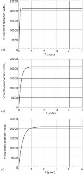
Fig. 4.9 Modeled pulse waveforms for 6:1 transformer coupled (a–c) and hard switch (d–f) modulator designs. Pulse performance into conductivities of 1 mS/cm (a and d), 3 mS/cm (b and e), and 5 mS/cm (c and f) are shown. The variation in risetime of the hard switch modulators due to the changes in load impedance are relatively small, and result in reasonable PEF pulses, with risetimes at or below 1 μs. The transformer coupled system, on the other hand, essentially multiplies the changes in load impedance by the transformer ratio squared (or 36 in this example). The result is that the pulse risetime may exceed total pulse width, preventing the full voltage from being applied.
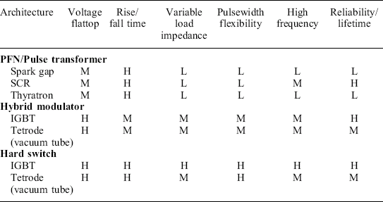
As the pulse-shapes at differing conductivities clearly show, changing the conductivity, significantly changes the pulse waveform. At 1 mS/cm, the pulse is reasonable, but by 5 mS/cm, it may never be possible to get to full voltage within a single pulse before the onset of arcing. A hard switch (lower three pulses), on the other hand, shows much less variation, and maintains a reasonable pulse shape across the range of conductivities, even though the switch performance (risetime, etc.) is the same in both cases. This pulse variability, unfortunately, often eliminates impedance matched modulator designs (using pulse transformers and/or pulse forming networks) from consistent performance in a PEF system. Table 4.4 summarizes many of these key architecture and performance relationships. This is intended to highlight the relative performance differences between each type of architecture, rather than serve as an exhaustive comparison.
4.3.3 Treatment chambers
The third major element of a PEF system is the treatment chamber (Fig. 4.10) where the high voltage pulses are applied to the food. The key attributes of the treatment chamber are its ability to minimally impact the fluid flow, while ensuring a consistent electric field is applied to all elements of the flow. Unfortunately, these two attributes are often in conflict, making design of the treatment chamber a critical exercise in system optimization.
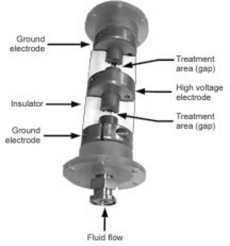
Fig. 4.10 Cutaway view of OSU co-field flow chamber built under license by DTI. The food flows through the small hole in the center of the chamber diameter, and the high voltage pulses are applied to the center conductor, establishing two treatment areas within the chamber itself.
It is critical that the treatment chamber design produce a consistent field over the gap, and be as immune as possible to arcing (electrical breakdown). The two basic factors affecting treatment chamber design and operation are the physical configuration of the chamber, and the electrode and insulator materials themselves. There are many chamber designs that have been developed and patented over the last 20 years, but the prevailing approach is the co-field flow chamber design, developed and patented by OSU. This design has been shown to provide the optimal balance between the flow and field requirements. One critical attribute of this design, however, is that to maintain consistent field strengths, the gap over which the field is applied must be proportional to the pipe diameter. Therefore, larger pipe diameters, which support higher flow rates, require proportionally higher pulse voltages to maintain the same field strength. The co-field flow design is best utilized at 5 cm pipe diameters and below, which translates to ~ 200 kV pulses (at 40 kV/cm), the nominal limit for solid-state, hard switched modulators. For larger pipe diameters, alternative modulator or treatment chamber designs are likely to be required.
In most PEF systems, the voltage is applied to the fluid across multiple treatment chambers, which are used in (fluid flow) series as the fluid passes through the PEF system. This allows the desired treatment time to be applied to a faster flow rate, at lower pulse frequencies, and helps ensure that every element of the flow receives the desired field strength and duration, for more consistent treatment. All of the PEF treatment chambers have two primary elements: the electrodes, which are conductors that pass the electrical voltage into the liquid being processed, and the insulators between these electrodes, which maintain the ‘gap’ between electrodes, where the voltage field is applied (Fig. 4.11).
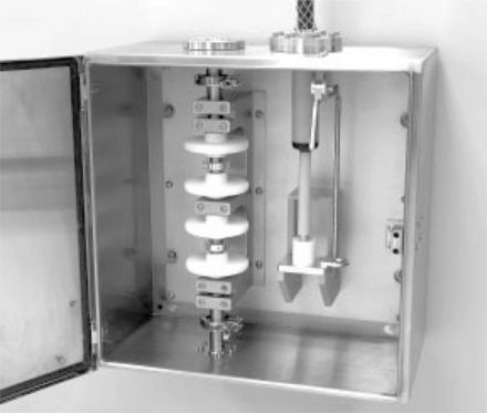
Fig. 4.11 Commercial-scale treatment chambers, at 1 cm diameter and 1.25 cm gap. Two chambers, with four treatment zones, are included in this design. The insulators are the four white discs, with the HV connections between the top two and bottom two insulators. Quick disconnects allow rapid assembly and disassembly of the treatment chambers for cleaning and electrode replacement.
Insulators are the simplest aspect of this design. Substantial research has been conducted in the high voltage world, for radar, power distribution, and other applications, to characterize insulator capabilities and failure mechanisms. Multiple insulators exist from this known population that are food-grade materials, allowing their use in PEF treatment chambers. The key is to utilize a material which can withstand both the electrical stresses within the treatment chamber as well as the mechanical stresses imposed by rapidly pulsing the electrodes (due to the electromagnetic force applied during each pulse).
Electrodes, on the other hand, are still an active area of research. Early PEF electrodes were built from carbon (graphite), with the intent of avoiding any contamination of the treated product by non-food materials. Unfortunately, these early electrodes had very short lifetimes. The electrical current would erode them rapidly, and deposits would develop on the electrode surfaces, which acted as electrical insulators. These early studies reported electrode life ranging from tens to hundreds of hours. When an electrode needs to be replaced, the cost incurred is not only the cost of the electrode, but also the cost of the system downtime for the electrode replacement and the cost of cleaning the entire process line before operation can be resumed. Since those early PEF systems in the 1980s, considerable research has been performed to develop treatment chambers with extended operational lifetimes, supporting extended, continuous operation of the PEF systems in both R&D and commercial applications.
There are three major factors that impact electrode life: erosion, cathodization, and deposition. Erosion relates to physical wear of the electrode as the fluid passes through it. Many foods, especially those that are acidic or highly particulate, will cause electrode erosion even in the absence of high voltage pulses. This is not a significant problem, or it would be experienced in every liquid processing system, including pasteurization systems. More critically, the application of high voltage pulses leads to cathodization of the negative electrode, where electrode ions are transported out of the electrode by the voltage itself. Minimizing this effect, while maintaining food safety, is therefore a major area of research. Figure 4.12 shows the relative cathodization of different materials in OSU’s experiments, and shows that titanium (Ti) and platinum (Pt) have the best performance. The key is that minuscule amounts of material are introduced into large volumes of fluid, and these very low concentrations are acceptable in every known country, allowing use of these materials in PEF system. DTI and others have worked with a variety of materials, including combinations of materials, in electrodes with excellent results to date.
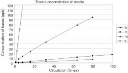
Fig. 4.12 OSU data showing the erosion levels of PEF treatment chamber electrodes (Ti = titanium; Pt = platinum, Fe = iron, B = boron) in re-circulated media. Higher concentrations show that more electrode material has been transferred into the media. Note that for typical PEF applications, the food passes through the treatment chambers only once.
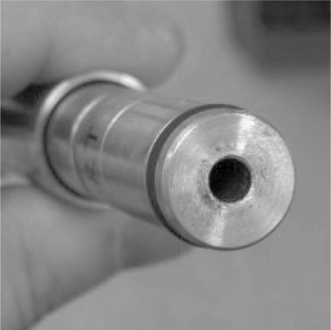
Wear on the electrode is also caused by arcing and corona discharge within the electrode. This is not a normal product of PEF processing. It occurs when the voltage is not well controlled, or when dissimilar particulates within the fluid cause areas of field stress beyond the breakdown voltage of the liquid. DTI’s solid-state, high voltage systems are specifically designed to maintain voltage control within the system. They identify and respond to arcing very quickly by removing voltage from the chambers, limiting arc energy and the pitting at the arc site on the electrode (Fig. 4.13). This capability alone appears to minimize the effect of arcing on the electrode, as demonstrated in multiple DTI systems.
Another potential cause of electrode wear has been reported in the literature as a result of DC or low frequency currents – primarily leakage currents between high voltage pulses. Every solid-state high voltage switch has some leakage current when the switch is off ranging from micro-amps to milliamps. Based on this data, preventing this wear requires that the leakage current must be prevented from flowing through the treatment chambers themselves. In PEF systems with pulse transformers, and in bi-polar systems, this leakage current is shunted around the treatment chambers, and therefore has no impact. For hard switched, mono-polar systems, it is possible to include a bypass inductor in parallel with the treatment chamber. This inductor appears as a short circuit between high voltage pulses (which will waste energy), and as an open circuit during the short PEF pulses. At the same time, however, the erosion of the electrodes is almost exclusively related to the total amount of charge flowing through them. In a commercial PEF system, however, operating at hundreds of amps of peak current, it would take decades of leakage current to equal the charge transport represented by one hour of pulsed operation.
The final factor related to treatment chamber design and lifetime is anodization/deposition of material on the positive electrode. This is the major argument for bi-polar pulsing: alternating the polarity of the pulses applied in the treatment chamber may prevent molecules from depositing on the positive electrode (since it becomes the negative electrode in the next pulse). There are two sources of potential deposition on the electrode, the cathode and the liquid itself. It is difficult to envision that true anodization can be an issue in a PEF system, since the liquid flow in the chamber will transport any ions from the cathode out of the chamber before they deposit on the anode. Since PEF is a single pass system, there is little opportunity for these ions to reattach. A more likely effect is that proteins and other ionized molecules within the liquid deposit on the electrodes, especially in areas of high field strength. The anecdotal evidence for this is widespread, but is primarily associated with electrodes with very rough surfaces (such as the graphite electrodes used in early PEF systems). Again, recent data shows that operating with shorter pulses at higher pulse frequencies minimizes this effect. There are, however, still issues to be addressed with specific products (such as milk), which seem to create deposits on the electrodes relatively rapidly.
4.4 Pulsed electric field (PEF) system trade-offs and optimization
As the previous sections have demonstrated, there are many factors that impact the design of a PEF system. There are technical constraints on all levels of the equipment, operational requirements that must be met, and financial criteria that must be achieved to make PEF processing a profitable endeavor. Balancing these competing criteria is key to the optimization of PEF systems for commercial processes. Our approach is to begin with the fixed parameters facing every PEF system. All of the key PEF system design parameters trace back to the following three elements:
![]() required process protocol (field strength, treatment time)
required process protocol (field strength, treatment time)
The critical, and often least defined, parameters come from the treatment protocol itself. A starting point for these conditions can typically be found in the PEF research literature, but often requires specific experimentation to define the specific process conditions required. As discussed earlier, it is critical that the pulse shapes in the pilot system are as similar as possible to those of the commercial system to allow the results to be readily scaled. These parameters alone allow calculation of the average power required in the PEF system, which determines the overall system size. The system voltage and treatment chamber size (which are directly related) are the first parameters to be selected. A 35 kV/cm field strength requirement, for example, can be satisfied by a 35 kV pulse power system, with a 1 cm gap distance, or a 17.5 kV system with 0.5 cm gaps, or any other combination which results in the desired field strength. The treatment chamber size, in turn, dictates both the current required in each chamber for each pulse (due to the chamber volume and fluid conductivity), and the chamber diameter (which, with viscosity, determines the pressure drop in each treatment chamber). Finally, the number of chambers, pulsewidth, and pulse frequency can be adjusted to ensure that the fluid receives the desired total treatment time.
All of these parameters are interactive, and must be simultaneously assessed against the cost and complexity (and often, even the feasibility) of the required pulse modulator. At DTI, we perform these optimizations regularly, and have developed software tools to support these interactive design decisions. They are not, however, generalizable. They are based on our approach to pulse modulator design, and other modulator designs would lead to different optimizations.
Three potential system designs are illustrated in Table 4.5 for the same protocol and conductivity, based on the requirement for processing 5000 liters/hour of juice (conductivity 5 ms/cm) at 35 kV/cm for 40 μs total treatment time. Each column represents a different approach to the PEF system design, with the major variable being the number of treatment chambers used (1–4). The only common parameter is average power, which is wholly dependent on the desired treatment time and field strength. The Delta T/chamber, multiplied by the number of chambers, is a constant, so the protocol determines the total temperature rise. With multiple chambers, the temperature rise is lower in each chamber, introducing the opportunity to minimize temperature excursions by cooling the product between treatment chambers. This is not possible in the single chamber design.
Table 4.5
PEF system sizing examples, with differing numbers of treatment chambers Protocol was 35 kV/cm, 40 μs treatment time, with a conductivity of 5 ms/cm. Pressure was not considered in developing these examples
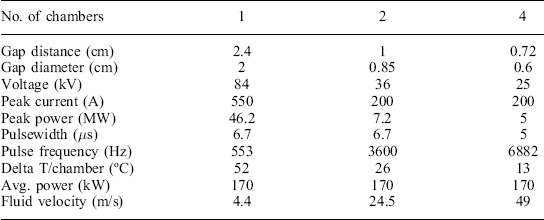
The peak power required from the modulator decreases considerably as the gap distance is reduced (and more chambers are added). For solid-state modulators, the major determinant of cost is typically the peak power required, which is clearly lowest in the four chamber design. The selection of a specific design for this set of conditions, however, may hinge on two major factors: the ability of the modulator to operate at the higher pulse frequency, and the pump pressure required to maintain the fluid velocity through the four chambers. Operating at high pulse frequencies increases the switching losses in the modulator proportionately, and can create thermal problems in the switches if not carefully designed and cooled. Pump pressure (not shown, but calculable from the fluid velocity and viscosity, number of chambers, and chamber diameter) is typically limited for a commercial system, as it affects not just the pumps, but fittings, pipes, and other components, including the treatment chambers themselves. Optimization of a PEF system for any given application clearly requires a close interaction between the design of the pulse power system, and the capabilities of the rest of the plant in terms of pumping, cooling, etc.
The final factor in system optimization cost is often the most critical. For commercial systems, the cost that matters is made up of two elements: the capital cost for a level of capacity (in $/liter/hour), and the cost of the electricity needed to provide the PEF treatment itself. The electricity cost is made up of two parts: the protocol (which is typically not subject to change), and the efficiency of the PEF system itself. As described earlier, the closer the pulse shape of the PEF system is to the ideal pulse (zero rise and fall-time, perfect stationary flattop), the higher the system efficiency. For a commercial system, operating nearly continuously, improvements in system efficiency (even at the expense of higher initial system costs) typically yield the lowest overall processing cost.
Finally, PEF system capacity directly affects the capital cost (on a per-liter basis). Moving to higher capacity means increasing the pulse voltage and average current in the system, which directly translates to higher PEF hardware costs. These costs do not increase linearly with the added capacity – so the overall per-liter cost goes down, making larger systems more economical than pilot systems on that basis. As an example, the commercial PEF system shown in Fig. 4.14 has a process capacity over 10 × the product per hour as the pilot system shown in Fig. 4.16, but costs only 5 × as much, which is half the cost in $/liters/hour. Beyond a certain size, however, the sheer scale of the equipment (in terms of voltage and average power) begins to make this cost increase faster than the additional capacity. At that point, it makes more sense to increase plant capacity by duplicating smaller systems, rather than building ever larger systems. DTI’s current assessment is that this crossover point is reached around 500 kW of average power, but this size is increasing over time, as PEF (and other pulsed power system) designs mature.
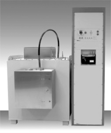
Fig. 4.14 Commercial-scale PEF system, rated at up to 300 kW average power. The modulator and treatment chambers are shown. One 150 kW power supply used with this system is shown in Fig. 4.4. This system can treat up to 10 000 liters/hour.
4.5 Pulsed electric field (PEF) processing and commercialization status
PEF processing has been the subject of focused R&D for over 20 years. In its earliest days, the emphasis was on validating and defining the ability of high voltage pulses to kill bacteria, molds, and other potential pathogens. In the early 2000s, programs in both the US and Europe focused on scaling the results discovered in the laboratory to commercially viable processes and systems. Since that time, several key developments have brought PEF processing to the brink of wide-scale commercial adoption. First, Genesis Juice Corporation introduced the first FDA approved, PEF processed juices to the US market in August, 2005 (Fig. 4.15). Genesis Juice Company was formed in 1977 to produce and sell organic, unpasteurized fruit juices in the Portland, OR market. As a result of a 2001 change in FDA policy concerning ‘unpasteurized’ juices, Genesis received a ‘warning letter’ of non-compliance from the US Food and Drug Administration on 13 November 2003. Genesis customers removed the company’s products from their shelves by February, 2004. Genesis undertook a search for alternatives to pasteurization, which led the company to PEF processing. PEF processing offered the promise of retaining the fresh flavor and nutrients at the heart of Genesis’ products, while allowing the company to meet the new FDA regulations. In April 2004, Genesis reached an agreement with OSU to conduct a cooperative research effort on Genesis’ juices using PEF processing. By August, 2005, Genesis had met the FDA’s requirements using PEF processing, and was able to re-enter the juice market with a line of PEF processed juices, thereby representing the first FDA approved use of PEF for safe, wholesome commercial food products in the US. Consumer acceptance was very high, and Genesis attempted to expand its market reach in the Pacific Northwest, supported in part by the extended shelf life of PEF processed juice, which conferred additional time for shipment and distribution beyond Genesis’ traditional, local markets.

Unfortunately, the financial impact of no sales for over 18 months, combined with the capital requirements of rapid growth, proved fatal to Genesis. The company was forced to cease operation before selling its brand name in mid 2007. At the time, however, market acceptance of PEF processed juice was strong and growing. At approximately the same time, DTI introduced a standard pilot-scale PEF system (Fig. 4.16), capable of treating 100–500 liters/hour of juices or other products, allowing researchers to process a variety of products for both R&D and pre-production process definition. Since that time, these pilot systems have been deployed to research facilities around the world, including the US, Europe, and Australia. As a result, Genesis and DTI were awarded the Institute of Food Technologists’ Food Technology Industrial Achievement Award in 2007. Finally, the world’s first known commercial deployment of large-scale PEF technology occurred in 2006 (Fig. 4.14) in Mesa, Arizona. This system, rated at 10 000 liters/hour capacity, was deployed for wastewater treatment, rather than food processing, but contains all of the same system elements. In over 30 months of operation to date, this system has demonstrated the ability to meet the same operational concerns that would impact a food processing plant – efficiency, reliability, electrode life, and unattended operation. There are at least three companies, including DTI, building PEF systems, at both the pilot and commercial scale, so commercial PEF systems are now readily available to food processors.
4.6 Conclusions
Multiple researchers have shown PEF processing to be equivalent to pasteurization in terms of pathogen reduction for a wide range of liquid foods.
For foods that are heat sensitive, there are considerable benefits in taste, color, and nutritional value from the non-thermal PEF process. The application of PEF to other industrial processes builds directly on the research in food processing, and new applications of PEF are emerging at a significant pace.
The use of solid-state, high voltage pulsed power systems for PEF processing is the key to these commercial applications. Solid-state technology allows this PEF to scale from small laboratory systems to large-scale processing facilities.
There are three identified areas where further system development is required. The first is achieving common definitions for critical PEF parameters, such as field strength, pulsewidth, and treatment time. While the definition of these parameters may seem trivial, the ambiguities in their application prevent both researchers and commercial operators from developing an accepted and available set of treatment protocols for differing foods. Developing common definitions and processes for PEF protocols and systems will help researchers, system developers, regulators, and food processors to clearly communicate their needs and constraints, and allow all sides to achieve their objectives more economically.
Second, while there has been considerable research into treatment chamber designs and materials, the PEF community has limited experience with extended, commercial operations. Genesis Juice, and DTI’s experience in wastewater processing, demonstrate that it is possible to build robust, long-lasting treatment chambers, but we do not have an ideal solution. Considerable work remains to fully optimize these treatment chamber designs, especially for high protein foods.
Finally, the overall design of the pulsed power systems for PEF is maturing. New pulse power technologies are allowing PEF systems to become smaller and less expensive. The entire community is gaining experience in specifying, building, and operating PEF systems. Commercial PEF processing is now a viable alternative to pasteurization for a number of heat-sensitive products.
4.7 Bibliography
Barbosa-Canovas, G., Gould, G. Innovations in Food Processing. Technomic; 2000.
Barbosa-Canovas, G., Zhang, Q.H. Pulsed Electric Fields in Food Processing. Technomic; 2001.
Barbosa-Canovas, G., Zhang, Q.H. Pulsed Electric Fields in Food Processing. C.H.I.P.S; 2002.
Barbosa-Canovas, G., Gongora-Nieto, M., Pothakamury, U., Swanson, B. Preservation of Foods with Pulsed Electric Fields. Academic Press; 1999.
Barbosa-Canovas, G., Tapia, M., Cano, M. Novel Food Processing Technologies. C.H.I.P.S; 2004.
Clark, J.Pulsed electric field processing. Food Technology, 2006. [Jan., pp. 66–67].
Dunn, J.E., Pearlman, J.S. Methods And Apparatus For Extending The Shelf Life Of Fluid Food Products, 1987. [Us Patent 4,695,472].
Gaudreau, M., Hawkey, T., Kempkes, M., Petry, J., Zhang, Q.H., A Solid-state Pulsed Power System for Food Processing. International Food Technology Conference, 2001.
Gaudreau, M., Hawkey, T., Petry, J., Kempkes, M., Design Considerations for Pulsed Electric Field Processing. Proceedings of the European Pulsed Power Conference, 2004.
Gaudreau, M., Hawkey, T., Petry, J., Kempkes, M. Scaleup of Pef Systems for Food and Waste Streams. 3rd Innovative Food Centre Conference, 2006.
Jeyamkondan, S., Jayas, D.S., Holley, R.A. Pulsed electric field processing of foods. J. FoodProt.. 1999; 62(9):1088–1096.
Kempkes, M., Casey, J., Gaudreau, M., Hawkey, T., Roth, I., Solid-State Modulators for Commercial Pulsed Power Systems. Pulsed Power Conference, 2002.
Li, S.Q., Zhang, Q.H., Electrode Erosion Under High Intensity Pulsed Electric Fields. Proceedings of the International Food Technology Conference, 2005.
Min, S., Jin, T., Zhang, Q.H. Commercial scale pulsed electric field processing of tomato juice. J. Agric. Food Chem.. 2003; 51(11):33383344.
Morren, J., Roodenburg, B., De Haan, S.W.H. Electrochemical reactions and electrode corrosion in pulsed electric field (PEF) treatment chambers. Innovative Food Science and Emerging Technologies. 2003; 4:285–295.
Raso, J., Heinz, V. Pulsed Electric Fields Technology for the Food Industry. Springer; 2006.
Salengke, S.K., Zhang, Q.H. Modeling of Pulsed Electric Field (Pef) Processes. Proceedings of the International Food Technology Conference, 2002.
Toepfl, S.Pulsed Electric Field (Pef) for Permeabilization of Cell Membranes in Food and Bioprocessing – Applications, Process and Equipment Design and Cost Analysis, PhD Thesis. Technical University of Berlin, 2006.
Usda Center For Food Safety And Applied Nutrition, Kinetics of Microbial Inactivation for Alternative Food Processing Technologies: Pulsed Electric Fields, 2000. [2 June].
Yeom, H.W., Streaker, C.B., Zhang, Q.H., Min, D.B. Effects of Pulsed Electric Fields on the Activities of Microorganisms and Pectin Methyl Esterase in Orange Juice. Ohio State University; 2000.
Yin, Y., Zhang, Q.H., Sastry, S.K. High voltage pulsed electric field treatment chambers for the preservation of liquid food products, 1997. [US Patent 5,690,978].