
Structural integrity of polymer matrix composite panels in fire
Abstract:
Developments in advanced composite technology offer cost-effective application of polymer matrix composites for large load-bearing structures. However, polymer matrix composites can be severely damaged under thermal conditions caused by fire. This chapter addresses failures of polymer matrix composite panels under combined thermal-mechanical conditions. Specifically, the thermal load is fire exposure which can occur in accidental events, and the mechanical load is in-plane compression which is the common loading condition for panels in naval structures and civil infrastructure. The failure modes under such thermal-mechanical conditions for single-skin and sandwich panels are the focus in this chapter. The thermal field under fire heating and the degradation of mechanical properties with respect to temperature rise are discussed. Modeling methodology for these failure modes is presented. The development of a quantitative approach to assess structural fire integrity is discussed in the context of analysis and experimental observation.
4.1 Introduction
Developments in advanced composite technology offer cost-effective application of polymer matrix composites (FRPs) for large load-bearing structures. In addition to cost effectiveness, these composites are designers’ materials that can be designed to have specific high strength and high stiffness, high fatigue resistance, and high corrosion resistance, for specific needs. One of the major concerns associated with the acceptability of the composite constructions, e.g. ship construction, is fire performance. Fire performance includes both flammability and structural characteristics. Flammability includes the consideration of heat release, flame spread, toxicity, and smoke production. Structural issues include the ability of the composite structures to carry internal and external loads before, during, and after fire.
The objective of the framework for structural fire integrity of polymer matrix composites is to establish a fundamentally sound basis upon which the design criteria of the composites can be developed, and accordingly, the design and operation practice of the composite structures can be performed safely. The goals are: (1) to develop and demonstrate the ability of new composite systems to display high levels of structural integrity when subject to severe fire exposure; (2) to develop and demonstrate the capability to predict and design vis-à-vis combustibility, flame spread, smoke generation, toxicity, and the structural responses to thermal-mechanical loads. As an example of the current status of using these composites, the US ship regulations defined in the Code of Federal Regulations and the international ship regulations defined by the International Maritime Organization (IMO) through the International Convention for the Safety of Life at Sea (SOLAS) have strict restrictions for the use of combustible materials in construction. The International Code of Safety for High-Speed Craft (HSC, 1995) allows the use of combustible constructions, but requires the vessels to meet very strict operation, management and evacuation requirements.
The behavior of polymer matrix composites with combined thermal-mechanical loads is different from that with only mechanical loads. A significant decrease in mechanical properties such as Young’s modulus and failure stress, known as thermal softening, is observed when the temperature rises to 100 °C from room temperature. Hence, the composites significantly lose load-bearing capacity with modest temperature rise. When heated to a higher temperature range (about 300 °C), where chemical decomposition of polymers occurs, the associated phase transition creates char materials which are significantly different in thermal and mechanical properties from virgin materials. In the phase transition, heat generation, the loss of mass, and the variation of thermal properties are influenced by the rate of the decomposition whose effects need to be accounted for in the thermal model. The thermal process introduces various heterogeneous microstructures, such as gas-filled pores, matrix cracking, and matrix-fiber debonding, which can have significant roles in the composites’ macroscopic deformation. Non-uniform temperature field, i.e. thermal gradients, in polymer matrix composites is another aspect that is different from the conventional materials, such as aluminum alloys, which has reasonably assumed isothermal condition and therefore relative simplicity of failure modes via uniform degradation in stiffness and strength. Polymer matrix composites possess much lower thermal conductivities such that they develop thermal gradients and thereby strong gradients in stiffness, strength and other physical properties. The analysis of failure modes and the base for setting allowable limits for thermal loading are, accordingly, more difficult. The deformations and thus mechanical failures are more varied and complex, e.g. even without mechanical loads, thermal expansion induced by the non-uniform temperature field causes non-uniform deformation field. Therefore, investigation of these composites in the thermal-mechanical condition requires the theory of non-homogeneous materials.
The attention of this chapter is confined to structural behavior and load-bearing capacity of the composite panels in fire. Such plate type or shell type structures are common in ship structures, e.g. hull, bulkhead and decks, and in civil infrastructures. Our focus is on analytical modeling projects carried out at the structural engineering department of the University of California at San Diego (UCSD), based on the experimental performance and observations aimed at understanding the structural response in the combined thermal-mechanical environment. Some of the discussion is based on our unpublished work and the extension of our published work.
The chapter builds on the contribution of many researchers, including those at other institutions; some concentrate on structural response while others on material behavior. Broadly speaking, the thermal model discussed in Section 4.2 originates from that developed by Henderson et al., (1985) for considering phase transition in the chemical decomposition of polymers. The power-form degradation model discussed in Section 4.3 was built from that suggested in the book by Hollaway and Head (2001). The buckling load and skin wrinkling load obtained in Sections 4.4 and 4.5 for non-homogeneous sandwich material systems are the development of Allen’s solutions for homogeneous sandwich material systems (Allen, 1969). The micromechanical approach of crystal plasticity (Asaro, 1983) to simulate interlaminar shearing and debonding in Section 4.6 is the latest effort to bridge the gap in investigations between material behavior at the microstructure/specimen level and structural response at the component/system level. In addition, a group of researchers at Royal Melbourne Institute of Technology (RMIT) and the University of Newcastle-upon-Tyne has carried out a set of detailed modeling and experimental work on the material behavior of composite laminates in fire (Mouritz et al., 2009).
4.2 Temperature distribution
When polymers are heated to sufficient high temperature, say about 300 °C, phase transition occurs during chemical decomposition (pyrolysis) to create char materials and gases. The original thermal model to account for such phase transition was developed by Henderson et al. (1985). The model assumes that the produced gases flow in the space, and no solids or solid particles flow in the space. For uniform heat flux in Fig. 4.1, the heat transfer model is one-dimensional along the y direction. The energy conservation leads to the following equation:
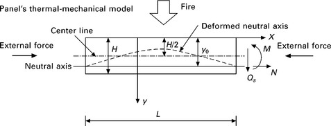
4.1 A thermal-mechanical model for composite panels: combined one-sided fire exposure and in-plane compressive load. Right side shows positive signs of internal forces on cross-section.
where ρ is the mass density of the composite; k is the thermal conductivity of the composite; ![]() is the mass flux of the gas; hg is the enthalpy of the gas; Q is the heat of decomposition; Cρ = ∂h/∂T is the specific heat of the composite, where h is the enthalpy of the composite; Cρg = ∂hg/∂T is the specific heat of gas; and T = T(y, t) is temperature, where t is heating time. If the last two terms on the right side are removed, it is the conventional heat conduction equation. The last two terms on the right side represent the energy change rate due to the flow of the gas and the heat generation. The thermal conductivity varies along the thickness due to its degradation at elevated temperature.
is the mass flux of the gas; hg is the enthalpy of the gas; Q is the heat of decomposition; Cρ = ∂h/∂T is the specific heat of the composite, where h is the enthalpy of the composite; Cρg = ∂hg/∂T is the specific heat of gas; and T = T(y, t) is temperature, where t is heating time. If the last two terms on the right side are removed, it is the conventional heat conduction equation. The last two terms on the right side represent the energy change rate due to the flow of the gas and the heat generation. The thermal conductivity varies along the thickness due to its degradation at elevated temperature.
Since there is no accumulation of decomposition gas in the solid material, the conservation of mass is written as:
To describe the rate of mass density change, the Arrhenius equation is introduced:
where A is a pre-exponential factor; Ea is activation energy; R is the universal gas constant; n is the order of reaction; ρv is the mass density of virgin material; and ρc is the mass density of char material. The material constants in [4.3], A, n and Ea, are obtained by fitting experimental data, usually the TGA (thermal gravimetric analysis) data which measure the mass loss as the function of temperature for controlled heating rates.
The evolution of the thermal conductivity and specific heat of the composite during the reaction is governed by the mixture rule:
where kv and kc are the thermal conductivities of virgin material and char material, respectively; and Cρv and Cρc are the specific heats of virgin material and char material, respectively. In general, these thermal conductivities and specific heats of virgin and char materials, as well as the specific heat of gas, are temperature dependent (Henderson et al., 1885; Lattimer and Ouellette, 2006; Lua et al., 2006). The mixture factor F is the ratio of the current mass density and the original mass density, namely F = (ρ – ρc)/(ρv – ρc).
The governing equation [4.1] can be solved along with the supporting equations [4.2–4.4] and thermal boundary conditions, given the material constants, A, n, Ea, kv, kc, Cρv, Cρc, Cρg, Q, ρv, and ρc. The boundary condition at the exposed face is generally convective and radiative exchange with surroundings and can be stated as:
where q0 is the radiative heat flux; hconv is the heat transfer coefficient; σ is the Stefan-Boltzmann constant; Tr is ambient temperature; and εr and εm are the emissivity of the surroundings and the composite surface, respectively. If the boundary condition is temperature versus time curve at the exposed face we have:
The thermal boundary condition at the unexposed face is similar. If the unexposed face is insulated, ∂T(H, t)/∂y = 0. The mass flux of gas satisfies ![]() . The initial condition is T(y, 0) = Tr; ρ(y, 0) = ρv;
. The initial condition is T(y, 0) = Tr; ρ(y, 0) = ρv;![]() .
.
The solution to the thermal model can be written into dimensionless form. From the expression [4.3], the mass density takes the following non-dimensional form:
The function fρ is non-dimensional. Using [4.4] and [4.7], we get the non-dimensional forms of the thermal conductivity and specific heat:
The non-dimensional form for the temperature field is obtained by substituting [4.7] and [4.8] into [4.1] and regrouping the physical parameters. This leads to:
where β = κv/ρv/Cρv, and Ψ represents the thermal boundary conditions. For the specified curves of temperature versus time at the exposed and unexposed faces, Ψ = (Tf/Tr, Tb/Tr), where Tb is the temperature of the unexposed face. For insulated unexposed face, the last argument Tb/Tr is removed. If the exposed face is specified by a heat flux q, the argument Tf/Tr is replaced by qH/(Trkv). The non-dimensional form [4.9] helps us to characterize the contribution of each physical parameter to the temperature profile.
The thermal model can be solved numerically using finite difference finite element methods. Past research for the thermal model includes verification with experiments, investigation of composites’ thermal properties, and efficient numerical schemes. Henderson et al. (1985), Henderson and Wiecek (1987) and Wu et al. (1993) employed the finite difference schemes for the thermal model; Looyeh et al. (1997), Looyeh and Bettess (1998) and Krysl et al. (2004) described finite element schemes. Gibson et al. (1995) employed the thermal model to study failure mechanisms for specimens in one-sided fire exposure. In Dodds et al. (2000), various calculated results were verified by measured data from fire testing. Instead of the Arrhenius equation [4.3], Trelles and Lattimer (2007) and Asaro et al. (2009a) used the variation of mass density with respect to temperature at a single heating rate to represent the rate of decomposition in the thermal model. In Feih et al. (2007a, 2007b, 2010), various incident heat fluxes were tested, and it was found that in general the calculated results were in good agreement with experimental results (see Fig. 4.2). The exception was the case of high heat flux intensity where the composite ignited after some heating time. The ignition of the composites, which is not considered in the thermal model, results in higher temperature and increases the rate of decomposition. In Asaro et al. (2009a), the thermal model was used to evaluate and characterize the thermal-physical performance of fire protective coatings for naval ship structures. However, in certain cases, the solution of the thermal model was shown to be sensitive to the parameters characterizing phase transition, e.g., the small change in the mass density of the char can result in significant change in the temperature field (see Fig. 5 in Krysl et al., 2004). In addition, there are limited sources for these material property data describing the phase transition beyond the mentioned publications.
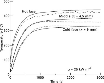
4.2 Temperature–time response of the laminate at a heat flux of 25 kW/m2. The measured and calculated temperatures are shown by the dashed and solid lines, respectively. From Feih et al. (2007a). Used with permission from Elsevier.
At temperatures below chemical decomposition, the terms and parameters for the decomposition can be removed from [4.1] so that the heat transfer equation becomes:
The thermal material properties in the virgin state may be taken as temperature independent (Asaro et al., 2009a). The non-dimensional form for the temperature field [4.9] becomes:
When the temperature field is obtained from [4.1] or [4.10], the structural analysis can be performed to determine mechanical load-bearing capacity.
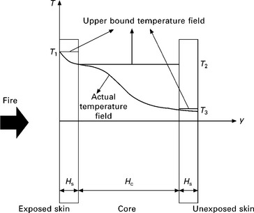
In Dao and Asaro (1999) and Asaro et al. (1999), numerical solutions of the temperature field were obtained for representative panels made of E-glassl vinylester composites by solving the thermal model using the measured temperatures at the exposed and unexposed faces. Based on these solutions, simplified temperature distributions were discussed. The simplified temperature distributions capture the major features of the actual temperature variations using the temperature values measured at the key locations in thermal tests. For single skin panels, a two parameter model was proposed, which used two of the key temperature values, i.e. those at the exposed face, the center, and the unexposed face, to construct a linear temperature distribution. For the simplified temperature distribution of sandwich panels, the temperature at the unexposed skin can be taken as ambient temperature because the low conductivities give rise to small temperature change of the unexposed skin for a considerable period of heating time. Figure 4.3 systematically shows the piecewise step temperature distribution, i.e. simplified temperature distribution, derived from the actual temperature field. The three key temperature values that characterize the simplified distribution are the temperature at the exposed face, the temperature at the interface between the exposed skin and the core, and ambient temperature at the unexposed skin. The simplified temperature distribution is also called the upper bound temperature field because the above key temperature values are the maximum temperatures in the skins and the core.
4.3 Material behavior at elevated temperature
The degradation of the Young’s modulus with respect to temperature, T, may be given by the power form:
In [4.12], which is systemically shown in Fig. 4.4, E0 is the Young’s modulus at ambient temperature Tr, or initial stiffness. The power index m varies from 0 to 1, with m = 0 being no degradation before the temperature reaches the reference temperature Tref. As shown in Fig. 4.4, the reference temperature characterizes the end of the major stiffness degradation which happens in the temperature range T ≤ Tref. The parameter ![]() , which is with a unit of temperature, and the non-dimensional parameter m are obtained from fitting the experimental data in the temperature range T ≤ Tref. In Gu and Asaro (2005), it was suggested that m = 0.2 for E-glass fiber/lvinylester matrix composites. The power law [4.12] is a phenomenological form similar to that suggested in Hollaway and Head (2001, page 97). The ambient temperature Tr is taken as the room temperature 20 °C. Experiments showed that the reference temperature Tref for E-glass fiber/vinylester matrix composites is around 120 °C (Dao and Asaro, 1999).
, which is with a unit of temperature, and the non-dimensional parameter m are obtained from fitting the experimental data in the temperature range T ≤ Tref. In Gu and Asaro (2005), it was suggested that m = 0.2 for E-glass fiber/lvinylester matrix composites. The power law [4.12] is a phenomenological form similar to that suggested in Hollaway and Head (2001, page 97). The ambient temperature Tr is taken as the room temperature 20 °C. Experiments showed that the reference temperature Tref for E-glass fiber/vinylester matrix composites is around 120 °C (Dao and Asaro, 1999).
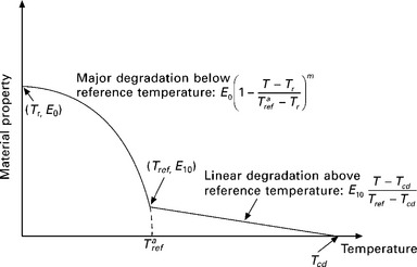
4.4 Power form model of degradation with respect to temperature rise. The model includes one portion below and another above the reference temperature. Above the reference temperature, the degradation is modeled as slow, linear variation with respect to temperature.
In [4.12], E1(T) is stiffness above the reference temperature, which is much smaller than the initial stiffness E0 and reduces to zero at the starting temperature of chemical decomposition Tcd. The stiffness degrades gradually between the reference temperature and the starting temperature of chemical decomposition. For continuity of the stiffness at the reference temperature, we have the following relation from [4.12]:
The degradation law [4.12] is an extension of that discussed in Gu and Asaro (2005) to include the stiffness above the reference temperature. For the case where E1(T) is taken to be zero, we have ![]() from [4.13] such that [4.12] becomes:
from [4.13] such that [4.12] becomes:
Figure 4.5 shows the degradation law [4.14] for several power indexes and some experimental data. The degradation law was used in the analytical simulations of composite panels’ failure modes in Gu and Asaro (2005, 2008a, 2008b, 2008c, 2009) and Gu et al. (2009), where good agreement with experiments was observed.
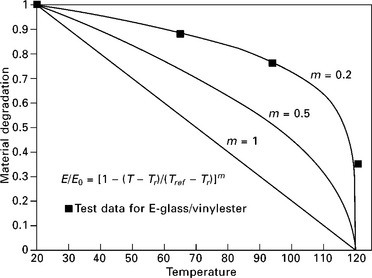
4.5 Simplified power form model of degradation is plotted for several power indexes with some experimental data. From Gu et al. (2009). Used with permission from Elsevier.
A material point in the panel is said to be completely degraded if the temperature at this point is above the reference temperature Tref, since in this situation the material element around this point can no longer take large external loads according to [4.12] or [4.14]. Recent analytical and experimental works (e.g. Asaro and Dao, 1997; Asaro et al., 1999, 2005, 2009b; Birman et al., 2006; Dao and Asaro 1999; Feih et al., 2007a, 2007b, 2010; Gu and Asaro, 2005; Gu et al., 2009; Ramroth et al., 2006) treated thermal softening as well as the phase transition in chemical decomposition as the major influences on the mechanical properties of polymer matrix composites under fire damage. In the analytical simulation using the rate-dependent micromechanical constitutive model (Ramroth et al., 2006) and the experimental evaluation (Asaro et al., 1999; Dao and Asaro 1999), it was found that rate dependence and plastic deformation were unlikely to be the mechanisms for failure of structure-size panels under considered fire protection time. In Asaro et al. (2009b), by analyzing the thermal gravimetric analysis (TGA) data, it was suggested that the rate dependence may be neglected below the glass transition temperature for the case of modest mechanical load in the considered fire-protection period. It further argued that, in certain cases, the creep influence may even be neglected for elevated temperature up to the point where the chemical decomposition starts. In this article, the constitutive theory describing degradation given in [4.12] or [4.14] is used to discuss structural failure modes such as buckling and skin wrinkling.
Other forms of degradation with respect to temperature were proposed by other researchers. Gibson et al. (2006), Feih et al. (2007a, 2007b, 2007c, 2010) and Mouritz et al. (2009) used a hyperbolic tangent function to describe the temperature dependence of the material strength. Dutta and Hui (2000) related the current elastic modulus to the current temperature as well as the current mass density of the composite. The early model by Springer (1984) related current material properties to the loss of mass density. In Bai et al. (2008), who considered different material states in different temperature ranges, a kinetic theory was employed to model the degradations of stiffness, viscosity, and the coefficient of thermal expansion.
Material variation with position y along the thickness of the panel can be obtained by substituting the temperature field T(y, t) into [4.12] or [4.14]. For simplicity, one approximation approach is to write the material variation as the second order polynomial of y:
Consider the single skin panel of thickness H and denote the moduli at the exposed face (y = 0), the center (y = H/2), and the unexposed face (y = H) as Ef, Ec and Eb, respectively. The coefficients in [4.15] are given by interpolation as
Note that the three moduli in [4.16] are temperature dependent according to [4.12] or [4.14]. The second order polynomial form was used in Asaro and Dao (1997) and Asaro et al. (1999) for analytical modeling. Other forms for material variation with position may also be introduced, e.g. the exponential form (Gu and Asaro, 2008c). These simplified forms allow analytical solutions to be presented in compact forms, as will be seen in later sections.
4.4 Global buckling
For composite plates, experiments showed buckling occurred when heated under the operational loads that were considered to be safe under the design criteria without evaluating fire damage (e.g. Gibson et al., 2004; Dao and Asaro, 1999). The latter reference suggested that global buckling was a fairly common failure mode for panels of structural size. In Gu and Asaro (2005), the buckling load was derived from the non-homogeneous theory of elasticity to account for the material variation along the thickness caused by temperature gradient. For sandwich panels, Allen’s formulation for the additional shear deformation of the core (Allen, 1969) was included. The buckling solution is discussed here.
A beam model, as shown in Fig. 4.1, is considered, where the width of panel in the normal direction of the sheet is taken to be a unit value in the following derivation. Due to the mechanical property gradient induced by the thermal gradient along the thickness, the neutral axis is not located at the center of the cross-section, as shown in Fig. 4.1. We apply the Bernoulli–Euler assumption such that the cross-section remains plane and rotates about the neutral axis during bending deformation. The position of the neutral axis is obtained from equilibrium as:
For simplicity, E[T(y, t)] is denoted by E(y). The bending stiffness for the non-homogeneous material or graded material is:
From the bending formulation, the equilibrium equation is of the same form as that for homogeneous materials except the expression of the bending stiffness. This leads to the buckling load for the non-homogeneous material being of the same form as that for homogeneous materials. For pin support (rollers which allow rotation) at both ends, the buckling load of a single panel is:
where l is the length of the panel. The temperature gradient, via material gradient, reduces the critical load through the reduction of the bending stiffness D. For clamping support (which does not allow translation and rotation) at one end and roller support at another end, the coefficient π2 in the above expression is replaced by 4.492; for clamping support at both ends, the coefficient is replaced by 4π2.
The above expression for the pin-supported panel may be scaled by the buckling load of temperature independent materials so that:
D* is non-dimensional buckling load P*cr. One obtains the buckling load by evaluating the bending stiffness using [4.17] and [4.18]. Dimensional analysis considering the temperature field [4.11] leads to the non-dimensional form of the buckling load:
where Π is the group of non-dimensional parameters characterizing the material degradation discussed in Section 4.3, e.g. m for the power law [4.14].
For a sandwich panel, the low shear stiffness of the core introduces additional shear deformation. The approach to include this effect can be found in Plantema (1966) and Allen (1969). For pin support at both ends, the buckling load of sandwich panels with material property variation induced by the thermal gradient was derived in Gu and Asaro (2005) as:
The expressions for the bending stiffness of the sandwich panel D, bending stiffness of the skins Df, and shear stiffness of the core G were given in Gu and Asaro (2009). For other end conditions, clamping/clamping, roller/clamping, the π2 in [4.23] is replaced by appropriate coefficients such as those in the single skin case. The non-dimensional form of the buckling load for the sandwich panel is:
The subscript c is for the variables of the core, and the subscript s is for the variables of the skin; E0s, E0c and G0c are the Young’s modulus of the skin, the Young’s modulus of the core, and the shear modulus of the core, at ambient temperature, respectively. With [4.21] and [4.24], the buckling solutions are presented in terms of non-dimensional parameters. The non-dimensional representations help us to characterize buckling loads, for both understanding structure behavior and designing components in engineering practice.
The staggered approach can be employed for the thermal-mechanical problem. The temperature field is first obtained from the thermal model in Section 4.2. The obtained temperatures are then substituted into the degradation law in Section 4.3 to find the degraded material properties, which, with geometrical properties, determine the buckling load from [4.19] and [4.22]. It is noted that since in such approach the mechanics solutions are independent of the thermal solutions, these buckling solutions, as well as the skin wrinkling solutions discussed in the next section, are applied to the temperature range with or without chemical decomposition. In Gu and Asaro (2005) and Gu et al. (2009), the predicted buckling loads using [4.19] and [4.22] were compared with the measured data of Asaro et al. (1999) and Dao and Asaro. (1999). The tests were carried out using the UCSD multi-axial fire test apparatus (Asaro and Dao, 1997; Asaro et al., 2009b; Dao and Asaro 1999) designed for the panels to expose one-sided fire while maintaining the flexibility of in-plane and out-of-plane mechanical loads. The material properties and dimensional lengths of the specimens were given in the above references. Figure 4.6 shows buckling loads of a single skin panel at some heating times obtained from actual temperature profiles and the estimated buckling load curve obtained by connecting the discrete points with straight lines. The intersection of the buckling load curve and applied load curve is the failure time, which defines the fire protection time period. From the figure, the estimated failure time with applied in-plane compressive load at 6670 N is around 72 minutes, whereas the actual failure time as measured in tests is 65 minutes. A small out-of-plane load was applied in the test to simulate initial imperfection of the panel. The measured deflection is also plotted in Fig. 4.6, which shows that near the failure the deflection increases dramatically due to instability. For sandwich panels, the estimated buckling load curve is plotted for applied compressive load 17 800 N in Fig. 4.7. Also plotted is the measured deflection for the same panel, which shows that near the failure time, around 33 minutes, the deflection again increases dramatically. For recent tests performed at Hughes Associates, Inc. with the same fire test apparatus, the predicted results were again in agreement with the measured results (Asaro et al., 2009b).
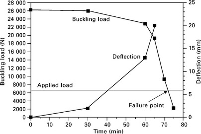
4.6 The computed buckling load vs. heating time for a single-skin panel, where measured out-of-plane deflection and applied load are also plotted. The intersection of the buckling load curve with the applied load curve is the failure point, at which the deflection starts to increase dramatically in a short time period. From Gu et al. (2009). Used with permission from Elsevier.
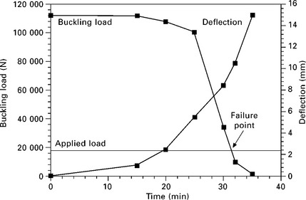
4.7 The computed buckling load vs. heating time for a sandwich panel, where measured out-of-plane deflection and applied load are also plotted. The intersection of the buckling load curve with the applied load curve is the failure point, at which the deflection starts to increase dramatically in a short time period. From Gu et al. (2009). Used with permission from Elsevier.
The investigations of the UCSD group focused on panels of approximately 1 m2 in in-plane size. Mouritz and coworkers (Feih et al., 2007a, 2007b, 2010) studied failures of specimens of approximately 0.1 m2 in in-plane size (effective area of fire exposure). They first determined the variation of the compressive strength with temperature from coupon tests. For composite laminates, with the known temperature field from thermal analysis, the variation of compression strength obtained from coupon tests was integrated through the thickness to obtain the strength of the panel. It appears that no insulation layers were placed at the exposed face in Mouritz and coworkers’ tests. Even though the higher heat flux can result in ignition without insulation at the exposed face, the predicted compressive strength was in good agreement with experimental data. The buckling load was also evaluated using a two-layer model (Gibson et al., 2004), where the fire protection time was shown to be significantly increased by adding constraint at the non-mechanical-loading sides. Laminate theory was employed to treat each ply’s load-bearing capacity individually (Gibson et al., 2006). The work carried out by the groups at UCSD, RMIT and the University of Newcastle showed that the degradation law of mechanical properties with respect to elevated temperature, i.e. those discussed in Section 4.3, can be used to model the deformation behavior of the composites in compression, when overlooking micromechanical behaviors under the fire protection time period. If the panel is subjected to tensile in-plane load during fire, the situation can be different since for the tensile load the deformation mechanism of fiber is different from that of the matrix. In addition to thermal softening, the time-dependence (creep) of the fiber may need to be considered. In Feih et al. (2007c), a degradation model with both time and temperature dependences was proposed for the glass fiber in tension. In addition to in-situ fire behavior, residual fire behavior was investigated, for example by Gibson et al. (2003, 2004), Mouritz and Mathys (1999, 2001), Mouritz (2002, 2003) and Mouritz et al., (2004).
Since the staggered approach treats the thermal analysis and mechanical analysis separately, the non-homogeneous mechanics solutions described in this section and in the following sections, as well as those given in the references, can be used to evaluate the structural behavior in fire and after-fire when the appropriate material degradation law, with respect to temperature and time, is determined.
4.5 Skin wrinkling of sandwich panels
Skin wrinkling is a failure mode of sandwich polymer matrix composite panels under in-plane compression. The low transverse stiffness of the core with relative small skin thickness can make skin wrinkling to be the favored failure mode against buckling. Two analytical approaches to evaluate the wrinkling stress, one based on energy balance and another equilibrium equation, were described in Plantema (1966), Allen (1969), and Zenkert (1995). Recent modeling and experimental wrinkling analyses for various loading conditions and material behaviors include Vonach and Rammerstorfer (2000), Gdoutos et al. (2003), Birman and Bert (2004), Fagerberg and Zenkert (2005), and Kardomateas (2005). However, in the above references, the influence of mechanical property gradients, e.g. those caused by one-sided fire heating or those in functionally graded materials, was not investigated. In Gu and Asaro (2008c), using a constructed Airy stress function for the graded material, the analytical wrinkling load for sandwich system with material gradients was derived for the case in which the core’s thickness was infinitely large. Later, Gu and Asaro (2011) extended the wrinkling solution to the general case with finite core thickness, and also discussed the wrinkling solution using the Winkler model (see Allen, 1969). This section summarizes the discussion in Gu and Asaro (2008c, 2011).
The material variation for the Young’s modulus and Poisson’s ratio of the core is taken as the exponential form:
The shear modulus relates to the above by:
The E1c and v1c in [4.25] are the Young’s modulus and Poisson’s ratio at y = 0, the upper face of the core as shown in Fig. 4.8. The positive y axis points to the unexposed skin; the x axis is on the interface between the exposed skin and the core. The β, having the dimension 1/[length], represents the material gradient in the core and is given by the Young’s modulus at the upper face of the core and that at the lower face of the core as:
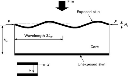
4.8 Wrinkling model in the combined thermal-mechanical condition: one-sided fire exposure and in-plane compression.
Here E2c is the Young’s modulus at the lower face of the core. The two Young’s moduli are related to the temperature field through the material degradation law in Section 4.3.
Assuming that during wrinkling the exposed skin displaces in the y direction following sinusoidal wave with a half wavelength Lw:
the membrane stress in the exposed skin is derived from the non-homogeneous theory of elasticity as:
In [4.29], the normalized wavelength is θ = πHc/Lw; the non-dimensional parameters, β* = β, Hc, η = Hs/Hc(D*E1s/E1c)1/3, and ![]() , where E1s is the Young’s modulus at the upper face of the exposed skin, and De is the bending stiffness of the exposed skin. The wrinkling stress σcr is achieved by minimizing the membrane stress with respect to the wavelength:
, where E1s is the Young’s modulus at the upper face of the exposed skin, and De is the bending stiffness of the exposed skin. The wrinkling stress σcr is achieved by minimizing the membrane stress with respect to the wavelength:
The numerical values of fcr for considerable ranges of the two non-dimensional parameters, β* and η, are tabulated in Gu and Asaro (2011).
The parameter β* is the natural logarithm of the ratio of the core’s Young’s modulus at interface with the unexposed skin to that at the interface with the exposed skin. If the highest possibility of this ratio is 10 000, β* ranges from 0 to 10. The typical material properties and dimensional lengths are used to estimate the values for η. Consider that Hs/Hc = 0.1, the non-dimensional bending stiffness D* = 2.9 (this is the case that E2s/E1s = 1000 for the exponential variation form), and E1s/E1c = 1000. Using the above numbers, η = 1.43. An estimate is that η ranges between 0 and 10 for most material systems. For the homogeneous core, β* = 0 and η is the only parameter that the wrinkling stress is dependent on. When the core thickness Hc approaches infinity, η and β approach zero, and fcr = 1.288.
The Winkler model, in which the core is approximated by a set of continuously distributed springs in the transverse direction, is a simplified model that overlooks the contribution of the shear deformation of the core. Considering the material gradients and following the similar procedure as that in Allen (1969), the wrinkling stress is written as:
where
Given the stiffness variation along the thickness, the wrinkling stress can be expressed by using the material degradation law [4.14]:
where E0s and E0c are the Young’s moduli of the skin and core at ambient temperature, respectively. The three temperatures, T1, T2 and T3, are denoted in Fig. 4.3. This expression separates the contributions of temperature field, materials and dimensional lengths. For linear stiffness variations in the skin and the core, we have:
where R(T) = [(Tref – T)/(Tref – Tr)]m for T ≤ Tref; R(T) = 0 for T > Tref. For constant temperature T1 in the skin and constant temperature T2 in the core, i.e. the upper bound temperature distribution, we have:
which is in a fairly simple form.
A thermal-mechanical simulation was performed to evaluate the wrinkling load in Gu and Asaro (2011). The exposed face is uniformly heated, where the temperature was linearly ramped up to the reference temperature 120 °C in 3600 seconds, and the unexposed face was kept at the room temperature. When the skin is above the reference temperature, it loses a significant portion of load bearing capability as shown by the degradation law in Section 4.3. So, the wrinkling load for a sandwich structure with thin skins in that temperature range may not be of interest. Figure 4.9 shows the wrinkling stresses normalized by the Young’s moduli at ambient temperature ![]() versus fire-heating time. The wrinkling stresses decrease as the fire-heating time increases. Examining the exact solution, at 3600 seconds the panel loses 33% of wrinkling load bearing capacity from that before heating. This shows again that the panel’s thermal performance considerably influences the mechanical load bearing capacity. The wrinkling stress obtained from the exact solution is larger than that from the Winkler model since the Winkler model does not consider the contribution of the shear stiffness of the core. When the heating time approaches zero, the two curves for the Winkler model approach each other since there are no thermal gradients before heating. The largest difference between the exact solution and the solution from the Winkler model with linear variation of material properties is about 18%.
versus fire-heating time. The wrinkling stresses decrease as the fire-heating time increases. Examining the exact solution, at 3600 seconds the panel loses 33% of wrinkling load bearing capacity from that before heating. This shows again that the panel’s thermal performance considerably influences the mechanical load bearing capacity. The wrinkling stress obtained from the exact solution is larger than that from the Winkler model since the Winkler model does not consider the contribution of the shear stiffness of the core. When the heating time approaches zero, the two curves for the Winkler model approach each other since there are no thermal gradients before heating. The largest difference between the exact solution and the solution from the Winkler model with linear variation of material properties is about 18%.
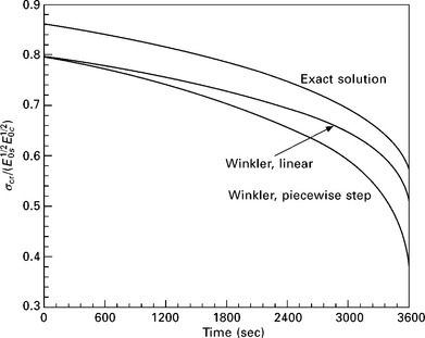
4.9 Wrinkling stress versus fire-heating time obtained from the combined thermal-mechanical simulation. From Gu and Asaro (2011). Used with permission from Elsevier.
4.6 Plastic micro-buckling
Micro-buckling which can lead to catastrophic failure is another failure mechanism of polymer matrix composite panels in compressive loading. A constitutive model, based on crystal plasticity theory (Asaro, 1983), was proposed for polymer matrix composites that experience both temperature rise resulting from fire exposure and strain rate dependence via interlaminar slip (Asaro et al., 2005; Ramroth et al. 2006). The constitutive model was implemented in finite element simulations to capture the plastic micro-buckling phenomena.
The kinematics of micromechanical deformation is illustrated in Fig. 4.10. The principal directions of the fibers are described by a set of mutually orthogonal unit base vectors, a1 a2 and a3. The bold faced variables denote vectors or tensors. The elastic response of the composite laminates is formulated on these base vectors. The material also deforms via slipping in the plane of the laminates, i.e. interlaminar shear. We introduce two slip systems aligned with the slipping directions s1 and s2, where the normal of the interlaminar plane is m. These three vectors in the deformed state are called ![]() , and m*, respectively. The total deformation from the reference configuration B0 consists of two portions: a viscoplastic deformation followed by an elastic deformation. The viscoplastic deformation occurs by the flow of the material through the lattice of the laminate via interlaminar shear. The spatial velocity gradient of the plastic flow is:
, and m*, respectively. The total deformation from the reference configuration B0 consists of two portions: a viscoplastic deformation followed by an elastic deformation. The viscoplastic deformation occurs by the flow of the material through the lattice of the laminate via interlaminar shear. The spatial velocity gradient of the plastic flow is:
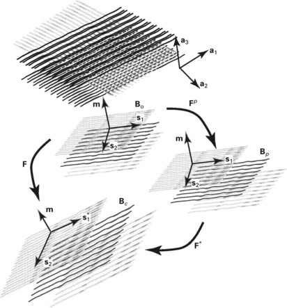
4.10 Kinematics of micromechanical deformation based on crystal plasticity theory to model polymer matrix composites. From Ramroth et al. (2006).
where Fp is the plastic deformation gradient, and ![]() is the rate of shearing on the α slip system. The value of Fp is obtained from the integration of [4.36] based on the incremental values of the associated variables. The viscoplastic deformation produces an intermediate configuration Bp. The deformed configuration Bc is reached by elastically distorting and rigidly rotating the laminate from Bp. The second portion of deformation is represented by the elastic deformation gradient F*, such that the total deformation gradient is:
is the rate of shearing on the α slip system. The value of Fp is obtained from the integration of [4.36] based on the incremental values of the associated variables. The viscoplastic deformation produces an intermediate configuration Bp. The deformed configuration Bc is reached by elastically distorting and rigidly rotating the laminate from Bp. The second portion of deformation is represented by the elastic deformation gradient F*, such that the total deformation gradient is:
The driving force for interlaminar shear is the resolved shear stress on the slip system, namely
In the above two expressions, τ = Jσ is the Kirchhoff stress, where σ is the Cauchy stress and J is the Jacobian of the deformation gradient. Here,![]() and
and ![]() are along the α slip direction and slip plane normal, respectively, in the deformed configuration.
are along the α slip direction and slip plane normal, respectively, in the deformed configuration.
The evolution of the viscoplastic deformation is cast in terms of the relationship between the rate of shearing and the resolved shear stress on the slip system by:
where sgn is the sign function; np is strain rate sensitivity exponent; ![]() is the reference strain rate; and gα is the slip system hardness, which varies with the shear strain of the slip system. A simple form for the slip system hardness is given by
is the reference strain rate; and gα is the slip system hardness, which varies with the shear strain of the slip system. A simple form for the slip system hardness is given by
where g0, g∞, h0, and h∞ are material constants.
Finally, the constitutive relation between the rate of Piola–Kirchhoff stress S and the rate of Green–Lagrange strain E is given by:
where L and Xα are related to the deformation gradient, the current stress, the slip system and the elasticity tensor.
An example to simulate micro-buckling progress using the constitutive model was given in Asaro et al. (2005). The specimen geometry was taken to be stubby so that the global buckling (Euler buckling) was precluded. The length of the specimen was 100 mm, the core thickness was 50 mm, and the skin thickness was 1.75 mm. The plane strain condition in the width direction was considered. The skin was initially perfectly bonded to the core through an adhesive thin layer of elements, which had the capability to simulate debonding when its failure criterion was reached. The degradation with respect to temperature rise for elastic material properties was modeled by the degradation law in Section 4.3; the degradation of the slip system hardness was also modeled similarly. The micromechanical constitutive model was used for skins with slip plane parallel to the surfaces of the skins in the reference configuration. The core was taken as isotropic elastic material. The micro-buckling was introduced by a small geometrical imperfection for the slip plane normal at the middle of the panel. The boundary condition was that one end of the specimen moved toward the other end along the axial direction with a velocity of 100 mm per second, whereas the other end was fixed in the axial direction. Figure 4.11 shows the load in the axial direction versus the displacement in the axial direction. The curve is linear up to the point where slip begins, as analyzed in the contour plots of plastic strain evolution at various representative times. After yielding, the micro-buckling or kink band mode develops, and the load drops dramatically. The plastic strain in the examined contour bands is between –5% and 5%. Figure 4.12 shows that after yielding and following the kink band formation, there is a reduction in the magnitude of the resolved shear stress on the slip system, which is similar for each node along the cross-section in the micro-buckled region.
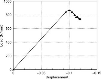
4.11 Axial load versus axial displacement for the plastic micro-buckling model. Figure is plotted using data in Asaro et al. (2005). Used with permission from Elsevier.
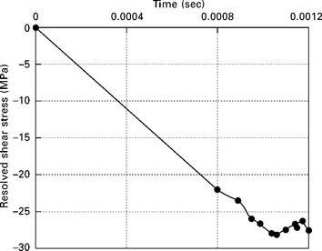
4.12 The resolved shear stress on the slip system versus fire-heating time for the plastic micro-buckling model. Figure is plotted using data in Asaro et al. (2005). Used with permission from Elsevier.
The finite element program implemented through the micromechanically-based constitutive model is capable of simulating a variety of failure modes, including the structural failure modes of global buckling and skin wrinkling, in addition to the material failure mode of plastic micro-buckling. In Ramroth et al. (2006), the constitutive model was used to simulate the failure of the single-skin panel discussed in Section 4.4. The panel was slender, not stubby, so that it was inherently prone to global buckling. With the same thermal and mechanical loads used in the example in Section 4.4, the calculated transverse displacement versus time curve did match that obtained from experiment given in Figure 4.6. The micromechanical constitutive model predicted the structural collapse behavior similar to that observed in experiments and formulated by the global buckling model in Section 4.4. The global buckling failure mode was expected since for the slender geometry one would not expect significantly local plastic shear to occur. This was confirmed by examining the contour plots of plastic strain which showed only very modest amounts of viscoplastic deformation developed up to the point of imminent collapse. Continued deformation from the onset of global buckling may cause local finite viscoplastic deformation which ultimately results in plastic mirco-buckling. But, the precise sequences of such phenomena remain to be analyzed in future studies. By the comparison of the results of the slender panel with the stubby panel, Ramroth et al. (2006) were able to conclude that micro-buckling may not be the primary mechanism that contributes to the onset failure of the structural panel, i.e. the panel with large in-plane dimensions. Experiments in Asaro et al. (1999, 2009b) did not show the local failure mechanism in structural panels.
Viscoelastic material behavior can be included in micromechanically based constitutive models. The viscoelastic behavior of polymer matrix composites under fire was tested and modeled by Boyd et al. (2006). Micro-buckling was investigated by applying the Budiansky–Fleck kink band solution (Budiansky and Fleck, 1993) with time and temperature dependent shear modulus, where time–temperature superposition was employed for the viscoelastic property (Bausano et al., 2006; Boyd et al., 2007).
4.7 Other aspects of structural integrity in fire
In addition to those aspects discussed in the above sections, there are others to explore the failure mechanisms of polymer matrix composites in structural fire integrity.
4.7.1 Thermal distortion
For a panel without external mechanical loads, if temperature rises uniformly along the thickness, the coefficient of thermal expansion makes it expand freely along the axial direction and no deflection is induced in the transverse direction. With the thermal gradient caused by fire, the thermal strain induced by the coefficient of thermal expansion is no longer uniform along the thickness such that the panel deflects, i.e. thermal distortion or thermal warping. The concern is that large deflection for large span panels in the thermal distortion may cause the structure to fail. In addition, for a sandwich panel, the thermal mismatch between the skins and the core can introduce significant stresses, which can lead to interfacial failure mechanisms.
Using the bending theory of non-homogeneous materials, the thermal distortion was evaluated in Gu and Asaro (2008a), where the curvature of the deformed neutral axis was given as:
where α is the coefficient of thermal expansion which is temperature dependent and the other terms are defined in previous sections. When the curvature is known, the transverse deflection can be obtained by considering the support condition at the two ends. The maximum deflection of the panel is:
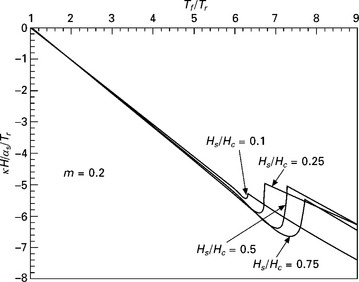
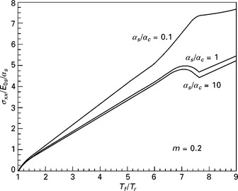
For both ends with roller support, Φ = 1/8; the maximum is attained at the center of the panel. For one end with roller support and the other with clamping support, Φ = 1/27; the maximum is attained at the distance 2l/3 from the clamping support end. The deflection is proportional to the square of the length of the panel. Figure 4.13 shows the influence of the ratio of the skin thickness to the core thickness on the curvature of a sandwich panel, and Fig. 4.14 shows the in-plane normal stress at the interface between the unexposed skin and the core (in the skin side). In the calculation, the unexposed face is assumed to be at room temperature, and the temperature at the exposed face rises to reach 120 °C in 3600 seconds. In Ramroth et al. (2006), the thermal distortion was considered in the micromechanically based simulation. In Asaro et al. (2009b), its effect was discussed in analyzing the experimental data of structural panels. Feih et al. (2007a) measured the transverse displacement caused by the thermal expansion during fire testing. Gu and Asaro (2010) discussed the influence of material nonlinearity on the thermal distortion and showed that with the increase of the hardening exponent the stress in the panel can be sufficiently large. The issues to be addressed for thermal distortion include the influences of chemical decomposition and geometrical nonlinearity, as well as the combined influence with external mechanical loads.
4.7.2 Failures induced by debonding, delamination, and cracking
Delaminations occurred in combined one-sided fire and compressive load tests along the ply interfaces of the composite laminates (Feih et al., 2007a; Asaro et al., 2009b). It was also observed that debondings between the skin and the core occurred in the sandwich panels in the global buckling tests (Asaro et al., 2009b). However, one finds limited fracture mechanics research for polymer matrix composites in fire (e.g. Lua et al., 2008; Luo et al., 2009). There is a lack of understanding of fracture behaviors at elevated temperatures for these materials and systems. One approach is to use the methodology of fracture mechanics (see Anderson, 1995) to discuss the onset fracture and the propagation of cracks. For non-homogeneous materials with mechanical property gradients induced by thermal gradients, the crack tip field is of the same form as that of functionally graded materials (Gu and Asaro, 1997a). For various crack configurations of functionally graded materials, stress intensity factors characterizing the elastic crack tip field were solved in Gu and Asaro (1997a, 1997b) and Gu et al. (1999). The application of J-integral (Rice, 1968) or domain integral (Shih et al., 1986) to functionally graded materials was discussed in Gu et al. (1999). For interfacial fracture, e.g. debondings between the skin and the core, investigations were comprehensively discussed in Hutchinson and Suo (1992). The influence of interfacial crack-tip plasticity on fracture behavior was studied by Shih and Asaro (1988) and Shih (1991). The objective of this study is to further understand crack behavior under combined thermal gradients and mechanical loads; to evaluate fracture mechanics theory as applied to polymer matrix composites under significant temperature rise; and to characterize the toughness of the temperature dependent materials.
4.7.3 Design of structural fire integrity
For panels made of conventional materials with high thermal conductivities, such as aluminum alloys, the tangent modulus method (Shanley, 1947) is used to design compressive load bearing capacity, where the collapse load is plotted against the temperature to obtain the allowable compressive load or permitted temperature range given the design criteria. Given the design safety factor, i.e. the scaling factor for the buckling load at ambient temperature, one locates from the collapse load curve the threshold temperature above which structural integrity is lost. Insulation and fire extinguishing requirements are therefore prescribed to prevent exceeding the threshold temperature for given fire protection time. Extending the methodology for aluminum alloy panels, Asaro et al. (1999) proposed to use the plot of collapse load versus temperature at the center of the single skin FRP panel to design its structural fire integrity. Given allowable compressive load or design safety factor, one locates the allowable temperature at the center of the panel. From this allowable temperature, the fire protection time is predicted from the temperature versus time curve determined from thermal analysis. For sandwich FRP panel, the curve of collapse load versus temperature at the interface between the exposed skin and the core was proposed in Asaro et al. (1999) for designing its structural fire integrity. It was found that for a wide range of cross-section geometries (skin thicknesses and core thicknesses), the collapse load curves fall into a tight band, and this would allow the design diagram for the material system to be developed with representative cross-section geometries.
Utilizing the solutions for buckling, skin wrinkling and other deformation modes under thermal gradients, the design methodology was programmed into software to automate the process for both single-skin panels and sandwich panels (Gu and Asaro 2008b, 2009). This program allows each panel to be designed precisely based on structural failure mechanisms, given its material property data and dimensional lengths. The program plots a design diagram, a curve of critical load (the minimum among known failure modes) versus heating time. If one specifies the allowable mechanical load in a design requirement, the program locates the fire protection time from the design diagram and then the permitted temperature from the temperature versus time curve at the exposed face. On the other hand, if one specifies the allowable temperature in a design requirement, the program locates the fire protection time from the temperature versus time curve at the exposed face and then the permitted mechanical load from the design diagram. This design methodology and procedure were verified with our experimental data obtained from specimens of roughly 1 m2 in in-plane size, and remain to be verified and validated with full-scale specimens for application to larger structures. Further development of the design methodology includes schemes for maintenance and repair based on the degradation of material properties with respect to combined influences of temperature, time, and residual material properties (after-fire properties). It also includes the extension to more complicated three-dimensional geometries, including stiffened panels and the exposure to non-uniform fire fluxes.
4.8 References
Allen, H.G.Analysis and Design of Structural Sandwich Panels. New York: Pergamon Press, 1969.
Anderson, T.L. Fracture Mechanics – Fundamentals and Applications, 2nd. Boca Raton, FL: CRC Press, 1995.
Asaro, R.J. Crystal plasticity. J Applied Mechanics. 1983; 50:921–934.
Asaro, R.J., Dao, M. Fire degradation of fiber composites. Marine Technology. 1997; 34:197–210.
Asaro, R.J., Dao, M., Myskowski, C.Structural fire safety of composite materials used on high speed craft as regulated by the IMO high speed craft code. The University of California at San Diego, 1999. [Technical Report of the Department of Structural Engineering].
Asaro, R.J., Krysl, P., Zhu, B., Ramroth, W.T. Rate dependent constitutive modeling of laminated FRP composites degraded by fire. Composite Structures. 2005; 68:399–408.
Asaro, R.J., Lattimer, B.Y., Mealy, C., Steele, G. Thermo-physical performance of a fire protective coating for naval ship structures. Composites Part A. 2009; 40:11–18.
Asaro, R.J., Lattimer, B.Y., Ramroth, W. Structural response of FRP composites during fire. Composite Structures. 2009; 87:382–393.
Bai, Y., Keller, T., Vallée, T. Modeling of stiffness of FRP composites under elevated and high temperatures. Composite Sci & Technology. 2008; 68:3099–3106.
Bausano, J.V., Lesko, J.J., Case, S.W. Composite life under sustained compression and one sided simulated fire exposure: characterization and prediction. Composites Part A. 2006; 37:1092–1100.
Birman, V., Bert, C.W. Wrinkling of composite-facing sandwich panels under biaxial loading. J Sandwich Structures & Materials. 2004; 6:217–237.
Birman, V., Kardomateas, G.A., Simitses, G.J., Li, R. Response of a sandwich panel subject to fire or elevated temperature on one of the surfaces. Composites Part A. 2006; 37:981–988.
Boyd, S.E., Lesko, J.J., Case, S.W. The thermal-viscoelastic, viscoplastic characterization of Vetrotex 324/Derakane 510A-40 through Tg. ASME J Engineering Materials & Technology. 2006; 128:586–594.
Boyd, S.E., Case, S.W., Lesko, J.J. Compression creep rupture behavior of a glass/vinyl ester composite subject to isothermal and one-sided heat flux conditions. Composites Part A. 2007; 38:1462–1472.
Budiansky, B., Fleck, N.A. Compressive failure of fiber composites. J Mech Phys Solids. 1993; 41:183–211.
Dao, M., Asaro, R.J. A study on failure prediction and design criteria for fiber composites under fire degradation. Composites Part A. 1999; 30:123–131.
Dodds, N., Gibson, A.G., Dewhurst, D., Davies, J.M. Fire behavior of composite laminates. Composites Part A. 2000; 31:689–702.
Dutta, P.K., Hui, D. Creep rupture of a GFRP composite at elevated temperatures. Computers and Structures. 2000; 76:153–161.
Fagerberg, L., Zenkert, D. Imperfection-induced wrinkling material failure in sandwich panels. J Sandwich Structures & Materials. 2005; 7:195–219.
Feih, S., Mathys, Z., Gibson, A.G., Mouritz, A.P. Modelling the compression strength of polymer laminates in fire. Composites Part A. 2007; 38:2354–2365.
Feih, S., Mathys, Z., Gibson, A.G., Mouritz, A.P. Modelling the tension and compression strength of polymer laminates in fire. Composites Sci & Technology. 2007; 67:551–564.
Feih, S., Mouritz, A.P., Mathys, Z., Gibson, A.G. Tensile strength modeling of glass fiber-polymer composites in fire. J Composite Materials. 2007; 41:2387–2410.
Feih, S., Mouritz, A.P., Mathys, Z., Gibson, A.G. Fire structural modeling of polymer composites with passive thermal barrier. J Fire Sciences. 2010; 28:141–160.
Gdoutos, E.E., Daniel, I.M., Wang, K.-A. Compression facing wrinkling of composite sandwich structures. Mechanics of Materials. 2003; 35:511–522.
Gibson, A.G., Wu, Y.S., Chandler, H.W., Wilcox, J.A.D., Bettess, P. A model for the thermal performance of thick composite laminates in hydrocarbon fires. Rev L’Inst Francais Petrole. 1995; 50:69–74.
Gibson, A.G., Wright, P.N.H., Wu, Y.S., Mouritz, A.P., Mathys, Z., Gardiner, C.P. Modelling residual mechanical properties of polymer composites after fire. Plastics, Rubber & Composites. 2003; 32:81–90.
Gibson, A.G., Wright, P.N.H., Wu, Y.S., Mouritz, A.P., Mathys, Z., Gardiner, C.P. The integrity of polymer composites during and after fire. J Composite Materials. 2004; 38:1283–1307.
Gibson, A.G., Wu, Y.S., Evans, J.T., Mouritz, A.P. Laminate theory analysis of composites under load in fire. J Composite Materials. 2006; 40:639–658.
Gu, P., Asaro, R.J. Cracks in functionally graded materials. Int J Solids & Structures. 1997; 34:1–17.
Gu, P., Asaro, R.J. Crack deflection in functionally graded materials. Int J Solids & Structures. 1997; 34:3085–3098.
Gu, P., Asaro, R.J. Structural buckling of polymer matrix composites due to reduced stiffness from fire damage. Composite Structures. 2005; 69:65–75.
Gu, P., Asaro, R.J. Distortion of polymer matrix composite panels under transverse thermal gradients. Composite Structures. 2008; 82:413–421.
Gu, P., Asaro, R.J. Designing polymer matrix composite panels for structural integrity in fire. Composite Structures. 2008; 84:300–309.
Gu, P., Asaro, R.J. Wrinkling of sandwich polymer matrix composite panels under transverse thermal gradients. Fire Safety Journal. 2008; 43:151–160.
Gu, P., Asaro, R.J. Designing sandwich polymer matrix composite panels for structural integrity in fire. Composite Structures. 2009; 88:461–467.
Gu, P., Asaro, R.J. Influence of material nonlinearity on thermal distortion of polymer matrix composite panels. Composites Part B. 2010; 41:58–66.
Gu, P., Asaro, R.J., Skin wrinkling of sandwich polymer matrix composite panels subjected to fire exposure. Thin-Walled Structures 2011;, doi: 10.1016/j.tws.2011.10.008.
Gu, P., Dao, M., Asaro, R.J. A simplified method for calculating the crack-tip field of functionally graded materials using the domain integral. J Appl Mechanics. 1999; 66:101–108.
Gu, P., Dao, M., Asaro, R.J. Structural stability of polymer matrix composite panels in fire. Marine Structures. 2009; 22:354–372.
Henderson, J.B., Wiecek, T.E. A mathematical model to predict the thermal response of decomposing, expanding polymer composites. J Composite Materials. 1987; 21:373–393.
Henderson, J.B., Wiebelt, J.A., Tant, M.R. A model for the thermal response of polymer composite materials with experimental verification. J Composite Materials. 1985; 19:579–595.
Hollaway, L.C., Head, P.R.Advanced Polymer Composites and Polymers in the Civil Infrastructure. Amsterdam: Elsevier, 2001.
HSCInternational code of safety for high-speed craft. London: Halstan & Co. Ltd., 1995. [chapter 7, International Maritime Organization (IMO)].
Hutchinson, J.W., Suo, Z. Mixed mode cracking in layered materials. Advances in Applied Mechanics. 1992; 29:63–191.
Kardomateas, G.A. Wrinkling of wide sandwich panels/beams with orthotropic phases by an elasticity approach. ASME J. Applied Mechanics. 2005; 72:818–825.
Krysl, P., Ramroth, W.T., Stewart, L.K., Asaro, R.J. Finite element modelling of fiber reinforced polymer sandwich panels exposed to heat. Int J Num Methods Engin. 2004; 61:49–68.
Lattimer, B.Y., Ouellette, J. Properties of composite materials for thermal analysis involving fires. Composites Part A. 2006; 37:1068–1081.
Looyeh, M.R.E., Bettess, P. A finite element model for the fire-performance of GRP panels including variable thermal properties. Finite Elements in Analysis and Design. 1998; 30:313–324.
Looyeh, M.R.E., Bettess, P., Gibson, A.G. A one-dimensional finite element simulation for the fire-performance of GRP panels for offshore structures. Int J Num Meth for Heat & Fuild Flow. 1997; 7:609–625.
Lua, J., O’Brien, J., Key, C.T., Wu, Y., Lattimer, B.Y. A temperature and mass dependent thermal model for fire response prediction of marine composites. Composites Part A. 2006; 37:1024–1039.
Lua, J., Shi, J., Des Jardin, P., Case, S.W. Fire simulation and thermal-mechanical damage prediction tool for composite structures. Proceedings of the 49th AIAA/ASME/ASCE/AHS/ASC Structures, Structural Dynamics and Materials Conference, Schaumburg, IL, 2008.
Luo, C.L., Chen, L., Lua, J., Shi, J. A 3D Abaqus toolkit for thermal-mechanical damage prediction of composite sandwich structures subjected to fire. Proceedings of the 50th AIAA/ASME/ASCE/AHS/ASC Structures, Structural Dynamics and Materials Conference, Palm Springs, CA, 2009.
Mouritz, A.P. Post-fire flexural properties of fibre-reinforced polyester, epoxy, and phenolic composites. J Materials Science. 2002; 37:1377–1386.
Mouritz, A.P. Simple models for determining the mechanical properties of burnt FRP composites. Materials Sci & Engineering. 2003; 359A:237–246.
Mouritz, A.P., Mathys, Z. Post-fire mechanical properties of marine polymer composites. Composite Structures. 1999; 47:643–653.
Mouritz, A.P., Mathys, Z. Post-fire mechanical properties of glass-reinfored polyester composites. Composite Sci & Technology. 2001; 61:475–490.
Mouritz, A.P., Mathys, Z., Gardiner, C.P. Thermomechanical modeling the fire properties of fibre-polymer composites. Composites Part B. 2004; 35:467–474.
Mouritz, A.P., Feih, S., Kandare, E., Mathys, Z., Gibson, A.G., Des Jardin, P.E., Case, S.W., Lattimer, B.Y. Review of fire structural modelling of polymer composites. Composites Part A. 2009; 40:1800–1814.
Plantema, F.J.Sandwich Construction – the Bending and Buckling of Sandwich Beams, Plates, and Shells. New York: Wiley, 1966.
Ramroth, W.T., Asaro, R.J., Zhu, B., Krysl, P. Finite element modeling of fire degraded FRP composite panels using a rate dependent constitutive model. Composites Part A. 2006; 37:1015–1023.
Rice, J.R. A path independent integral and the approximate analysis of strain concentration by notches and cracks. J Applied Mechanics. 1968; 35:379–386.
Shanley, F.R. Inelastic column theory. J Aeronautical Sciences. 1947; 14:261–268.
Shih, C.F. Cracks on biomaterial interfaces: elasticity and plasticity aspects. Materials Sci & Engineering. 1991; A143:77–90.
Shih, C.F., Asaro, R.J. Elastic-plastic analysis of cracks on biomaterial interfaces: Part I – small scale yielding. J Applied Mechanics. 1988; 55:299–316.
Shih, C.F., Moran, B., Nakamura, T. Energy release rate along a three-dimensional crack front in a thermally stressed body. Int J Fracture. 1986; 30:79–102.
Springer, G.S. Model for predicting the mechanical properties of composites at elevated temperatures. J Reinforced Plastics & Composites. 1984; 3:85–95.
Trelles, J., Lattimer, B.Y. Modelling thermal degradation of composite materials. Fire & Materials. 2007; 31:147–171.
Vonach, W.K., Rammerstorfer, F.G. Wrinkling of thick orthotropic sandwich plates under general loading conditions. Archive of Applied Mechanics. 2000; 70:338–348.
Wu, Y.S., Wilcox, J.A.D., Gibson, A.G., Bettess, P.Design of composite panels for mechanical and fire performance. University of Newcastle-upon-Tyne, 1993. [Final report prepared for British Gas plc].
Zenkert, D.An Introduction to Sandwich Construction. London: The Chameleon Press, 1995.