
Failure of polymer matrix composites in marine and off-shore applications
Abstract:
Composites are widely used in marine applications and there is considerable experience of their behaviour in service. This chapter first describes the different materials used for marine structures. Then a series of tests which have been developed to simulate the loading of marine structures, both for surface vessels and underwater structures, will be presented, and examples of failures will be described.
10.1 Introduction
The use of composite materials for marine applications is now widespread [1]. For over 50 years most pleasure boats have been manufactured from glass fibre reinforced thermosetting resins, and the long-term behaviour of these materials has generally been quite satisfactory. For floating vessels (pleasure boats, ships, buoys, etc.), even if the loads on the structure during its service life are not completely known, the design loads used in the certification design codes (static and dynamic loading pressures) generally lead to conservative dimensioning. A recent ISO document summarizes this experience [2]. Hydrodynamic loading due to waves, wind, and swell is quite complex and for naval structures made of composite materials today a global model taking into account all these parameters is too complex to perform. The main parameter governing the majority of these designs is the rigidity of the structure, so high safety factors in terms of strength are generally achieved, and failure of such structures under normal service conditions are very rare.
The main problems encountered are due to unexpected loading, such as rigid impact (collision) which may generate internal structure degradation (e.g. disbonding of stiffeners) or hull damage. increasing use of sandwich structure has generated new problems related to the shear behaviour of the core or weak interfaces between core and skin. However, at this stage it appears that most of the problems can be attributed to manufacturing problems. Although new fabrication techniques are now being used in this sector (e.g. infusion, prepreg, etc.), the quality of materials can be quite poor in comparison with other industrial sectors. The cost of fabrication of composite materials for marine structures is generally not comparable to the cost of fabrication in the aeronautical sector, and benefits from large series such as those obtained in the automotive sector are not widely available as boat production quantities are relatively small (tens or hundreds rather than thousands).
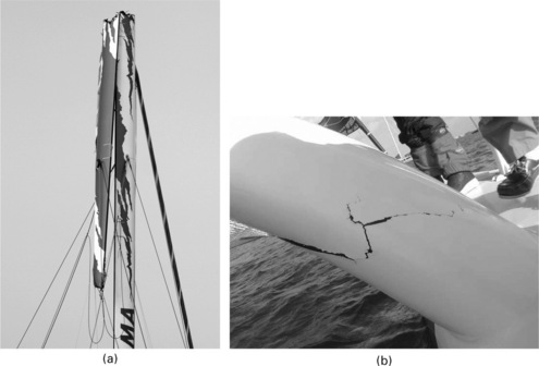
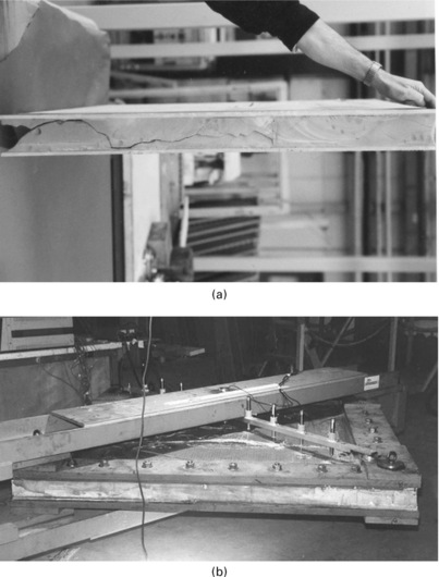
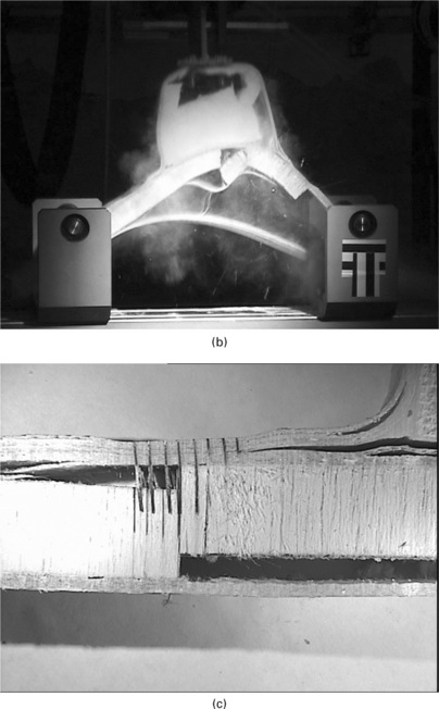
Racing sail boats are a very interesting platform for material development, analogous to Grand Prix motor racing, and have enabled significant technological improvements to be tested. The design of such structures is optimized in terms of performance, and the use of high-performance materials and fabrication techniques (autoclave) push the structures to their limits. unexpected failures have occurred, affecting different parts of the structures such as appendices (e.g. masts, foils) or the main hull structures. Buckling of masts, collapse of foils by overloading, degradation of sandwich panels due to wave impact are some recent examples (Fig. 10.1).
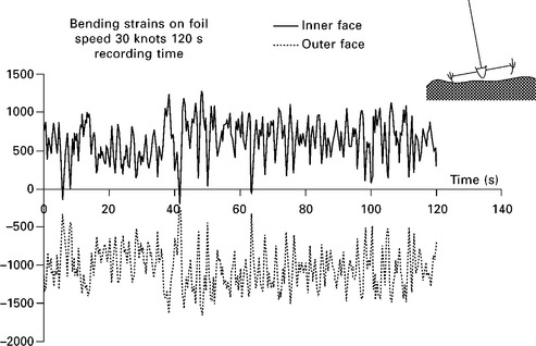
Difficulty in appreciating dynamic loading (Fig. 10.2) is the main problem, and studies to determine the real loading have been performed on some platforms [3, 4], but data are insufficient. Fabrication problems could be evoked here, but inadequate knowledge of the properties of the prototype composite materials employed is also a recurrent problem. For underwater applications knowledge of the loading is often much simpler, as external pressure is directly related to the immersion depth. However, for this type of application one of the main difficulties remains the behavior of composite materials under compression loading. Under hydrostatic pressure, the collapse is generally governed by the buckling of the structure and/or by overloading in terms of compressive strength of the material. This point has been addressed and will be described below. Manufacturing parameters have a strong influence on the compressive properties of the material (e.g. voids, waviness, compaction). For submarine applications quite thick composites may be required (up to 10 cm), and an additional parameter which may influence the behaviour of the structure and which is conditioned by the manufacturing parameters is the residual stresses.
Syntactic foam can be considered as composite material. This material, composed of hollow micro-spheres in polymer matrices, is widely used in the deep sea environment for buoyancy and thermal insulation applications, particularly in the offshore oil and gas industry. It is currently the object of detailed studies in order to improve the understanding of the behavior of such materials in severe environments (high hydrostatic pressures up to 30 MPa, contact with hot water up to 120 °C).
Common to all these applications is the need to understand the effect of sea water on the long-term behaviour of polymeric materials, and many published references are available (e.g. [5]). The coupling of water ingress and loss of mechanical properties is at this stage not completely understood but has been the subject of several recent studies [6, 7]. However, in general with the safety factors used in the design of classical marine structures and the large material thicknesses required to resist hydrostatic pressures for deep-sea applications, hydrolytic degradation is not a major problem. Recent work on the use of composites for renewable marine energy (e.g., tidal turbines, thermal energy), where long-term durability is critical due to reduced access for maintenance, is generating renewed interest in long-term ageing [8].
Overall, the use of polymer matrix composites in marine and off-shore applications is expanding and a thorough understanding of damage mechanisms is essential if costly failures are to be avoided. This chapter will first describe the different materials used for marine structures. Then a series of tests which have been developed to simulate the loading of marine structures, both for surface vessels and underwater structures, will be presented and examples of failures will be described. The chapter will end with a short section on modelling of failure, but the main emphasis here is on experimental results.
10.2 Material types
The materials used for marine structures have traditionally been quite different from those developed for aerospace applications. E-glass fibres are the most popular marine composite reinforcement, and unsaturated polyester resins are widely used, particularly in the pleasure boat industry. The resulting composites are manufactured by hand lay-up, roller impregnation of woven and mat reinforcements (Fig. 10.3(a)), with liquid resins. This results in a low-cost, low-performance product, with fibre volume content around 30%. In recent years, however, more stringent environmental regulations and requirements for improved performance have led to changes in both material and manufacturing methods. In order to limit styrene emissions, a range of new resin formulations was developed and these are now widespread. Unfortunately, they tend to be more brittle than traditional resins [9]. Infusion-based manufacturing methods have also been developed, resulting in higher fibre contents and improved quality.


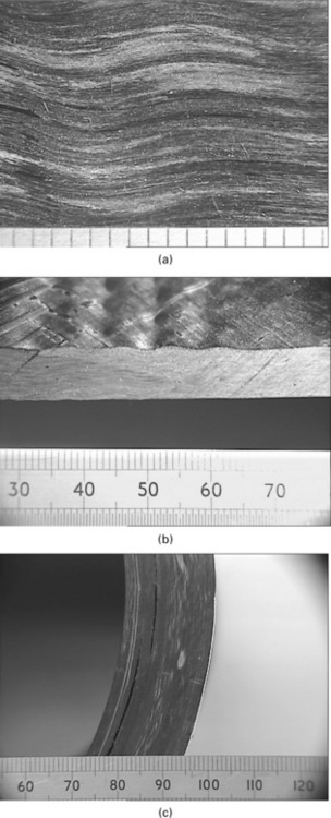
10.3 Common marine composites: (a) Rovimat glass reinforcement for hand laminated glass/polyester, (b) sandwich, glass/polyester on 20 mm thick PVC (poly(vinyl chloride) foam core, (c) filament wound ±55 ° glass/epoxy tube, (d) glass micro-spheres used in syntactic foams.
A second type of material frequently used in marine structures uses the sandwich concept. Glass/resin facings are laminated onto foam (usually PVC) or balsa wood cores. This provides improved stiffness for lower weight (Fig. 10.3(b)). The foam shear properties are proportional to the core density which typically ranges from 60 to 200 kg/m3 for PVC. Balsa wood is a natural material and is available in 100, 150 and 250 kg/m3 densities.
The third type of material we will discuss here is filament wound composites. These are of particular interest for cylindrical underwater structures and the most popular material is a glass reinforced epoxy (Fig. 10.3(c)). Fibre contents are higher than for laminated composites, typically around 60% by volume.
Finally, a fourth material essential for many underwater applications is syntactic foam. This is composed of thin wall hollow glass spheres of 10 to 100 microns diameter (Fig. 10.3(d)) in a polymer matrix, often epoxy. Densities in the range 300 to 600 kg/m3 are used, hydrostatic crush strength increases with density.
The materials described above are those which represent the majority of marine applications. As with all industries there are of course exceptions, for example racing yachts use high performance carbon fibre reinforced composites and honeycomb sandwich closer to those employed in the aerospace sector.
10.3 Failure of composite materials for surface vessels
10.3.1 Laminate material testing
The characterization of marine laminates is now well established. Many of the standard test methods developed for other composites can be applied to these materials, and the main concern is the size of woven patterns which may require larger specimens than for other composites. Tensile (at 0 °, 45 ° and 90 ° to the main reinforcement orientation), flexural and interlaminar shear (ILSS) tests are most common, and the main concern is often to establish laminate quality. Significant levels of porosity are not unusual and large test programmes have been performed to obtain the ‘typical’ composite data provided in the ISO 12215 standard [10]. Hundreds of specimens of glass/rovimat composites were tested. First damage in tension in the form of matrix cracks in off-axis fibres occurs at low strain levels, around 0.3% for the standard polyester resins. Final failure occurs much later, at strains around 2%. Marine laminates are as difficult to characterize under shear and compression loading as other composites, with many standard tests none of which is completely satisfactory to obtain stiffness and strength data. The latter will be discussed in more detail below, as compression behaviour is critical in both mast and underwater applications.
10.3.2 Sandwich core behaviour
The cores of sandwich materials are also subjected to shear and compression, so tests concentrate on these loadings. Stiffness data are relatively easy to obtain but it is more difficult to generate reliable failure data. Foam cores are usually assumed to be isotropic, though density may not be constant through the thickness, and the standard tests (ASTM C273 for shear between plates and ASTM C365 for through thickness compression) are widely used. However, in shear tests the failure generally initiates at the sample ends where tensile stresses can be significant (Fig. 10.4(a)). When balsa wood is tested in shear, failure is dominated by heterogeneities such as the bonded region between wood blocks (Fig. 10.4(b)). In compression, final failure is often caused by barrelling due to friction restraint at the loading platens.

10.4 Shear tests on core materials: (a) shear failure in foam (3-rail fixture, central rail loaded in tension), (b) shear failure of balsa (2-rail).
Various improved shear tests have been proposed [11] but these tend to require more specimen preparation, so they are not popular. Large sandwich material databases have been developed in various military programmes, but few data are available in the open literature [12].
It is often preferred to test the complete sandwich, as this allows manufacturing quality to be assessed. In this case the facing/core interface may be the weak link, and tests have been developed specifically to evaluate this region. For example, interface crack propagation energies can be measured under tensile or shear loading [13, 14].
10.3.3 Structural tests
In order to simulate the loading of marine structures, a number of panel tests have been developed. This section will describe some of these, and show examples of the failure modes encountered.
Lateral pressure loading of panels
As noted in Section 10.1, the dimensioning of boat structures is based on apparent loading pressure. It therefore seems logical to imagine a test which allows panels to be loaded by a transverse pressure in order to study their response. Various authors have described such tests [15–17]. A test frame was developed to produce this type of loading in a European project in 1991 [18] and it has been used in several projects since then, both to evaluate a range of laminated and sandwich materials and to validate numerical models. Figure 10.5 shows a sandwich panel on the test frame. Here a wide sandwich beam is loaded from below using air cushions and two top hat stiffeners provide the reaction points. This allows the panel edge to be observed and damage to be followed near stiffeners on the free edge, but it is not very representative of sandwich applications. In other tests the panel was bonded to a rigid steel frame on all four sides.
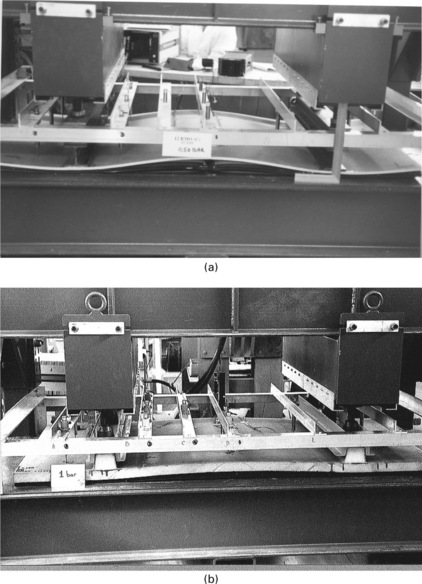
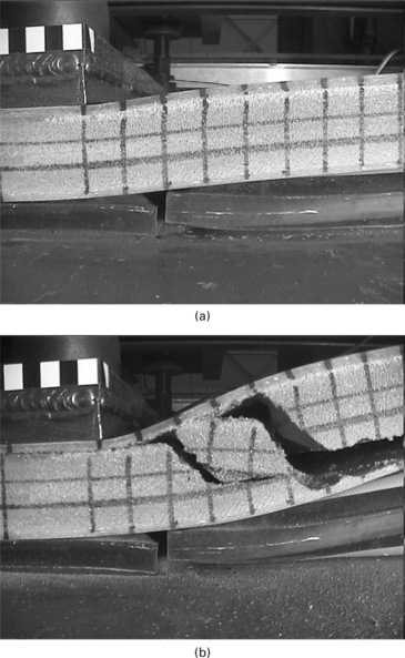
The test facility is dimensioned to allow tests on panels of dimensions up to 2 m long and 1 m wide with up to 5 bars pressure (100 tons reaction force) and specimens tested to date have included wide beams and stiffened panels of both laminates and sandwich materials. Designing tests to produce realistic failures is not straightforward and preliminary numerical modelling is usually necessary. This test has been used to examine PVC core shear failure near a stiffener due to lateral pressure loading [19]. Figure 10.6 shows edge view images just before and during shear failure.
In-plane shear
In some cases, for example that of an internal ship bulkhead, the predominant loading is not lateral pressure but in-plane shear. Picture frame tests have been proposed for other composite shear studies [20] and this was the approach followed here (Fig. 10.7(a)). Careful design was necessary to avoid premature failure in the frame corners. A preliminary numerical study was performed to analyse this, and reinforcement layers were added around the sandwich panel edges. Figure 10.7(b) shows the test fixture. Tests were performed on two nominally identical panels, 1.8 × 1.8 m square, made up of 8.7 mm thick woven glass/phenolic skins on a 70 mm thick phenolic foam core. Failure of the first panel occurred at a load between 130 and 140 tons, but considerable noise was apparent at loads above 80 tons. After cutting the panel it was clear that the core was heavily damaged (Fig. 10.8(a)), while the skins were apparently intact. The final failure mode involved local buckling. The failure of the second panel also occurred at a load of around 130 tons. There was again considerable noise emitted at lower loads. The final failure mode involved a symmetrical buckling and a complete rupture of the upper skin, with some wrinkling of the lower skin (Fig. 10.8(b)). The central panel strain measurements in the loading direction at a load of 60 tons were 1677 and 1713 micro-strain for Panels 1 and 2 respectively, i.e. within about 2% of each other. These data were used to correlate with numerical analyses.

Hard impact
While quasi-static loads in service can usually be estimated or measured, many failures in marine structures are due to dynamic loads. Two types of loading can be envisaged, hard and soft impact. The former involves a rigid impacter, while in the latter the impacter can deform during the impact. Hard impacts can range from a dropped tool on deck to collision with a floating object. They are often simulated by a falling metallic weight test, designed to evaluate the response of a structure to a controlled impact with a known energy. Soft impacts will be described in the next section and are designed to simulate wave loading.
The main concerns in hard impact testing are the boundary conditions. The aim is to test the sample, not the restraining fixture, and Olsson has discussed the requirements for this in some detail [21]. Figure 10.9 shows an example of a hard impact test set-up, a steel impacter is released and guided onto a panel simply supported on a cylindrical support. An anti-rebound device, using a spring-loaded clamp activated by diodes, allows a single impact to be applied.

According to the laminate or sandwich material construction, the geometry and the impact energy, damage may vary from slight matrix cracking to complete perforation. Figure 10.10 shows examples of damage in sandwich panels.
Soft impact
Wave impact damage is not uncommon on fast composite craft, and is the result of single or repeated pressure pulses on the hull structure [22]. There is no standard test to evaluate wave impact and there are few published descriptions of tests to examine this type of loading. In the recent ISO procedure for dimensioning hull structures [2] a full size impact test is suggested to validate new designs. Such tests have been performed (e.g. [23]) (Fig. 10.11), but this is clearly a very expensive option.

An intermediate alternative is to work on boat sections. Hayman et al. used this approach to examine how pressure varies during a water impact on composite sandwich structures [24]. Small-scale models have also been used in drop tests to obtain slamming pressure data [25], while a recent study used panels instrumented with Bragg gratings dropped into a wave tank [26]. Another recent paper describes a test set-up specifically designed to examine controlled velocity impacts of panels on water, but this requires a complex, dedicated test machine [27].
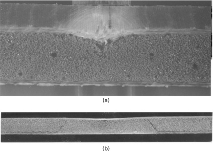
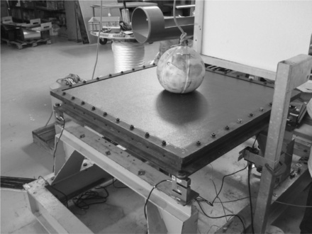
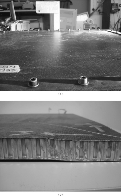
An alternative approach is based on drop weight testing, with a medicine ball as the soft impacter [28]. This is an elastomer envelope containing sand or metal pellets, which can be dropped from different heights onto 1 m2 panels rigidly fixed in a frame (Fig. 10.12). While initially the test was simply designed to compare different types of sandwich panel placed on the floor, both the boundary conditions and instrumentation have been progressively improved in order to be able to provide quantitative data for comparisons with results from numerical modelling [29, 30]. High-speed photography allows the ball shape to be quantified during the impact. Incident energies over 3 kJ can now be obtained by dropping balls weighing up to 45 kg from heights up to 7 m. Figure 10.13 shows an example of a sandwich panel failure in a carbon composite skinned aluminium foam core sandwich. The panel was sectioned using high-pressure water jet cutting after a depression was noted in the centre of the impacted surface (Fig. 10.13(a)), and inspection of the central region (Fig. 10.13(b)) revealed core shear failure.
10.13 Soft impact on aluminium honeycomb core sandwich panel: (a) panel after impact, (b) shear failure in core.
Other materials may show core crushing, seen in some Nomex™ honeycombs (Fig. 10.14(a)), or skin failures, if the facings are thin and the core is a ductile foam (Fig. 10.14(b)).

Assemblies
Failures in composite structures are usually associated with regions of stress concentration, and assemblies are particularly vulnerable. Design of the interface region between panels and stiffeners, for example, is critical if premature debonding is to be avoided. One example of such assemblies was examined in a European project [31], in which pultruded composite stiffeners were adhesively bonded to sandwich panels. The geometry of the stiffener end was studied in detail using numerical models to optimize the load transfer. Figure 10.15 shows the resulting stiffener shape before testing, together with two images showing the failure mechanism (crack propagation within the pultruded composite) after testing.

10.15 Bonded stiffener assembly: (a) stiffener on 2 × 1 m panel before testing, (b) end of stiffener after testing, (c) section through stiffener after test.
Lateral pressure loading resulted in failure within the composite, not in the adhesively bonded region. The low through-thickness strength of laminated composites, leading to delamination, is frequently the weak link in composite structures and has resulted in extensive studies of through-thickness reinforcement. One example is the use of ‘z-pins’ to improve the strength of composite stiffeners laminated onto a sandwich panel [32]. These are pultruded carbon composite pins which can be inserted into composite or prepreg lay-ups before curing.
In order to investigate their efficiency, top hat stiffener samples were prepared by overlaminating layers of glass/epoxy onto a balsa sandwich by hand lay-up. In the standard series, three overlaminated layers were applied. A second series was then prepared with identical geometry except for the addition of carbon z-pins (through-thickness reinforcement) in the overlaminated area on both sides of the stiffener during wet lay-up (Fig. 10.16).

When the standard assembly is subjected to both quasi-static and high rate pull-off at 1 m/s, it is the overlaminated stiffener which debonds (Fig. 10.17(a)). With the pinned samples no debonding occurs (Fig. 10.17(b)) and final failure is the result of sandwich shear followed by lower skin debonding. Figure 10.17(c) shows the pinned sample after test. There is no propagation; failure has occurred by shear within the balsa.

Simulation of mast loading
As noted in Section 10.1, failures do sometimes occur in service, and one of the most highly loaded elements in racing yachts is the mast (Fig. 10.1(a)). This is a carbon fibre reinforced composite tube, often over 30 m long, which is loaded in compression by the rigging. Designing such structures is complex as both global and local failure modes must be considered. One of the difficulties is that it is very hard to obtain reliable input data from standard test methods on unidirectional specimens. Failures are often not caused by compression, and it is very easy to underestimate compression strength. This problem is accentuated as higher modulus materials are tested (fibres with modulus up to 600 GPa), and such materials are very attractive for masts to ensure stiffness with minimum weight. Various methods have been employed to obtain improved compression data, including modifying sample geometry (Fig. 10.18(a)), and testing tubes (Fig. 10.18(b)) [33]. One conclusion from this work is the need to account for the restraining effect of adjacent off-axis plies, not just the unidirectional contribution, when designing a structure loaded in compression.

10.4 Failure of composite materials for underwater structures
A large number of studies have been carried out into the use of lightweight polymer-based materials for deep sea applications. These have included the development of equipment for the offshore industry, such as risers and separator modules [34, 35], oceanographic applications and underwater vehicles, from small AUVs (autonomous underwater vehicles) [36, 37] to military submarines [38]. In all cases weight reduction is the main incentive. This section is divided into two parts: first, the response of filament wound materials to external pressure loading will be described, then the failure behaviour of syntactic foams, an essential element in buoyancy structures, will be presented.
10.4.1 Failure of filament wound materials
The principal load on these structures is hydrostatic pressure P, which is in direct relation with the immersion depth, H, according to the expression P = 0.001H + 0.05 × 10⁻⁶ H2. Most structures are cylindrical in order to withstand this hydrostatic loading, and filament winding is the most common manufacturing method for these applications.
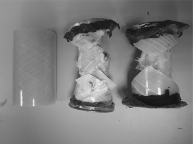
Design is generally based on codes extrapolated from metal design, and attention must be paid to the problems posed by anisotropic materials with limited knowledge of compressive properties. In the central section of a closed tubular structure, hoop stresses are twice axial stresses, and the benefits of using composites are based on choosing materials with optimized orientation of the fibres. Often a ±55 ° fibre orientation is chosen with respect to the tube axis, as it is easy to manufacture and widely used for tubes subjected to internal pressure. It has been observed that there are two main failure mechanisms for collapse of these cylinders: global buckling of the structure or local overloading (Fig. 10.19). As thickness-to-diameter ratio is increased, buckling is replaced by biaxial compression failure.
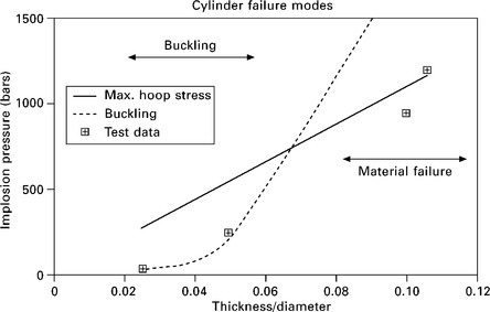
10.19 Failure modes for composite cylinders under hydrostatic pressure loading. Squares indicate test results.
The fibre orientation can be optimized through the thickness of the material [39] to improve buckling behaviour, which results in an improved solution. Unfortunately test results do not always agree with model predictions, and extensive pressure testing is still used (Fig. 10.20).

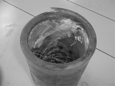
Considering first buckling behaviour, there are various simplified analytical expressions. However, today finite element codes are usually employed to study the response of thin composite tubes under external pressure. Attention must be paid to the design of end closures, in order to limit local stress concentrations due to contact between closures and the tube end [40]. If this is not considered, premature local failure will be observed (Fig. 10.21).
Global buckling has to be carefully analysed. The buckling mode of the structure is governed by the circumferential and axial rigidities of the structure, the thickness/diameter ratio and the length of the tube. Most often the buckling mode observed is Mode 2 corresponding to an ovalization of the central section of the structure, though in some cases Mode 3 (triangulation) can occur. Figure 10.22 shows examples of results for thin glass and carbon cylinders.
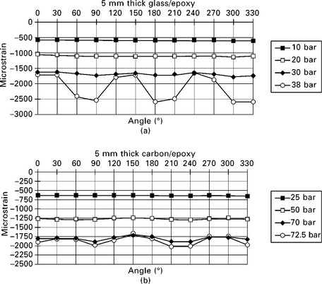
10.22 Internal hoop strain measurements indicating Mode 2 buckling, central section, 5 mm thick × 175 mm diameter ±55 ° cylinders: (a) glass, (b) carbon.
There is a significant improvement in buckling behaviour when carbon replaces glass as the former is considerably stiffer and buckling is governed by stiffness. The behaviour of the structure is mainly elastic, and it is difficult to detect local damage to the material before sudden collapse of the structure.
When thicker cylinders are tested, the difference between the performance of glass and carbon reinforced materials is less obvious. The failure strains are much higher than for the thin wall cylinders and the glass deforms more than the carbon. There is still a significant weight gain (the wound carbon cylinder is 25% lighter than the glass), but the implosion pressures are now very similar (Fig. 10.23).

10.23 Internal hoop strain measurements indicating Mode 2 buckling, central section, 18 and 19 mm thick × 175 mm diameter ±55 ° cylinders: (a) glass, (b) carbon.
This is a surprising result considering the intrinsic fibre properties, but compression failure is very dependent on manufacturing quality and defects [41, 42]. Carbon fibre composites, in particular with high thickness (above about 10 mm), appear more sensitive than glass to residual stresses, resulting in fibre micro-buckling, ply buckling and delaminations (Fig. 10.24).
10.24 Examples of defects in carbon composite cylinders: (a) in-plane fibre waviness, (b) out-of-plane ply waviness, (c) delamination in thick wall cylinder.
Nevertheless, large demonstration structures have already been manufactured with carbon fibre for deep sea exploration (AUV) and tests to 600 bars have been performed successfully [43]. High diameter tubes (carbon fibre epoxy) are also used for submarine missile torpedo tubes, one of the largest applications of high-performance composite underwater.
10.4.2 Influence of impact on cylinder failure modes
One of the concerns with composite tubes is their damage tolerance. A large programme of tests was performed on glass and carbon reinforced composite cylinders to examine the development of impact damage and then to establish its influence on pressure test behaviour and failure modes [44, 45]. Figure 10.25 shows an example of the delamination damage resulting from an 8 J impact on a carbon/epoxy tube. When impacted tubes are subjected to external pressure testing, the global failure mode usually observed is no longer noted, and a premature local implosion is seen (Fig. 10.26). A more detailed discussion of the influence of defects in composite tubes can be found in [42].

10.26 Change in implosion failure mode after impact. Centre: global implosion failure; right: local implosion failure after central impact.
Failure of syntactic foams
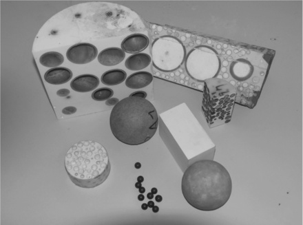
As shown in Fig. 10.3(d), syntactic foams are simply polymers, usually epoxy, filled with thin-wall glass spheres. The main damage mechanism, which results in loss of buoyancy of the material, is damage to these spheres. Initially this material was developed for buoyancy applications (down to 6000 m depth) and it is now also used for thermal insulation material in deep sea offshore oil and gas applications [46]. As an example 10000 m3 of syntactic foam has been used for the development of offshore exploitation of the Girassol oil field. The diameter of the spheres varies from 10 to 100 μm, which allows a compaction factor up to 50%. The thickness of the spheres is around 1 to 2 μm (Fig. 10.27).


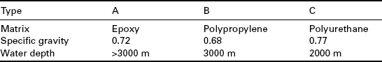
Different matrix materials can be used. Epoxy, polyurethane and polypropylene are all employed, depending on the application and manufacturing method. This type of material is also widely used in other fields such as ballistic protection in the military sector. Some typical properties of such materials are given in Table 10.1. These properties are governed by the nature of the matrix, the grade of the microspheres used and their volume ratio.
In order to improve performance in the buoyancy sector recent developments include the use of macrospheres (diameter from 10 mm up to 150 mm), with skins of polymer or composite materials (Fig. 10.28). Dedicated to deep-sea application, the capacity to withstand the hydrostatic pressure is, in terms of mechanical performance, the main parameter of interest. Micromechanics models have already been proposed to describe the elastic behaviour of this type of material [47–50]. However, at this stage, no satisfactory model has been established which allows the prediction of the collapse pressure of syntactic material under hydrostatic pressure.
Tests have been developed [51] in order to access the hydrostatic compression behaviour of these materials (pressure vs. volume variation). Two typical types of behaviour can be observed. These are related to the relative rigidity of the matrix versus the rigidity of the microspheres (Fig. 10.29).
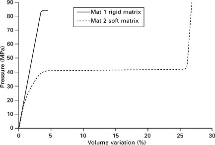
For a microsphere reinforced material with a rigid matrix (e.g. epoxy), quasi-elastic behaviour is observed up to a pressure where sudden global collapse of the material occurs. This pressure is noted as crush pressure and gives the maximum limit for use of the material without any safety factor. The collapse corresponds to the breakdown of the matrix skeleton of the material. For materials with a soft matrix (e.g. polyurethane), the behaviour can be described in three phases. First a quasi-elastic relation between pressure and volume variation is noted. During this phase, damage development has been observed, by means of different techniques (acoustic emission, micro-tomography [52]) from the very beginning of loading. This damage corresponds to the breakage of the weakest microspheres present in the material. It is important to note the Gaussian distribution of the diameters of the microspheres in this grade of material. Taking into account the quasi-constant thickness of the glass skin, the biggest microspheres have the lowest strength. The second phase, here around 40 MPa from 5 to 25% of ΔV/V, corresponds to the total collapse of the microspheres, inducing a densification of the material. In the third phase, the behaviour corresponds to the behaviour of the matrix itself without any fillers. The environmental parameters will affect this behaviour. Temperature will decrease the rigidity of the matrix skeleton, hydrolytic aging will decrease the rigidity of the matrix, first by plasticization and it may then degrade glass microspheres by hydrolysis [53].
There is a need for mechanical models describing the behaviour of this type of material, in order to estimate the long-term behaviour taking into account that the nominal service life of equipment using this material is a minimum of 25 years. This model has to include visco-elastic and damageable behaviour. The relationship between damage and water absorption kinetics has to be established, in order to evaluate the evolution of functional properties correctly.
10.5 Modelling failure
It is not the aim of the present chapter to describe modelling developments, but it is important to note that one of the main aims of a large proportion of the studies described above was to obtain experimental data to compare with numerical model predictions. There are details of modelling results in many of the papers cited. It should be emphasized, however, that while test model correlations for the quasi-static load cases are generally satisfactory there remains much to be done in the area of dynamic simulations.
10.6 Future trends
There is a clear trend in marine structures towards closed mould forming methods, and the traditional image of the materials used in the pleasure boat industry is changing. Higher performance applications, notably in the offshore industry, and the severe environmental conditions of renewable marine energy structures are also pushing material requirements closer to those of aerospace structures. Long-term durability can only be guaranteed when quality controls and certification tests, based on a thorough understanding of the damage and failure mechanisms, are defined and applied. Further research and development efforts are needed to develop the predictive tools needed for these new applications.
10.7 References
[1] Smith, C.S.Design of Marine Structures in Composite Materials. Elsevier, 1990.
[2] ISO/FDIS 12215-5. Hull construction – Scantlings – Part 5: Design pressure for monohulls, design stresses, scantlings determination, 2006.
[3] Baley, C., Cailler, M. Experimental and numerical behaviour of the structure of a 7.7 m sailing boat at sea. Proc. Int. Conf on Nautical Construction with Composite Materials, IFREMER, 1992:423–431.
[4] Manganelli, P., Wilson, P.A. An experimental investigation of slamming on ocean racing yachts. Proc. 15th Chesapeake Sailing Yacht Symposium, 2001.
[5] Martin R., ed. Ageing of Composites. Woodhead Publishing, 2008.
[6] Weitsman, Y. Coupled damage and moisture-transport in fiber-reinforced, polymeric composites. Int Journal of Solids and Structures. 1987; 23(7):1003–1025.
[7] Mercier, J., Bunsell, A., Castaing, P., Renard, J. Characterisation and modelling of aging of composites. Composites Part A. 2008; 39(2):428–438.
[8] Davies, P., Boisseau, A., Choqueuse, D., et al. Long term durability of composites for ocean energy conversion systems. Proc. 2nd International Conference on Ocean Energy (ICOE 2008), 15-17 October, 2008. [Brest, France].
[9] Perrot, Y., Baley, C., Grohens, Y., Davies, P. Damage resistance of composites based on glass fibre reinforced low styrene emission resins for marine applications. Appl Compos Mater. 2007; 14:67–87.
[10] Davies, P., Petton, D. An experimental study of scale effects in marine composites. Composites Part A. 1999; 30(3):267–275.
[11] Wada, A., Kawasaki, T., Minoda, Y., Kataoka, A., Tashiro, S., Fukuda, H. A method to measure shearing modulus of the foamed core for sandwich plates. Comp Struct. 2003; 60(4):385–390.
[12] Gullberg, O., Olsson, K.-A. Design and construction of GRP sandwich ship hulls. Marine Structures. 1990; 3(2):93–109.
[13] Cantwell, W.J., Scudamore, R., Ratcliffe, J., Davies, P. Interfacial fracture in sandwich laminates. Comp Sci and Technology. 1999; 59(14):2079–2085.
[14] Quispitupa, A., Berggreen, C., Carlsson, L.A. On the analysis of a mixed mode bending sandwich specimen for debond fracture characterization. Eng Fract Mech. 2009; 76(4):594–613.
[15] Reichard, R.P.Olsson K.-A., ed. The design of FRP sandwich panels for ships and boat hulls. Proc Sandwich Construction 1. EMAS Publishers, 1989.
[16] Bertelsen, W.D., The Hydromat System: An experimental technique for the static and fatigue testing of sandwich panelsSandwich Constructions 2. London: EMAs, Chameleon Press, 1992.
[17] Ahtonen, P.J., Sikarskie, D.L. An analytical and experimental comparison of orthotropic sandwich panels using the Hydromat Test system. Composites Part B. 1998; 29(6):705–714.
[18] Davies, P., Choqueuse, D., Bigourdan, B. Test-finite element correlations for nonwoven fibre-reinforced composites and sandwich panels. Marine Structures. 1994; 7(2-5):345–363.
[19] Davies, P., Sargent, J. Fracture mechanics tests to characterize bonded glass/epoxy composites: application to strength prediction in structural assemblies. European Structural Integrity Society. 2003; 32:279–292.
[20] McGuinness, G.B., Óbrádaigh, C.M. Development of rheological models for forming flows and picture-frame shear testing of fabric reinforced thermoplastic sheets. Journal of Non-Newtonian Fluid Mechanics. 1997; 73(1-2):1–28.
[21] Olsson, R. Mass criterion for wave controlled impact response of composite plates. Composites Part A. 2000; 31:879–887.
[22] Faltinsen, O.M. Hydroelastic slamming. J. Mar Sci Technol. 2000; 5:49–65.
[23] Baur, P., Roy, A., Casari, P., Choqueuse, D., Davies, P. Structural mechanical testing of a full-size adhesively bonded motorboat. Proc. J. Engineering for the Maritime Environment, I Mech E 218 part M, 2004:259–266.
[24] Hayman, B., Haug, T., valsgard, S. Slamming drop tests on a GRP sandwich hull model. Proc. 2nd Int Conf on Sandwich Construction, EMAs, 1992.
[25] Zhu, L., Faulkner, D. Design pressure for wet-deck structure of twin-hull ships. Proc FAST 95, 1995:257–268.
[26] Jensen, A.E., Havsgard, G.B., Pran, K., Wang, G., Vohra, S.T., Davis, M.A., Dandridge, A. Wet deck slamming experiments with a FRP sandwich panel using a network of 16 fibre optic Bragg grating strain sensors. Composites Part B. 2000; 31:187–198.
[27] Downs-Honey, R., Erdinger, S., Battley, M. Slam testing of sandwich panels. SAMPE Journal. 2006; 42(4):47–55.
[28] Choqueuse, D., Baizeau, R., Davies, P. Experimental studies of impact on marine composites. Proc ICCM12, Paris, 1999.
[29] Baral, N., Cartié, D.D.R., Partridge, I.K., Baley, C., Davies, P. Improved impact performance of marine sandwich panels using through-thickness reinforcement: experimental results. Composites. 2010; 41(2):117–123.
[30] Davies, P., Choqueuse, D., Bigourdan, B., Baral, N., Cartié, D.D.R., Partridge, I.K., Baley, C. Pinned foam core sandwich for improved damage tolerance of racing multi-hull yachts. Proc ICCM17, Edinburgh, 2009.
[31] Davies, P., Choqueuse, D., Bigourdan, B., Gauthier, C., Joannic, R., Parneix, P., L’Hostis, J. Design, manufacture and testing of stiffened panels for marine structures using adhesively bonded pultruded sections. J Eng for the Marine Environment. 2004; 218(M4):227–234.
[32] Partridge, I.K., Cartié, D.D.R., Bonnington, T. Manufacture and performance of Z-pinned composites. In: Advani S., Shonaike G., eds. Advanced Polymeric Materials: Structure-Property Relationships. CRC Press, 2003.
[33] Devaux, H., Casari, P., Choqueuse, D., Davies, P. Compression behaviour and design of very high modulus fibre composites for racing yacht masts. Proceedings JNC14, 14th French Composites Conference, Compiègne, July, 2003.
[34] Ochoaa, O.O., salama, M.M. Offshore composites: transition barriers to an enabling technology. Composites Science and Technology. 2005; 65(15-16):2588–2596.
[35] Bigourdan, B., Chauchot, P., Astrugue, J.C., Micheaux, D., Alary, V., Dilosquer, S., Falcimaigne, J., Rigaill, C., Gérard, P. Composite materials for subsea oil separation. Proc. DOT (Deep Offshore Technology), Marseille, 2003.
[36] Stachiw, J.D. Graphite-Fiber-Reinforced Plastic Pressure Hull Mod 2 for the Advanced unmanned search system (AUSS), 1988. [NOSC TR 1245, Naval ocean Systems Center, San Diego, CA, August].
[37] Davies, P., Choqueuse, D., Riou, L., Warnier, P., Rolin, J.F., Jegou, P., Bigourdan, B., Chauchot, P. Matériaux composites pour véhicule sous-marin 6 000 mètres (Composite materials for an underwater vehicle for 6 000 meters depth). Comptes rendus des 10èmes Journées Nationales sur les Composites. 1996. [Paris 29-31 October].
[38] Lemière, Y.Davies P., Lemoine L., eds. The evolution of composite materials in submarine structures. Proc. Int conf on Nautical Construction with Composite Materials, 1992. [Paris, IFREMER].
[39] Messager, T. Buckling of imperfect laminated cylinders under hydrostatic pressure. Composite Structures. 2001; 53(3):301–307.
[40] Davies, P., Le Flour, D. Long term behavior of fiber reinforced structures for deep sea applications. Paper 21, Proc. Oilfield Engineering with Polymers, London, 2001:255–268.
[41] Hsiao, H.M., Daniel, I.M. Effect of fiber waviness on stiffness and strength reduction of unidirectional composites under compressive loading. Composites Science and Technology. 1996; 56(5):581–593.
[42] Davies, P., Carlsson, L.A. Delamination of composite cylinders. In: Gdoutos E.E., Rajapakse Y., Daniel I., eds. Major Accomplishments in Composite Materials and Sandwich Structures – An Anthology of ONR Sponsored Research. Springer, 2009.
[43] Choqueuse, D., Chauchot, P., Bigourdan, B., Davies, P. Composite pressure vessels for deep sea applications. Proceedings of the ASME 2010 Pressure Vessel and Piping Division Conference, 2010.
[44] Gning, P.B., Tarfaoui, M., Collombet, F., Davies, P. Damage development in thick composite tubes under impact loading and influence on implosion pressure: experimental observations. Composites Part B. 2005; 36(4):306–318.
[45] Davies, P., Riou, L., Mazeas, F., Warnier, P. Thermoplastic composite cylinders for underwater applications. Journal of Thermoplastic Composite Materials. 2005; 18(5):417–431.
[46] Choqueuse, D., Chomard, A., Bucherie, C. Insulation materials for ultra deep sea flow assurance: evaluation of the material properties. OTC 14115, offshore Technology Conference, Houston, TX, 6-9 May, 2002.
[47] Lee, K.J., Westmann, R.A. Elastic properties of hollow-sphere in reinforced composites. Journal of Composite Materials. 1970; 4:242–252.
[48] Christensen, R.M., Lo, K.H. Solutions for effective shear properties in three phase sphere and cylinder models. Journal of the Mechanics and Physics of Solids. 1979; 27:315–330.
[49] Brini, A., Benhamida, A., Dumontet, H., Pradel, F. Ageing damage of immersed syntactic foams under coupled effects of pressure and aqueous corrosion. ICCM-14. 2003. [San Diego, CA, 14-18 July].
[50] Bardella, L., Genna, F. On the elastic behavior of syntactic foams. International Journal of Solids and Structures. 2001; 38:7235–7260.
[51] Choqueuse, D., Davies, P., Perreux, D., Sohier, L., Cognard, J.Y. Mechanical behavior of syntactic foams for deep sea thermally insulated pipeline. Applied Mechanics and Materials. 2010; 24-25:97–102.
[52] Adrien, J., Maire, E., Gimenez, N., Sauvant-Moynot, V. Experimental study of the compression behaviour of syntactic foams by in situ X-ray tomography. Acta Materialia. 2007; 55:1667–1679.
[53] Sauvant-Moynot, V., Gimenez, N., Sautereau, H. Hydrolytic ageing of syntactic foams for thermal insulation in deep water: degradation mechanisms and water uptake model. Journal of Material Science. 2006; 41:4047–4054.