
Manufacturing defects as a cause of failure in polymer matrix composites
Abstract:
This chapter considers the ways in which composite parts can deviate from their intended performance due to issues arising in design and manufacture. It covers the variability of manufacture and the interactions between design, materials and processes, and indicates the level of property reductions that can be experienced. It concludes with future trends in materials and manufacture.
2.1 Introduction and basic requirements
This chapter is devoted to a consideration of the impact of manufacturing defects on failure in polymer matrix composites. To make progress with this we need to start with a set of definitions. Critically a definition of ‘defect’ is needed, but the concept of ‘failure’ also needs some thought. In this chapter ‘defect’ will be defined in the widest possible way as anything that causes a local deviation from an ideal and uniform composite structure. It should be immediately obvious that this definition includes many factors that are part of the design intent, such as tight out-of-plane laminate curvatures, inplane tow curvature due to ideal drape of a woven cloth and ply drops/ply discontinuities. As all these features have a potential impact on mechanical performance, it would be unreasonable to exclude them from any discussion of defects.
There are a great many sources of variability in the materials and processes used in composites manufacture. It is not easy to determine the point at which the acceptable variability becomes a defect and in any case this does depend on both the stressing and the criticality of failure. What would be a severe defect in a safety critical highly stressed aircraft part might not be regarded as a defect at all in an automotive body panel. Conversely cosmetic surface defects would not be acceptable in the body panel but might be irrelevant in the aircraft part. In the broad sense defects are simply defined as out-ofspecification conditions which would include both cosmetic and dimensional errors. These cosmetic and dimensional defects will not be considered here unless they also have an impact on mechanical performance.
The last issue is the baseline mechanical performance against which the ‘defective’ performance is measured. Obtaining good values for many mechanical performance factors in composites is far from easy, especially under compressive loading. It is certainly arguable that the measured test values really represent a lower bound performance due, for example, to difficulties in achieving uniform stress states in test specimens. For the purposes of this work it will generally be assumed that the properties measured in conventional tests and reported in materials data sheets, etc., do represent the maximum available materials properties.
2.2 Sources of variability and defects in composite mouldings
As defects can be generated at any point, it is necessary to consider all stages in the manufacturing processes in order to understand these defects. However, this chapter is limited to as-manufactured defects which will be interpreted as defects that exist prior to the demoulding of components, and thus exclude finishing, machining or in-service damage. For these as-manufactured defects, variability in materials and processing will be critical and it is worthwhile to try to identify some critical areas of this variability. [1]
2.2.1 Sources of variability in materials
For resin infusion and vac-bag/autoclave processing, the sources of variability are listed below. It should be emphasized that other elements of variability could well be important for other processes. It is in general not possible to put these elements of variability and the defects that they give rise to into a specific order of importance. The structural response of a component will derive from the local reaction to local stresses and if that response involves failure, whether and how that failure will propagate through the structure. A defect that might have a trivial impact on performance in one stress state could easily be strength limiting in another.
• mass/unit area reinforcement – global and local
• degree of consolidation in as-purchased reinforcement
• consolidation response to applied pressure
• binder concentration for resin infusion (RI) processes – global and local
• permeability of reinforcement
• wettability of reinforcement
• quality of fibre alignment – global and local
• locking angle for cloth drape
• shear limit for unidirectional prepreg and non-crimp-fabric drape
• ease of wrinkle formation both in-plane and out-of-plane
• resin viscosity and temperature/cure effects on viscosity
• variability of resin composition
• variability in cure kinetics
• shelf life of resin and storage history
• honeycomb core condition and cleanliness
• honeycomb core resistance to crushing
2.2.2 Sources of variability in moulding processes
For resin infusion and vac-bag/autoclave processing, these include:
• operator and supervision skills
• lay-up aids and tools provided
• temperature variations using hot air blowers or hot drape formers for prepreg or bound reinforcement for RI processes
• mould closure issues in resin transfer moulded (RTM) processes
• resin injection pressure in RI processes
• resin injection temperature in RI processes
• resin injection vacuum level in RI processes
• cure cycle variations in temperature and pressure
• temperature variations across part
• interactions between tooling and reinforcement due to differences in coefficient of thermal expansion (CTE)
As noted earlier, it is more useful to consider the impact of irregularities on properties than to try to distinguish between features (arising principally from the part design interacting with the nature of the chosen reinforcements and matrices and the variability in their properties) and defects (arising principally from processing variability and errors in the way that manufacturing processes have been carried out). There is, however, one important reason for attempting to make the distinction and that is that, while defects can be addressed directly by improvements in manufacturing processes, and in principle avoided, it is not possible to eliminate features without wholesale changes to the materials used or to the design of the structure.
Features arising from design decisions may include: residual stresses; ply drops; gaps between plies; fibre waviness in the reinforcement as delivered; additional fibre waviness caused by mapping the chosen reinforcement to the tool; consolidation induced bridging or fibre wrinkling.
Defects arising during manufacture may include: voidage, dry spots and other wet-out issues; delaminations; bridging or fibre wrinkling due to faulty lay-up; fibre waviness due to errors in draping the reinforcement to the tool or due to fibre wash in RI processes. Other defects, including inclusions; ply contamination; errors in ply count, lay-up order or ply orientation; honeycomb core collapse and a range of other core related defects; curing or vacuum errors or bag burst, will not be considered here as they tend to lead to catastrophic losses of properties and the mouldings being total scrap, and must therefore be avoided.
In the next three sections of this chapter the impact of the different ‘defect’ types will be considered. It should be noted that in practice it is common for defective regions in real components to have complex mixtures of different types of ‘defects’ and thus to have more complex impacts on performance. In general terms it is true to say that regions of complex geometry are more likely than simpler regions to contain the sort of features and defects being considered here, and at the same time are likely to carry more complex stress fields and are more difficult to assess through non-destructive testing (NDT). In seeking to eliminate strength reductions due to defects, at least as much emphasis needs to be placed on the design as on the manufacturing activity.
2.3 Impact of residual stresses and geometrical distortions on performance
All matrix resins tend to shrink during the cure cycle due to a mixture of cure shrinkage and thermal shrinkage of the resin when cured at elevated temperature. These shrinkages will lead to stresses at various scales in the composite part [2]. The fibre level stresses are usually ignored, but at the laminate level the coefficient of thermal expansion (CTE) of a ply will be different in plane and out of plane, and for oriented reinforcements will be different in fibre dominated and matrix dominated directions. For a flat laminate of a multi-directional lay-up of unidirectional (UD) reinforcement, each ply will carry tensile stresses transverse to the fibre direction. For laminate made from a 0.90 lay-up of an epoxy matrix UD prepreg cured at 180 °C, the transverse strain from this source can reach up to about 50 MPa (≈0.5% strain). This is a significant proportion of the transverse ply strength. For laminates made from thin plies, this seldom leads to transverse ply cracking at room temperature. However, if multiple plies of the same fibre orientation are used, then transverse cracking becomes a high probability, which can then lead to delaminations and other damage. A lack of balance and symmetry in the laminate can cause laminates moulded on flat tools to warp and twist on cooling due to these CTE mismatches. Even when the laminates are balanced and symmetrical, variability in resin content through thickness due to materials or process variability can lead to non-flat laminates.
When laminates are not flat the greater CTE in the through-thickness direction can no longer be accommodated without geometrical distortion and the part will tend to distort with changes in temperature. For a simple 90 ° bend these difference in CTE tend to produce a reduction in the angle as the part is cooled, a phenomenon known as spring-in. This spring-in distortion can be composed of three elements: the thermal shrinkage through thickness; the cure shrinkage of the resin after the gel point; and distortions caused by interactions between tooling and lay-up if the tool and lay-up have different CTEs, or between the lay-up and any pressure applied to consolidate the part. The thermal shrinkage element is reversible with temperature (thermoelastic) [3] but stresses and distortions caused by the other factors are not affected by changes in temperature (non-thermo-elastic) [4]. As an additional complication moisture pick-up by the part will tend to swell the matrix resin, reducing the level of distortion due to resin shrinkage. Distortions caused by tool or pressure interactions arise from stresses carried by the fibres and cannot be eliminated by moisture uptake. For narrow, thin parts with simple single curvature, these effects generally combine to give a slight closure of the corner angle, typically of around 1 ° on a 90 ° corner for a hot cured UD prepreg part where the fibres run around the corner (although tool interaction effects on very thin laminates can give rise to much larger distortions). For longer parts additional distortions can be seen in terms of twist and a bowing of the nominally flat sections. These distortions are not associated with a significant stress, unless the parts are forced back to nominal dimensions in a later assembly process, and it is usual to try to compensate for them in the tooling design.
As parts become thick or have a significant degree of double curvature or constraint, the residual stresses arising from resin shrinkage become more significant. In the worst case of a resin-rich zone in a fully 3D reinforced structure, the stress can be estimated as ΔT.α.E/(1-2η) [5], where ΔT is the temperature change, α is the CTE, E is the resin’s Young’s modulus and η is the Poisson ratio. Taking reasonable values for a typical hot cured resin system gives a tensile stress in the region of 100 MPa at room temperature. Figure 2.1 shows a section through an approximately 10 mm thick block of orthogonally 3D woven composite illuminated by UV light. The sample had not been subjected to any external loads post manufacture. The resin matrix is slightly fluorescent so that the light squares (approx size 0.9 mm × 0.9 mm) are resin pockets. The bright lines are cracks which have been highlighted using a fluorescent dye penetrant. In each case the cracks are initiated within the resin pockets although they may propagate beyond. It should be noted that no errors were made in the manufacture of this part; although the cracks are clearly defects, they essentially arise from the materials selection process rather than from manufacturing errors.

Regions of constrained geometry such as ‘T’ root sections are also susceptible to increased levels of thermally induced stresses, although seldom giving the total constraint and maximized stresses seen in orthogonally 3D woven parts. In these cases the shrinkage stresses may well be a significant contribution to the matrix stresses, leading to a reduced capacity to withstand applied stresses. The additional constraints on resin shrinkage in areas of out-of-plane fibre wrinkling may also contribute significantly to the strength reductions caused by that class of defect.
2.4 Impact of voidage and delaminations on inplane and out-of-plane properties
Voidage/porosity has long been appreciated as potentially leading to significant loss of those properties which have a major contribution from the resin [6]. These include through-thickness strength, out-of-plane shear strength and compressive strength in 2D reinforced laminated composites. The property loss caused by voidage is not a simple matter of looking at the volume percentage of voids, as the distribution of voids can have a very great impact. The general consensus is that mechanical properties degrade as voidage increases, initially that reduction is slow, a few percentage drop in interlaminar shear strength for each percentage increase in voidage up to perhaps 4 or 5% voidage [7]. This region is associated with a more or less uniform distribution of small voids of roughly circular cross-section. As voidage increases beyond about 5%, the voids tend to become more localized at ply interfaces and to become of more irregular cross-sections. This latter sort of voidage is much more damaging to properties and the rate of decay in properties will increase rapidly beyond the point at which the morphology of the voidage changes from small, circular and well distributed to localized and irregular. Whilst these general comments would be expected to be applicable to any laminated structures, the rate at which properties degrade and the point at which that degradation increases is not predictable from first principles for any given reinforcement/matrix pair. For critical components it is usual to stipulate a maximum permissible voidage of perhaps 2% as a quality control limit. However, it is actually the void morphology that controls the acceptability of the voids and not the level of voidage in percentage terms. Measurements of through-thickness strength by loading a corner piece (100 mm arm length, approx. 14 mm thickness) as shown in Fig. 2.2 showed that a reduction in strength of more than 50% could be experienced due to a void content of less than 0.5% [8].

In this case [8] the general laminate quality was actually very good with almost no voidage being visible, apart from a series of small voids in a localized patch at a single ply interface. This series of voids coalesced and formed a delamination under load, leading to a very significant loss of strength. We can then treat manufacturing induced delaminations as a special case of localized voidage. Delaminations will be very damaging to through-thickness and out-of-plane shear strength and would be expected to lead to a significant loss of compressive strength and buckling resistance, but to have little impact on in-plane tensile strength.
Perhaps unsurprisingly, the conclusion is that to gain a good understanding of the likely impact of voidage (and by inference delaminations) we need to know the number of voids, their morphology and distribution and the relationship between this distribution and the level and direction of relevant stresses. We seldom have all of this information and instead use the simple, but potentially inadequate, assumption that limiting the overall voidage level is sufficient to ensure that matrix dominated strength properties will be adequate.
2.5 Impact of misaligned, wavy and wrinkled reinforcements on in-plane and out-of-plane properties
This is a complex area and we need to start from first principles and work up from there. The first question is really ‘what do we mean by misaligned?’. For a flat laminate we can be completely unambiguous about the intended and actual fibre direction datum and thus about the accuracy of alignment. For components such as those shown in Fig. 2.3 (duct component in Fig. 2.3(b) is 320 mm long) there is no intuitively obvious fibre direction datum and we require local frames of reference against which we can define the correct fibre direction and thus give an indication of fibre misalignment.

Fibre misalignment can then be defined as a deviation between the nominal and actual fibre direction. This misalignment can be in-plane, out-of-plane or a combination of both. There is no universally accepted terminology to describe this misalignment, but for the sake of clarity in this chapter inplane misalignment will be described as fibre waviness and out-of-plane misalignment as fibre wrinkling.
Assuming that we can define an adequate fibre direction datum at any point, it is next necessary to look at the mechanisms by which fibre misalignments can be generated. As before it is useful to consider both unavoidable features and avoidable defects separately.
Unavoidable factors in continuous fibre composites
• As-delivered UD tows may not be entirely straight
• UD prepreg usually contains in-plane wavy fibres
• Woven cloth always contains crimped (i.e. wrinkled fibres)
• Non-crimped fabrics normally exhibit some distortion of the tows due to the stitch or binder yarn fibres
• When forming any reinforcement around an out-of-plane radius, additional waviness will be generated
• When forming any reinforcement around an in-plane radius, additional waviness or wrinkling will be generated
Avoidable defects in continuous fibre composites
2.5.1 Unavoidable factors
The key to understanding many of the unavoidable features is to examine the nature of the tows of fibre. A tow consists of thousands of very thin (typically <10 μm) fibres, which may be held lightly together with a small amount of size or binder, or be completely dry. To a first approximation the fibres individually have no resistance to bending or buckling under load, even under their own weight let alone under any externally imposed forces. Bending the tows will generate a compressive stress on the inside radius which will tend to buckle the fibres and generate misalignment, which may not be recovered when the tow as a whole is straightened out. Any snagging of fibres in the tow during processing produces similar effects and handling dry fibre tows needs to be done with great care to avoid introducing defects.
As-delivered UD tows have usually been wound onto a small (<100 mm) diameter tube, leading to the sort of localized fibre misalignment noted above. Any localized misalignment introduced at this stage will tend to carry through to the next process step, whether that is the manufacture of UD prepreg or the weaving of a cloth.
UD prepreg usually contains in-plane wavy fibres as can be seen in Fig. 2.4. Both samples are approximately 6 mm long in the fibre direction. Both a generalised waviness (e.g. at Fig 2.4(a)) and localized defects (e.g. at Fig. 2.4(b)) can be seen in the prepreg [9]. The level of generalized fibre waviness for this prepreg is essentially equivalent to what would be expected due to the prepreg being wound on to a drum for delivery, leading to the compressive collapse of the fibres on the inner radius. The level of generalized misalignment in the prepreg shown is a maximum of about 3.8 °, with a wavelength of a few mm. When this prepreg is laid up on to a curved surface, the inner surface is once more put under a compressive stress and this has the effect of increasing the misalignment without significantly impacting on the wavelength. The misalignment can be visualized by polishing sections through corner regions as the reflectivity of the areas where the fibres are in the plane of the section is very different from that of the regions of more misaligned fibre (see Fig. 2.5), approximately 2 mm thick (8 × 0.25 mm plies).


The laminate has 8 plies (2 mm total laminate thickness) and each ply shows alternating light and dark regions which indicate the changing fibre direction due to the waviness in the fibres for this laminate moulded on a 10 mm internal radius tool. The fibre misalignment in this case is principally in the plane of the ply as a result of an out-of-plane curvature in the tow. The measurements of through-thickness strength measured as shown in Fig. 2.2 accommodate this level of misalignment as a feature of the laminate’s internal structure. Through-thickness strength is notoriously difficult to measure, but strength measured in corner regions seems not to vary greatly from strength measured on flat laminates. This may indicate that the level of in-plane fibre waviness seen here does not impact greatly on through-thickness strength.
If the tows are curved in the plane, as they might be in a tow steered laminate, a greater impact on fibre alignment will be expected as the tow width is generally 10–20 × the ply thickness and can be much more if the tows have been spread.
Figure 2.6 shows a laminate made from a tow steered preform where approximately 2.5 mm wide tows of dry fibre have been steered in curved paths and stitched to a backing fabric with epoxy-soluble stitches and then resin film infused and cured. The fibres show up as bright lines and the resin as dark areas. The inside surface of each tow can be seen to be very wavy, where the fibres in the tow have buckled to give both in-plane and out-ofplane misalignment.

The comments above apply specifically to laminates made with tows of fibre that do not have any inherent out-of-plane fibre alignment, such as UD prepregs or non-crimp fabrics. For woven cloths and braids there will be some out-of-plane misalignment due to the weaving process. This misalignment is innate to the material and is a feature rather than a defect. Woven cloth is principally used where there is a need to match the reinforcement to complex geometrical features by the process of distorting the cloth known as drape. The drape process can also generate curved fibre paths so the impact on tow level misalignment shown in Fig. 2.6 will also be seen in draped woven cloths where fibre paths are curved (see Fig. 2.7 [10] (tow width approximately 2 mm).

2.7 The impact of woven cloth drape on tow geometry [10].
Ply drops will generate localized fibre wrinkling as the fibres are deformed out of plane to match the ply edges of the dropped plies. This can generate significant – if highly localized – fibre misalignment and initiate delaminations under in-plane tensile loading.
It should be clear from the discussion above that a typical laminate is made from tows of fibre that are not ideally straight, these are then transformed into semi-finished products such as cloths and prepregs which contain higher levels of misalignment and then converted into products which contain additional levels of local misalignment due to the part geometry and forming routes. It must be stressed that these misalignments are largely unavoidable, as determined by the particular material and part geometry used.
2.5.2 Avoidable defects in continuous fibre composites
The distinctions between features and defects are not always entirely clear, but in general defects involve a localization of the misalignment and a deviation from the ideal geometry or internal laminate structure.
The simplest error might be seen as a defect in lay-up as shown in Fig. 2.8 [10]. When we try to lay a sheet of UD prepreg onto a curved surface a mismatch between the prepreg and the surface, become apparent as the area that is in contact with the tool is increased. The process shown schematically in Fig. 2.8 can be used to mimic that mismatch. If a UD ply is cut to the shape in Fig. 2.8(a) with a slight offset at the ply mid length and that ply is then laid down on a flat surface as shown in Fig. 2.8(b) so that the offset is laid to a straight edge an excess length is generated at the left side of the ply. When the ply is pushed down on to the flat surface an area of wavy fibre is formed in the region of misaligned fibre shown in Fig. 2.8(c). The level of fibre waviness that can be generated by a 2 ° offset is shown in Fig. 2.9. A region of gross misalignment is formed (a 40 ° fibre misalignment) from a minor lay-up misalignment of 2 °.

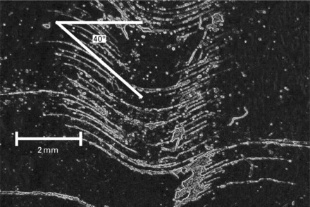
Equally large-scale misalignments may be formed as reinforcements are pressed into tools, especially by mould closure forces in resin transfer moulded (RTM) components, or by the way in which preforms are manufactured for RTM moulding. Figure 2.10 (sample 30 mm wide 150 mm long) shows the level of misalignment that can be generated during mould closure. Fig. 2.11 shows fibre wrinkling generated during dry fibre preforming for a 6 mm thick section cut from a production component. Figure 2.12 shows fibre wrinkling in UD prepreg quasi-isotropic corner region probably caused by the action of the autoclave pressure on the lay-up, image size is approx. 10 mm wide × 8 mm high.

2.10 Gross fibre misalignment caused by mould loading forces – the white line shows the tow trajectory around the corner.


Fibre wash in RTM is caused by the action of the resin flow pushing the reinforcement from its ideal position. Depending on the details of the resin porting, the reinforcement type and volume fraction, etc., a range of defect types can be generated, from surface resin-rich zones associated with fibre wrinkling such as shown in Fig. 2.11, to severe localized fibre waviness as shown in Fig. 2.10.
Consolidation on radii in autoclave moulding tends to lead to bridging (thickening of the laminate) in internal radii, and fibre waviness and wrinkling on external radii as the consolidation of the laminate leads to excess length in the outermost layers of prepreg.
2.5.3 Impact of fibre misalignment defects on strength
It must be noted that all of the figures given here for the effects of misalignment on strength are related to the specific materials, lay-up and defects under consideration. While they may be typical for these sorts of defects they cannot be used to predict the performance of other materials or processes. They are perhaps better used to identify the sorts of defects we must aim to avoid rather than the level of strength knockdown that may have to be tolerated.
The defects shown in Fig. 2.9 (arising as shown in Fig. 2.8) have been examined as follows. An eight-ply 2 mm thick laminate was made up with four plies undeformed and four plies deformed as shown in Fig. 2.8. The results of testing these samples in flexure (with the defects on both tension and compression faces) are shown in Fig. 2.13. The increase in thickness in the misoriented region was taken as a marker for the severity of the waviness/wrinkling (generally increasing from point 1 to 5 in Fig. 2.8(c)) and plotted against the reduction in baseline strength for a nominally ideal laminate. There was, as might be expected, a very significant reduction in strength as the severity of the defect increased. The tolerance on the laminate thickness for this sort of laminate is likely to be ±5%, so that in principle a component with a more severe wrinkle could be identified and eliminated from the population. However, an inspection of the data shows that even very small thickness increases can be associated with significant loss of strength, making inspection more problematical.

The majority of work on the impact of defects on strength has been carried out on flat laminates with simulated defects with much less work being carried out on samples extracted from production components. As noted above, fibre wrinkling defects would be expected to be associated with changes in thickness for processes using single sided tooling, giving some prospect of a simple, if not totally effective, non-destructive inspection (NDI) approach to their control. For fully tooled processes such as RTM this is not possible and even severe internal defects may not be obvious at the surface. For this reason it is useful to concentrate on simulated defects in RTM mouldings.
A 6-ply 5-harness satin carbon cloth RTM preform was made with a simulated defect or feature of a lateral displacement of tows to give an in-plane fibre misorientation of about 30 ° in the nominally 0 ° fibres (e.g. due to drape run-out), on plies 2, 4 and 6 as shown in Fig. 2.14 [11]. The compression strength at failure was reduced by 25% compared to the baseline strength. The first damage (delamination) was seen at 65% of baseline compressive strength (the baseline is linear to failure with no evidence of damage before failure).

A 6-ply 5-harness satin carbon cloth RTM preform was made with a simulated defect of through thickness out-of-plane reinforcement wrinkling as shown in Fig. 2.15 (cross-section through 2 mm thick laminate gauge length redrawn from micrograph to improve clarity). All six plies were affected by the defect and the maximum out-of-plane fibre misalignment in each sample tested was between 18 and 29 °. In the worst case a complex failure initiated at 28% of the baseline compressive strength. The multiple regions of wrinkled fibre can act as ‘hinges’ to allow lateral displacement under compressive loads [11].

A 2 mm thick 6 ply 5 harness satin carbon cloth RTM preform was made with a simulated defect of a resin-rich surface zone generated by an out-ofplane distortion of the surface plies on one surface only. This generated a localized resin-rich zone on one surface and samples were tested in tension. A delamination was initiated at the interface between deformed and undeformed plies at 48% of the baseline tensile strength and complete failure occurred at 68% of the baseline tensile strength (see Fig. 2.16) [11].

The sample shown in Fig. 2.11 was cut from a carbon epoxy production RTM part. For this component differences in mould loading and consolidation techniques give two sets of parts. One had uniform fibre packing, the other had a resin-rich surface with undulations in the surface of the reinforcement as shown in Fig. 2.11. The flexural strength of the resin-rich samples was 72% of that for the samples with uniform fibre packing with initial damage by delamination.
Returning to the corner samples shown in Fig. 2.12, these were cut from production parts and loaded as shown in Fig. 2.2 to measure the throughthickness tensile strength. There were three distinct sets of results in this testing. The first were ‘good’ samples where there was no localized voidage or deviation from the expected ply trajectory around the corner. These had strengths over 50 MPa and failed by a single line of failure at a position close to the peak transverse tensile stress. The second group exhibited wrinkled plies and first failure occurred at the position of the wrinkle and remote from the position of peak transverse tensile stress (see Fig. 2.17) [8].

In addition to the change in the point at which failure initiates, the failure propagation is also different from the baseline case. The failure propagates by multiple delaminations initiating and growing for short distances before another delamination is initiated at a different ply interface. There is a general decrease in strength as the misalignment increases, up to a 50% reduction in through-thickness strength above a 20 ° misalignment. For the third set of results, as noted earlier, a similar or even greater level of strength reduction could be produced by the presence of voids concentrated at one interface between plies even when the fibre alignment was ideal.
It has been pointed out earlier that the majority of real components incorporate ply terminations within the structure and that these terminations, or ply drops, can lead to reductions in strength. The reductions in strength are associated with delaminations originating from the cut ply ends and the small resin-rich zones at the ends of the cut plies. Good practice for the design of thickness transition regions is generally quite well understood. Positive factors include: ensuring that ply drops are internal to the laminate, rather than being surface mounted, that multiple ply drops do not occur at the same place in the structure or in corner regions or in other regions of high through thickness or shear stress and so on. It has been noted, however, that poorly made ply drop regions, where the consolidation of the ply drop region leads to additional fibre wrinkling, can be more damaging to properties than a set of well-made external ply drops [12]. However, even assuming an ideal manufacture, the ply drops will act as regions where additional non-fibre-dominated stresses will be present and will generate delaminations under load that can propagate to failure in static or fatigue loading.
Work has been reported on trying to eliminate the impact of ply drops by chamfering the cut edge of the ply to minimize its thickness and hence the size of the resin-rich zone and the stiffness mismatch at the ply end. For glass fibre unidirectional laminates the translucency of the laminate allows the onset of a delamination to be observed directly. A direct comparison between UD glass laminates with chamfered and unchamfered ply drops showed a significant improvement in strength for the chamfered ply laminates, in both tension and compression under static and fatigue loading. These observations reopen the issue of the distinctions between defects and features. It would normally be assumed that the reduction in strength due to premature failure initiated by delaminations at ply drops would have to be accepted as a feature of the design (so long as no additional wrinkling was present). In the case reported above, the tensile strength with unchamfered plies was 1090 MPa and was 1400 MPa with chamfered plies [13]. The compressive strength with unchamfered plies was 636 MPa and with chamfered plies was 1130 MPa. These chamfered ply strength values are actually higher than the manufacturer’s quoted tensile and compressive strength for the prepreg used. When the option of eliminating the premature ply drop failure initiation by ply chamfering is available, and has been demonstrated to be effective for a particular material, it becomes arguable that failure at a ply drop is the result of a defect rather than a feature, as it is now avoidable.
2.6 Approaches to minimize the impact of manufacturing defects
2.6.1 Designing out ‘defects’
As noted above, there are many features that can impact on mechanical performance that arise directly or indirectly from the design process. For example, a decision to use a 5 mm internal corner radius on a tool to make a 5 mm thick moulding would guarantee a defective part as the nominal geometry, whilst geometrically feasible, is simply not practically possible. As the thickness drops in proportion to the radius, a good quality will steadily become easier to achieve; however, a 5 mm internal radius is still quite small in absolute terms and rather difficult to lay prepreg into accurately. To get a good reproducible quality by hand lay-up of unidirectional prepreg, a minimum corner radius of perhaps 10 mm would be a better design with regard to manufacturability and moulded quality. The larger corner radius will be less likely to be bridged, less likely to be seriously voided and will definitely have lower levels of fibre waviness induced by the curvature of the prepreg. A part of the design process in this case would be the selection of the specific grade of prepreg to be used. Selecting a heavier grade of prepreg would reduce the number of plies and thus positively impact on labour costs; but the level of fibre waviness induced by the curvature would be increased, and the difficulty of achieving a high quality lay-up may also be increased compared to that for the thinner prepreg.
Equally, for a part that has significant double curvature and requires the use of an extensively draped reinforcement, the selection in the design process of a woven reinforcement with a wide tow rather than a narrow tow will increase the level of fibre wrinkling as those tows are distorted in the drape process. It is also worth noting here that for any geometry that can be draped with a piece of woven cloth there are generally multiple pathways by which that drape can be achieved [14]. Even though the initial orientation of the cloth to the tool may be identical, each pathway to the final draped geometry will generate a different set of local fibre orientations and characteristic features and ‘defects’. Different pathways will also require more or less skill from the operator, with some pathways being much more likely than others to generate defects.
A detailed examination of drape processes and the characteristics of different materials is beyond the scope of this chapter, but in view of the potential impacts on quality and performance, the examination of the details of lay-up and manufacture must form part of the design process. Features such as ply drops are often designed by reference to company design manuals principally focused on avoiding interaction between one ply drop and the next. In regions of rapidly changing or complex stresses, it may be better to design the ply drops to avoid placing them in regions of high shear or through-thickness tensile stress.
In conclusion, there are very many features of a composite part that can have the same impacts as defects and lead to reductions in performance. These features must be accommodated by integrating materials’ response and manufacturing considerations into the design process.
2.6.2 Controlling out defects
Assuming that the design process has output a design that meets the sort of requirements noted above and that the impacts of those design features on mechanical performance have been properly accounted for in stress analysis, the manufacturing task is simply to ensure that the design intent is carried through into production. There is a rather gray area between design and manufacture in much industrial practice.
Generating unambiguous manufacturing instruction sets and validating the reliability and reproducibility of these in a production environment is a critical part of the product development process. A logical design and manufacture cycle might position this activity as the final element of the design phase. The manufacturing role would then be simply to implement those instruction sets with suitable inspection and control steps. In this view of the design and development process, accommodating materials variability falls into the design area and accommodating process variability falls into the manufacturing area. It is more common in an industrial setting to hand over from a design to a manufacturing lead prior to the generation of unambiguous manufacturing instruction sets, so that the responsibility for all aspects of quality, control and variability fall into the manufacturing area. The problem with this is that the unambiguous manufacturing instruction sets that are generated may not then be checked against all the details of the design intent. The phrase ‘unambiguous manufacturing instruction sets’ has been used repeatedly here. There can be no apologies for this: unless ambiguity is eliminated and validated processes are used throughout, the probability of the manufacturing process drifting away from the design intent and drifting into a lack of control is unacceptably high.
Probably the most critical step in the whole product development cycle is the transfer between design and manufacturing responsibility. Ideally the transfer is gradual; as the details of the design are clarified and tested against materials and process capabilities and variability, those details can move across into the manufacturing arena – until transfer is complete with a reliable production system in place. The steps at which control is required will emerge during the design process, during the process of generating unambiguous manufacturing instruction sets, during the manufacture of pre-production prototypes and in the manufacture of early production models. It is good practice to capture quality information relating to both product variability and defects in a well-structured and searchable database, from the very start of the transfer from design into production. Design has the information on regions of importance from a structural viewpoint, and manufacture has the information on process capability and regions of potential deviations from ideal manufacture. only by combining the two sorts of data can the right controls be put in place.
2.6.3 In-process inspection
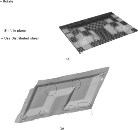
As the automation of the composites production processes develops, it would be expected that the process control and inspection would be an integral part of the automated machinery. However, for the foreseeable future many of the quality critical steps will still be carried out by manual operations. Historically the controls on the lay-up element of manufacture have been limited to the use of manufacturing instructions and sign-off sheets to ensure that tasks have been completed and that inspection has been carried out. The only approach that has been widely used has been visual inspection – an inspector (or more commonly the operator) simply examines the part in production to check that it ‘looks OK’. This will catch many defects but is not adequate to catch developing geometrical problems such as minor bridging that may develop with subsequent plies into a serious defect. there is currently no fully developed system that can identify developing geometrical problems during lay-up. there are indications that surface scanning techniques can be combined with a thorough understanding of manufacturing processes to give the information needed, although these still need significant development to become integrated into the production environment, (see the 600 mm × 400 mm sandwich panel inspection illustrated in Fig. 2.18.
2.7 Future trends
2.7.1 Design of reinforcements and matrices that are less prone to sensitive defects
In an ideal world the reinforcements used would be designed to be exactly suited to the manufacturing processes that are available to give robust processing. Current woven reinforcements are well aligned to manual layup processes but are not well-suited to automated manufacturing processes such as stamp forming or vacuum forming. the principal reason for this lies in the cloth deformation mode. the single deformation mode available in woven cloth (scissoring shear) gives a fully reversible deformation mode that allows for manual handling and repositioning without damage to the reinforcement. However, if the fully versatile manual handling is replaced by simple mechanical forming then more deformation modes are required (cf. sheet metal forming). Non-crimp fabrics can have more deformation modes (scissoring shear or transverse stretching + inter-tow shear, depending on fabric structure) as can unidirectional prepreg (transverse stretching + in-plane shear), and both perform better than conventional woven cloth in automated forming [15]. However, both these reinforcements are generally made from inextensible continuous fibre tows. Extensibility needs to be incorporated into the tow to provide more deformation modes to permit forming of fully clamped sheets and open out the manufacturing options. Various options have been tried in this area [16] and more work is needed to balance manufacturing and performance requirements.
Current matrices contribute to defects through cure shrinkage and high thermal expansion coefficients. It may well be that these properties are inherent in the chemistry used, but any improvements in these areas would be of significant benefit with regard to performance. Equally, the use of a single matrix at all points in the laminate is not ideal as the balance of say stiffness and fracture toughness should perhaps be different within the tow, between the tows and at ply drops and other discontinuities. Having said that, the development of such complex matrices is perhaps a long-term aim and the short-term targets should be to understand the current matrices to maximize process robustness.
2.7.2 Managing variability in materials and processing
Studies of variability in unidirectional prepreg materials have shown that this variability can have a real impact on process reliability and on part performance [1, 9, 10]. other reinforcement forms may be less susceptible to variability, but the data available to support that assumption are insufficient. Unfortunately, there is no realistic way for the average manufacturer of composite parts to limit this variability from their material suppliers. It is well worth keeping track of the variability in incoming materials to identify any long-term trends and to trap any marginally compliant material that might cause production problems. the in-roll variability can be as high as the roll-to-roll variability, making a material selection approach to narrowing the variability generally infeasible. the main impacts on in-process variability are probably in the lay-up stage and are dealt with in Section 2.6. Variability in the cure process seems not to be a major factor in product quality, although the impact of variability in out-time can be quite different from one resin system to the next, with some resins being very sensitive to storage life and others having very wide process windows over a very long storage life. It is clearly preferable to have matrices with the latter characteristic, although this will only be one factor among many in the selection of a matrix, and unfortunately is seldom taken as a critical factor.
The current status is that we are trying to manage the variability in materials and manufacturing processes without many of the tools needed to support this activity. the history of advanced composites to date has largely been about the targeted development of material forms that focus on mechanical performance as measured on carefully selected and defect-free flat laminates. It can be shown that the mechanical performance can rapidly be degraded by deviations from the ideal composite structure arising from both design decisions and manufacturing errors. We need to rebalance the development targets to focus on improving the performance of real complex parts, and away from flat laminates.
2.8 References
1. Potter, K. Understanding the origins of defects and variability in composites manufacturing. In 17th International Conference on Composite Materials, 27-31 July. Edinburgh International Convention Centre (ICCM 17), Edinburgh, UK, 2009.
2. Wisnom, M.R., Gigliotti, M., Ersoy, N., Campbell, M., Potter, K.D. Mechanisms generating residual stresses and distortion during manufacture of polymer-matrix composite structures. Composites: Part A. 2006; 37:522–529.
3. Bogetti, T.A., Gillespie, J.W. Process-induced stress and deformation in thick-section thermoset composite laminates. J Compos Mater. 1992; 26:626–659.
4. Twigg, G., Poursartip, A., Fernlund, G. Tool-part interaction in composites processing. Part I: experimental investigation and analytical model. Composites Part A: Applied Science and Manufacturing. 2004; 35:121–133.
5. Roark, R.J., Young, W.C.Formulas for Stress and Strain. Maidenhead: McGraw-Hill International, 2001.
6. Judd, N.C.W., Wright, W.W. Voids and their effects on the mechanical properties of composites – an appraisal. SAMPE Journal. 1978; 14:10–14.
7. Ghiorse, S.R. Effect of void content on the mechanical properties of carbon/epoxy laminates. SAMPE Quarterly. 1993; 24:54–59.
8. Rashid, A.Investigation of through-thickness assembly stresses in composite wing spars. UK: University of Bristol, 2007. [PhD thesis, October].
9. Potter, K., Langer, C., Hodgkiss, B., Lamb, S. Sources of variability in uncured aerospace grade unidirectional carbon fibre epoxy preimpregnate. Composites Part A: Applied Science and Manufacturing. 2007; 38:905–916.
10. Potter, K., Khan, B., Wisnom, M., Bell, T., Stevens, J. Variability, fibre waviness and misalignment in the determination of the properties of composite materials and structures. Composites Part A: Applied Science and Manufacturing. 2008; 39:1343–1354.
11. Khan, B., Potter, K., Wisnom, M.R. Simulation of process induced defects in resin transfer moulded woven carbon fibre laminates and their effect on mechanical behaviour. In 8th International Conference on Flow Processes in Composite Materials (FPCM8), 2006. [Douai, France].
12. Hart-Smith, L.J. Designing with advanced fibrous composites. Douglas paper 8011, Presented to Australian Bicentennial International Congress on Mechanical Engineering, Brisbane, May, 1988.
13. Khan, B., Potter, K., Wisnom, M.R. Suppression of delamination at ply drops in tapered composites by ply chamfering. Journal of Composite Materials. 2006; 40:157–174.
14. Wang, J., Paton, R., Page, J.R. The draping of woven fabric preforms and prepregs for production of polymer composite components. Composites Part A: Applied Science and Manufacturing. 1999; 30:757–765.
15. Potter, K. Beyond the pin-jointed net: maximising the deformability of aligned continuous fibre reinforcements. Composites Part A: Applied Science and Manufacturing. 2002; 33:677–686.
16. Taketa, I., Sato, N., Kitano, A., Nishikawa, M., Okabe, T. Enhancement of strength and uniformity in unidirectionally arrayed chopped strands with angled slits. Composites Part A. Applied Science and Manufacturing. 2010; 41:1639–1646.