Considerations of failure mechanisms in polymer matrix composites in the design of aerospace structures
Abstract:
When designing with composites, it is important to consider their potential failure modes, especially delamination, when performing trade studies for different structural configurations and manufacturing approaches. Additionally, temperature extremes, moisture, and a variety of fluids that are common to aircraft fabrication and maintenance and prevention of damage from these are necessary in materials selection, design, and qualification. Other design considerations are the effects of fire, lightning, and electromagnetic radiation. Because of the wide variety of design drivers, it is imperative to ensure that there is a clear understanding of failure modes to enable designers to take advantage of composite materials’ anisotropy without creating unwanted stress concentrations and/or failure modes that could compromise structural integrity. This chapter provides a review of the various failure mechanisms in composites that must be taken into account in order to design and build durable and safe aircraft composite structures.
8.1 Introduction
Composite materials have been desired for use in aerospace structures since their inception due to their potential for reducing overall system weight compared with metallic structures. However, unlike metals, composites are laminated structures meaning that, not only do they require different design, fabrication, and inspection methods than metals, but they also possess different failure modes. Most important is the failure mode of delamination in which failure occurs between adjacent plies and proceeds to grow between the plies. Delaminations, although they may not involve significant fiber damage (though often this is not the case), compromise in-plane mechanical properties by reducing the stiffness and stability of the composite structure.
Interlaminar failures may be initiated by impact, fatigue, or by stresses from pre-existing notches or holes. When designing with composites, it is important to consider these potential failure modes when performing trade studies for different structural configurations and manufacturing approaches. Because composites are anisotropic, they may be tailored to have different properties in different directions, depending on the desired structural features. Getting the right balance between a tailored design that minimizes stress concentrations and weight and a design that is relatively simple and inexpensive to manufacture and maintain should be the chief goal in the design, and composites are no exception.
Although composite materials do not corrode in the way that metals do, they may be susceptible to fluid exposure or to oxidation at elevated temperatures. For example, nearly all structural polymers suitable for aerospace absorb a non-trivial amount of moisture, which plasticizes the matrix resin. The moisture fills up the free volume within the polymer and eases relative chain-to-chain motion such that the resin modulus is reduced, especially at elevated temperatures. Solvent resistance is also important as aerospace composites are exposed to paint strippers, hydraulic fluids, anti-icing fluids, etc. It is important to characterize material behavior when exposed to these fluids to ensure that any property changes are accounted for during design.
Other design considerations are the effects of fire, lightning, and electromagnetic radiation. Fire safety is primarily of concern for interior structures, though the primary structure also must meet certain fire-safety requirements. Lightning strike is of much greater concern with composites because, unlike metals such as aluminum, they are not highly electrically conductive such that additional materials need to be added to composite structures to enable them to withstand a lightning strike. In the absence of these additional materials, composite matrices may burn or be vaporized locally due to a lightning strike and holes may be present in the structure, which is particularly a problem for wings in which flammable fuel is present. Electromagnetic radiation is generally not thought to affect composite mechanical properties, but shielding from such radiation is necessary to protect passengers and electronic systems within an aircraft to ensure the safety of both.
The above paragraphs outline some of the design considerations related to possible failure modes within polymer matrix composites (PMCs). Because PMCs are anisotropic, as previously noted, it is imperative to ensure that there is a clear understanding of failure modes to enable designers to take advantage of the materials’ anisotropy without creating unwanted stress concentrations and/or failure modes that could compromise structural integrity. This chapter will discuss these details and some others in greater detail to help the reader gain a greater appreciation for the level of detail required in the proper design of aerospace structures. The main focus area of the discussion below will be on subsonic aircraft structures, though some mention of other types of aerospace vehicles will necessarily also be included.
8.2 Design considerations
Composite materials are sought out for their high specific strength and stiffness relative to metals. Despite the differences in properties, handling, manufacturing, etc., the main design approach (note, this means the general design methodology and not the specific design result) used with composites closely follows that used for metals. Stresses calculated for aerodynamic loading, flutter, vibration, etc. are generally the same for a composite as for a metallic structure as these are mainly related to the shape of the aircraft structure and not its content. What differs is the design approach and options available to the designer when composites are introduced into the toolset available to the designer.
8.3 Structural considerations
General design parameters related to strength and stiffness requirements of the structural elements that comprise an aerospace structure are largely based on known or calculated static and dynamic loads for sizing a vehicle. In order to certify an aircraft, if must meet Federal Aviation Administration (FAA) and/or other necessary regulatory requirements. The structural requirements that will be discussed here are outlined in Federal Aviation Regulations (FAR) Part 25 Structural Design Criteria [1]. These regulations cover all of the structural issues that will be discussed in this chapter, though they are not all specific to composite materials. Elements of failure modes in composite materials that are related to meeting the FAR will be discussed below.
Some of the critical FAR sections affecting composite structural design are:
• Lightning strike (FAR 25.581).
• Ultraviolet light (i.e. sunlight), and impact from rain and hail (FAR 25.609).
• Impact damage from a burst rotor (FARs 25.361, 25.362, 25.365, and 25.903(d)).
• Impact from bird strikes (FARs 25.571, 25.631, 25.775).
• Acoustic (sonic) loadings (FAR 25.571).
• Impact from a broken engine fan blade (e.g. ‘bladeout’) and windmilling of engine rotors (FARs 25.361, 25.362, 25.365, 25.901(c), 25.903(c), 25.903(d), 25.1309).
8.3.1 Determination and design considerations for in-flight loads
Numerical simulations of actual flight loads are performed during the design of aircraft structures. This allows for an initial sizing of the aircraft and its major subcomponents like the wings and fuselage. These numerical models have been developed over many years using both in-flight and wind-tunnel test data to refine model fidelity. An early example of this is the design of the Lockheed L-1011 [2] where there was a general approach of first establishing external loads and using these to determine structural design criteria to enable the definition of loads and loading spectra against which a design may be validated. The use of this methodology combined with a testing program that works from testing small coupons to successively larger test articles and subcomponents is called the building-block approach and is still the foundation of aircraft design and development [3].
In establishing external loads, the following must be considered:
1. Aerodynamic lift loads and wind-tunnel pressure tests to determine the principal structural loads that can generally be validated through static and cyclic fatigue testing.
2. Dynamic loads such as due to flutter, turbulence, and engine vibration that are used to size locations where these loads are most prevalent, such as wing-to-body joins, engine pylons, and flight-control surfaces.
3. Takeoff and landing loads are handled mainly by the landing gear, which is largely a metallic structure. The way that these loads are transferred into the airframe will guide the design of structures that interface with the landing gear.
4. Impact loads such as from bird strikes, hail, dust, sand, and runway debris must also be considered. These will be discussed in detail in Section 8.3.3.
In all of these cases, wherever loads are transferred from one substructure to another or where attachments are present, the effects of fasteners and joint design are paramount. Local stress concentrations due to the presence of fasteners and the effects of the fastener or bolt loads on the holes created for inserting the fasteners must be considered in the design of these details.
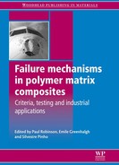
General structural loads may be handled using basic composite material laminate theory from a large number of sources (e.g. Refs [4]–[10]). These tools, combined with numerical simulations like finite-element methods determine the basic laminated structures needed for meeting design loads. The basic sizing of different components and subcomponents is carried out using this methodology and, aside from the use of laminate theory, this process is essentially the same as that used in the design of aerospace structures using isotropic metals. An example of this is a wing up-bending test that is used in the certification of commercial aircraft as shown in Fig. 8.1 that is required independent of the materials used to fabricate the structure.
8.1 Ultimate-load wing up-bending test on the 787 Dreamliner static test unit. During the testing, loads were applied to the airframe to replicate 150 percent of the most extreme forces the airplane is ever expected to experience while in service. The wings were flexed upward by approximately 25 feet (7.6 meters) during the test (http://787flighttest.com/boeing-completes-ultimate-load-wing-test/).
The differences, and the main focus of this chapter, arise in dealing with addressing potential damage modes particular to laminated composite structures. These generally involve delamination from a single impact, multiple impacts, or from other environmental sources such as moisture ingress where vaporization or freezing may instigate delamination.
8.3.2 Impact damage and delamination
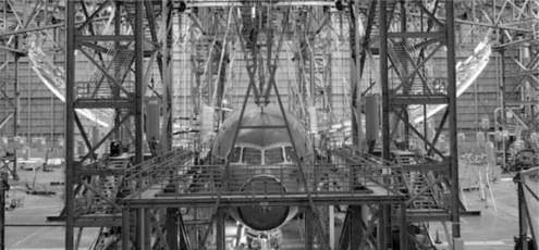
Impact damage in composite materials differs significantly from impact damage in metals. Where metals will typically provide easy evidence of a significant impact by denting, composites may not show any evidence at all. This is most true for early generation, untoughened composites where significant subsurface damage (see Fig. 8.2) may occur with little or no evidence on the surface of the laminate. Later generations of composites are tougher and will sustain much less damage from an impact equivalent to that shown in Fig. 8.2, but visual observation of the damage may still be difficult.
8.2 Ultrasonic C-scan image of an impacted untoughened carbon/epoxy composite. The top image shows the amplitude plot of the ultrasonic signal and outlines the total area of damage. The bottom image shows a time-of-flight image that indicates from which layer the ultrasonic signal first reflects. Note that the damage progresses layer by layer along the direction of the fibers in each ply in a ‘spiral staircase’ pattern with the damage area increasing with increasing depth through the laminate.
Because impact damage in composites may be so difficult to see, some criteria have been developed to incorporate this feature into the design of composite structures. For example, test methods have been developed for determining the compression strength after impact (CAI) for composites [11] and barely visible impact damage (BVID), which is typically in the range of 0.5–1.0 mm in depth (see, for example, Ref. [12]). The term visible is used since the primary inspection method in current use involves visual observation, though the development of automated techniques (see, for example, Refs [13] and [14]) is ongoing to try to minimize the human element in damage detection.
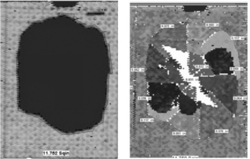
BVID is used to define the critical damage level that establishes the design strength values to be used in analyses to demonstrate compliance with the regulatory ultimate-load requirements of FAR 25.305 (Fig. 8.3). The extent of such damage is established during material and subcomponent development in the early parts of the design phase. The impact energy level required to impart BVID is then used for sizing impact critical structures. A general approach for dealing with BVID and impact damage tolerance is shown in Ref. [15].
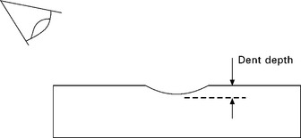
8.3 Schematic of BVID where the dent depth must be above a predetermined critical size in order to meet the definition of barely visible. In general, structures are designed to be able to withstand this up to this level of damage such that knockdowns in strength values based on this level are used for designing structures.
8.3.3 Environment
In addition to basic structural requirements as described above, there are many sources of potential damage related to the in-service environment, which includes weather (heat, humidity, cold, rain, wind, snow, ice, hail, dust, lightning), animal interactions (birds, insects, mammals, reptiles) and ground-based operations (taxiing, maintenance, servicing, etc.). Although all organic polymers are highly susceptible to degradation from ultraviolet (uv) light, this is already well known such that any polymer-matrix composite that would otherwise be exposed to uv light is either coated or painted to prevent any uv light from affecting the composite. The problems posed by environmental exposure were recognized early on in the use of composites for aerospace. Hedrick and Whiteside [16] show some results for moisture, temperature, and lightning and some means for dealing with these problems. This section will consider environmental effects and how they contribute to damage in composites.
Of primary concern is impact damage, which can either be caused during flight or during servicing and ground operations. Impacts during flight are generally one of the following: bird strikes; hail (ice) impingement; airborne particulates/debris. Ground-based impacts typically result from tool drops; ground debris on runways; direct impact from ground equipment; and windblown debris. Damage from the impact of ground equipment like service vehicles generally causes very large, highly visible damage that prevents an aircraft from operating such that it must be taken out of service to be repaired. As it is not practical to design aircraft to withstand such impacts (just as it is impractical to design cars to not sustain damage above a certain level of impact), such impacts will not be discussed here.
Bird strike
The US Department of Agriculture compiles a database of all reported bird/wildlife strikes to United States civil aircraft and to foreign carriers experiencing strikes in the United States through an interagency agreement with the FAA. Between 1990 and 2008, 89,727 animals were struck with the vast majority (97.4%) being birds [17]. Because the frequency of impacts due to animals other than birds is small, only bird strikes will be discussed here. The number of reported bird strikes has been increasing and this is believed to be a combination of increased awareness and reporting as well as increases in both bird populations and flight frequency. Most bird strikes occur during descent, approach, or climb, and not during cruise.
Some countermeasures are used to minimize the likelihood of bird strikes, but notwithstanding the fact that a low percentage of flights actually suffer from high-velocity bird strikes, it must be assumed that a structure will sustain a bird strike in designing aircraft structures to ensure vehicle and passenger safety. Indeed, the FAA requires such performance in FAR Part 25, Sub-part 25.571 [1] ‘Damage-tolerance and fatigue evaluation of structure’, where it is stated that ‘The airplane must be capable of successfully completing a flight during which likely structural damage occurs as a result of impact with a 4-pound [1.8-kg] bird when the velocity of the airplane relative to the bird along the airplane’s flight path is equal to Vc [design cruise speed] at sea level or 0.85 Vc at 8000 ft [~2440 m], whichever is more critical.’
With increasing use of composites in aircraft like the Boeing 787, the need for robust design tools has become even more necessary. Indeed, Boeing has developed [18] some simulation techniques for characterizing bird strikes in order to certify composite structures for airworthiness. In this work, finite-element models were developed to simulate a bird strike and the models were corroborated with test data to prove their validity.
Lightning strike
The FAA regulations [1] provide the guidelines for lightning protection for airframes and these requirements are identical for all vehicle categories. Specifically, the requirements appear in Section 25.581 of the regulations ‘Lightning Protection of Structure’, which requires that aircraft be able to withstand a lightning strike without suffering catastrophic damage. Additionally, guidelines for military aircraft are contained in MIL-STD-464 [19].
Thus, it is the goal of designers using composites to prevent lightning strike from causing catastrophic structural damage and to prevent hazardous electrical shocks from reaching vehicle occupants and flight-critical electrical systems. Damage to electrical systems may cause a loss of aircraft flight-control capability. Lastly, it is imperative to prevent any lightning strike from causing sparking in fuel tanks that may lead to the ignition of fuel vapors. Composite materials present a unique challenge as they are, for the most part, non-conducting. Although carbon fibers may have some electrical conductivity along their length, they have far lower conductivity transverse to the principal fiber direction. Additionally, polymer matrix resins used for aerospace are electrical insulators. For these reasons, add-on solutions are used to prevent significant damage from affecting the underlying composite structure.
For non-metallic components such as composites, meeting the requirements may be accomplished by appropriate design considerations. This is especially important as polymeric composites have electrical conductivities roughly three orders of magnitude lower than aluminum, which is the standard material for nearly all metallic aircraft. Thus, it is necessary to incorporate lightning strike protection into composite design.
In order to provide protection from lightning strikes to composites, metallic materials like those shown in Fig. 8.4 are typically utilized to divert the electrical current from a lightning strike so as not to endanger the airplane. Different parts of the structure may have different lightning strike requirements as shown in the schematic in Figure 8.5, which shows zones susceptible to different likelihoods and severities of lightning strike. Methods for meeting the requirements for lightning strike protection are not rigidly specified to allow manufacturers to adopt different certification strategies. Zone 1 regions are likely to experience initial lightning strikes and first-return strokes. Zone 2 regions are likely to experience subsequent swept strokes, or re-strikes. Except for a few protruding areas of the airframe, such as the wing tips and nose, which comprise Zone 1, the vast majority of the airframe belongs to Zone 2. In addition to the zoning information provided by SAE International as shown in Fig. 8.5 [20], SAE also provides aerospace recommended practices (ARPs, available at http://www.sae.org) that can be utilized to aid designers in meeting these requirements.
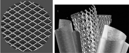
8.4 Examples of Astrostrike™, (http://astrosealproducts.com/pages/what%20is.html), left, and Dexmet™ (http://www.dexmet.com/Dexmet-Products.html), right, expanded-metal meshes used for lightning strike protection in composite and other structures.
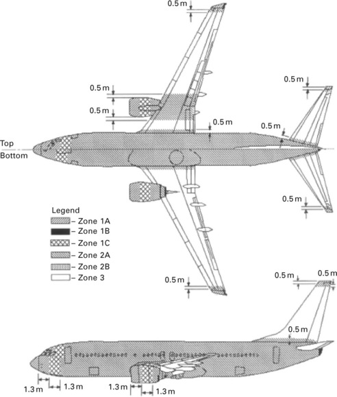
8.5 Lightning strike zones as defined in SAE ARP5414 [20]. Reprinted with permission from SAE ARP5414 © SAE International.
The metallic materials mentioned above for providing lightning strike protection on composite structures are used near the outer surface of the composite for several reasons. First, it is essential to keep the high energy of a lightning strike away from any combustible materials, especially fuel that may ignite if exposed to a sufficiently large spark. Second, keeping the energy on the surface serves to mitigate the amount of damage that might be otherwise caused by a lightning strike. Figure 8.6 shows a comparison of test panels subjected to a simulated Zone 1A strike with and without lightning strike protection. Severe localized delamination and heat damage is observed without lightning strike protection. In addition to providing the high surface electrical conductivity necessary for diverting the energy of a lightning strike, designers must also complete the electrical circuit by establishing a current return or grounding plane for the electrical energy. Metallic aircraft, by contrast, can utilize the entire airframe as a grounding plane.
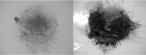
8.6 Effects of lightning strike protection (http://www.dexmet.com/Lightning-Strike-Protection/Lightning-Strike-choose.html) on a composite panel subjected to a simulated Zone 1A strike where incorporation of a metallic mesh (left) dramatically reduces the damage caused compared with that seen in an unprotected panel (right). Note delamination and heat damage in panel on right and restriction of effects largely to the surface on left.
The necessity of efficient, lightweight lightning-strike protection for aircraft has become much more important recently with the introduction of the Boeing 787 Dreamliner and the Airbus A350XWB, which are the first two large commercial transports to use composite materials for the majority of their primary structure. Because of these new, significant applications of composites in aircraft structures and the high likelihood that this trend will continue with other new commercial transports, there is active work in developing newer and improved approaches to handling the problem. Some of this work is related to modeling lightning strike (e.g. [21] and [22]) to be able to design full systems that incorporate lightning-strike protection instead of the current state of using an add-on solution like metal meshes. One example of a systems-level approach is the creation of a Faraday cage within the structure as outlined by Hawley [23].
Moisture: rain and ice
Composite materials all pick up some amount of moisture depending on the chemical composition of the matrix resin used. Additionally, stress can enhance moisture absorption in composites [24] so that the effects in service may be more severe than simple tests may suggest. Once inside a polymer, moisture causes the modulus to decrease, especially at elevated temperatures. Furthermore, moisture depresses the glass transition temperature (Tg) of polymers, thereby limiting the upper use temperature. In all specifications for aerospace composites, testing is performed on composites that contain moisture to measure the property reductions at elevated temperatures. In these tests, moisture is introduced into the composites by either immersion in water at an elevated temperature for a period generally not less than 14 days or by exposure of the composite specimens to high humidity for a similar period of time. A general rule of thumb is a 25–30 °C reduction in the upper use temperature of a composite after significant exposure to moisture.
In addition to moisture absorption within laminates, composite structures, in particular sandwich structures and especially honeycomb-core sandwich structures, are subject to moisture ingress into the core material [25]. Although moisture that accumulates within a foam or honeycomb is a concern as it adds weight to an aircraft, the potential for the moisture to suddenly vaporize, which causes a large pressure increase inside the sandwich structure that may cause the skins to delaminate from the core, is the main source of concern. Such a failure was purported to be the cause of the failure of the X-33 cryogenic tank [26] which was a honeycomb-core sandwich structure.
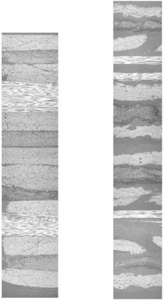
It is well known that moisture acts as a plasticizer on polymer matrices and there is evidence of microcrack formation due to cyclic moisture exposure [27, 28] and to combined moisture and thermal cycling [29]. An example of microcracking caused by combined moisture and thermal cycling is shown in Fig. 8.7. It is also sometimes believed that microcracks such as those caused by moisture and thermal cycling can be repositories for moisture accumulation that could create further problems due to ice formation. However, this can only occur if the size of the microcracks is sufficient to allow the formation of ice crystals [30] and, if this is not the case, then the liquid present in these cracks becomes a vitreous solid [31] instead of ice. Because the water does not form ice if the cracks are sufficiently small, it does not experience the large volume expansion caused by the phase change from liquid water to ice. Because the density of liquid water and vitreous water remains essentially the same from 0 °C to −175 °C [32], no such volume expansion occurs.
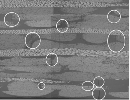
8.7 Cross-section of a laminate showing evidence of microcracking due to combined thermal–moisture cycling. White circles indicate the presence of transverse microcracks.
Ice is a factor when it accumulates on aerodynamic surfaces but as this does not cause direct damage to the underlying composite structure, it will not be considered in this chapter. Ice is also a concern when it impacts the structure in the form of hail. It is a variant of impact damage as previously discussed above, but some details particular to hail will be discussed below.
Moisture inside cracks is of concern in a similar manner to that noted for honeycomb-sandwich structures above when the temperature rises sufficiently and rapidly under a phenomenon called ‘thermal spike’, which may cause this trapped water to suddenly turn to steam and cause damage within a composite structure [33, 34]. It has been observed that thermal spikes cause internal damage and these are a particular concern in both supersonic vehicles and exhaust-washed structures. McKague et al. [33] performed simulated flight cycles involving a subsonic mission, 54 °C for 90 minutes, and for a flight involving a subsonic segment with a supersonic dash, which caused rapid heating to a peak of 149 °C followed by rapid cooling. The simulated thermal spikes caused permanent changes in the subsequent moisture–diffusion behavior of the carbon-epoxy such that both the amount and rate of moisture absorption were significantly increased. In contrast, the subsonic exposures caused no detectable change in diffusion behavior. Similar results were observed by Adamson [35] who also observed irreversible damage in composites due to thermal spiking.
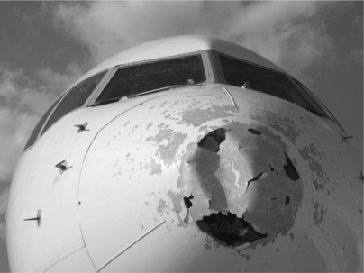
Moisture is also a problem when it freezes and becomes hail. Hail impact at the high velocities of flight can cause significant damage to aircraft, as evidenced by the large amount of damage seen in Fig. 8.8, which shows a metal aircraft. Composite structures will, naturally, have different failure modes than metallic ones with laminates experiencing similar damage patterns as those from other impacts like tool drop or bird strike. In addition to the size of the impact from hail, it is the potentially large number of impacts within a short time period that is of most concern and, because these types of events are significantly enough likely, structures must be designed to be able to carry design loads after such impacts.
For honeycomb-sandwich structures, hail impact damage was modeled by Horrigan and Aitken [36] based on observed damage modes that strongly resemble the quasi-static indentation damage shown in Fig. 8.9 [37] where damage is due to localized, near-surface cracking in non-metallic honeycomb and near-surface buckling in metallic core. Higher impact levels will cause skin failure and direct impact on to the underlying honeycomb structure [38].
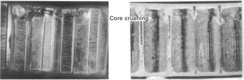
8.9 Examples of near-surface damage in honeycomb-sandwich structures from localized indentations [37]. Note core buckling in aluminum core on left and core crush/resin cracking in non-metallic phenolic/Nomex core on right.
Simulated testing of hail strikes has been performed [39, 40] to better understand the phenomena associated with these impacts. The experiments of Kim et al. [39] show a linear relationship between the peak measured force and the projectile kinetic energy, regardless of projectile size, and it was observed that, in composite panels, there is a linear relationship between the kinetic energy at which failure initiates and the thickness of the panel. At the failure initiation threshold, multiple localized failure modes may be observed and non-orthogonal impact energy levels may be accurately estimated using simple trigonometric scaling. Mahinfalah and Skordahl [40] showed how most of the impact energy from hail impact goes into disintegrating the hail such that little internal damage was observed, especially in comparison to similar mass aluminum projectiles, which were much more likely to cause internal damage to composite structures, though, below a certain threshold size and mass, no internal damage was seen. Subsequent fatigue testing was consistent with these observations as no significant changes in behavior were observed. More recent work [41, 42] has focused on trying to model hail impacts to enable predictive models to be used to improve composite designs.
8.3.4 Non-environmental considerations
In addition to environmental exposure, there are numerous other considerations from man-made causes. Because these exposures are generally well known, they are all accounted for during material development and structural design. The sections below outline some of these areas of concern.
Fluids
Aerospace composites must be able to withstand a large number of different fluids. Not least of these is moisture, which, in addition to the problems outlined above in honeycomb-sandwich structures, diffuses into polymer matrices. A general overview of the effects in composites is given by Weitsman [43] who notes that, although there are good means for characterizing fluid sorption, how these relate to durability and strength is much more problematic and requires that a sufficiently robust database be generated to properly account for degradation and damage due to fluids.
In addition to ever-present moisture, composites are also exposed to hydraulic fluids (e.g. Skydrol), fuel (e.g. JP-4), cleaning solvents (e.g. methyl ethyl ketone, methylene chloride, etc.), and a wide variety of other fluids used in servicing and maintaining aircraft. As fluid exposure/conditioning can induce strong matrix plasticization, it is possible that significant reductions in static and fatigue performance may result from the presence of fluids as compared to unconditioned laminates. Sala [44] summarizes the effects of various fluids on composites, noting that impact performance may also be degraded substantially due to fluid exposure.
For composites made with fiberglass, aramid (e.g. Kevlar®, Twaron®), or other organic fibers (e.g. Vectran®, Zylon®, Dyneema®, etc.), the susceptibility of the fibers to fluid degradation must also be taken into account. In cases where the fibers are not sufficiently compatible with likely fluids to which they would be exposed, then they may not be used for those structures. In these cases the use of carbon fibers is especially useful as it is generally chemically inert under normal usage in aerospace applications in addition to its high specific strength, which is the main reason for its ubiquitous use in aerospace composites.
Because carbon fibers are predominantly used for aerospace applications, it is the matrix susceptibility to degradation that is of most importance. In all specifications for aerospace composites, there are specific requirements for fluid resistance. Thus, there are built-in safeguards to prevent the use of unsuitable materials that will be exposed to harsh fluids.
Temperature
As mentioned previously, polymers are affected by temperature. In general, this concerns the change in mechanical properties that results from the softening of a matrix resin at elevated temperatures, as shown in Fig. 8.10. Cyclic temperature exposure is also important and is analogous to cyclic fatigue where, instead of direct mechanical loading, stresses are induced from the differences in the coefficients of thermal expansion between the fiber and matrix. Indeed, Li et al. [29] note that most microcracking in cyclic thermal fatigue occurs at low temperatures and also that increases in the ratio of high temperature to low temperature increase the density of cracking that is observed. The increased susceptibility to microcracking at low temperatures is also noted by Tsotsis [30] who cites prior research [45]–[47] on the characterization of polymeric composites at cryogenic temperatures.
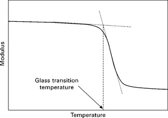
8.10 Schematic of glass transition temperature (Tg) as determined from drop-off of the real (in-phase) part of modulus response in a dynamic mechanical analyzer. This method is used in aerospace composites as it relates to mechanical properties used for designing parts and structures. The tan δ determination of Tg from the ratio of the imaginary (out-of-phase) and real parts of the modulus is useful for thermodynamic and rubber-elasticity considerations, but not for structural composites.
Another issue of concern is long-term exposure to elevated temperatures. There is a large body of work on long-term thermo-oxidative degradation of polymer composites and this is summarized by Tsotsis [48] who notes that, in the absence of highly accurate, reliable modeling techniques to characterize long-term aging of polymeric composites, it is necessary to use materials that will remain essentially unchanged in their performance and properties during their desired lifetime. In fact, this is already the de facto approach used with polymeric composites, though no formal guidelines exist stating this.
All aerospace composites are used well below their glass transition temperature (and especially their wet glass-transition temperature) such that thermo-oxidative effects are largely not present. The only exceptions are for composites used for space applications where the exposure times are sufficiently short that it is highly unlikely that any degradation of any significance will occur during the lifetime of the structure (generally only a few hundred hours of exposure at maximum use temperature). For composites based on higher-temperature matrix resins like bismaleimides and polyimides, the desired lifetime at temperature will determine the allowable upper use temperature in service.
High-speed airflow
For supersonic aircraft temperature also can become a key design limiting parameter. A National Materials Advisory Board publication [49] summarizes the requirements for supersonic aircraft quite well based on prior studies, many related to the Concorde, which are also cited in this reference. At Mach 2.0, the skin temperature remains well below 100 °C but rises to 120 °C at Mach 2.2 and further to 150 °C at Mach 2.4. Usually, at Mach 2.0 or below, thermo-oxidative degradation is not a concern. However, as the skin temperature rises to 120 °C or above, thermo-oxidative degradation and its potential consequences can either prevent composites from being used at all or require them to be protected – usually through insulative layers – such that they operate at more benign temperatures. In many cases, the use of insulation is not permissible (such as on aerodynamic surfaces or parts exposed to high-speed airflow), but, recently [50, 51], some development on thin thermal-barrier coatings has been done to try to address this problem. The goal of thermal barrier coatings is to reduce the temperature of the substrate such that it operates at a more benign temperature where it is stable. As mentioned above, composite materials considered for use at elevated temperatures must be chemically stable during their desired lifetime or other solutions must be found.
In subsonic flow, turbulence, gusts, and flutter, rather than temperature, can affect the design of aircraft structures (note that these loads also persist in supersonic flow). These dynamic loads are a result of instabilities in the atmosphere as they encounter aerodynamic surfaces, such as a wing. Because these loads are generally much larger than general flight loads, they must be considered in the proper sizing and design of aerodynamic surfaces. Furthermore, they must also be taken into account when simulating flightload spectra both experimentally and analytically.
In order to certify aircraft structures, it is essential to eliminate flutter entirely from the flight spectrum. In order to do this, the analytical techniques differ somewhat from those for isotropic, metallic aircraft because composite materials involve non-classical effects such as transverse shear, warping inhibition/restraint, non-uniformity of contour-wise shear stiffness, and other 3D effects not present in metals. Shokrieh and Behrooz [52] demonstrate some finite-element techniques that may be used to eliminate flutter from a composite-based design and Kim and Hwang [53] showed techniques for dealing with gust loads for composite wings. Qin et al. [54] modeled composite wings using anisotropic thin-walled beams to represent the composite structure and showed how lay-up tailoring could be used to meet the loading requirements from gusts and how elastic coupling could be used to eliminate flutter. Some more general discussions of analytical methods to characterize flutter are given in Refs [55]–[57].
Fire safety
As for structural loads, there are strict requirements for fire safety on aircraft. These are outlined in the FAA guidelines for flammability [1] under FAR 25.856, which gives smoke-density and heat-release requirements, among other properties, and materials must be tested according to the FAA Aircraft Materials Fire Test Handbook [58], meeting these safety regulations in order to be certified for use on commercial aircraft structures. Most safety regulations pertain to the interiors of aircraft, where fires are most likely to start. However, because these materials are not primary load-bearing materials for the aircraft structure, they will not be considered any further here.
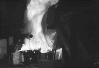
The growing use of composites over the past several decades has led the FAA [59] and other aviation-based international governing bodies to design requirements and certification procedures for composite-based aircraft structures. Fires involving composite structures can be quite difficult to extinguish, as shown in Fig. 8.11, and the main requirement, as for aircraft interiors, is to allow sufficient time for passengers to exit safely from a burning aircraft before heat and smoke adversely affect them. In this case, external fires, usually beginning as an engine fire, such as shown in Fig. 8.12 [60], are the primary concern in structural fire safety. Such fires have been characterized by the FAA [61] to help develop certification requirements and accompanying test methods for certification. In order to simulate fuselage burnthrough, the FAA specifies a modified oil burner to simulate the effects of an external fuel fire on an aircraft fuselage and interior components (Fig. 8.13) [62]. The burner used in this test is a typical home heating-oil burner, but using Jet A jet fuel in the burner.

8.11 Aftermath of the crash and fire of a composite-based Air Force B-2 bomber in Guam in December 2008. It took over six hours and 300,000 liters of water and nearly 10,000 liters of aqueous film-forming foam (AFFF) to extinguish [59].
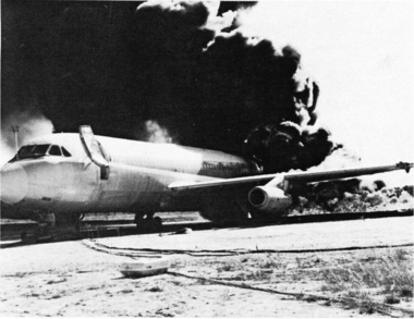
8.12 Flame impingement from a simulated engine fire [60].
8.13 Oil-burner test used by FAA to evaluate materials for fuselage burnthrough capability [61].
The requirements for the fire safety of structural composites are no different than those for aluminum aircraft, and standards for compliance are listed under the FAA Flame Propagation test, FAR 25.856. The ability of a fuselage to resist penetration from an external fuel fire is directly related to the thickness and material of the skin. However, differing local structural load and other design requirements will necessarily create considerable variations in local skin thickness meaning that different airplane types will have different burnthrough resistances. Other factors internal to the airplane can also affect penetration of an external fire into the fuselage interior. For example, differences in aircraft ducting that affect air return within the cabin can influence the time required for an external fire to penetrate through the fuselage.
According to FAR 25.856, a fuselage must be able to resist flame penetration for at least four minutes. It is not essential that the fuselage structure itself be able to withstand this, but that the aircraft (the combination of the fuselage, thermal/acoustic insulation, fire barrier materials, and sidewalls plus any active fire prevention equipment/systems) be able to meet the requirement. For example, Mueller et al. [63] describe a conceptual design wherein the cargo floor comprises a fire barrier to minimize the amount of the addition of non-structural burnthrough protective materials. Other concepts based on the use of intumescents, such as by Heitkamp [64], or using inorganic materials to act as fiber barriers [65] are also known.
Because the fuselage must be dealt with as a system, the type of composite material used to fabricate a fuselage may not be the prime determining factor in the fire-safety performance of the fuselage. However, composite materials that have better flammability properties than others should, in principle, reduce the need for other non-structural materials to meet the mandated fire-safety requirements.
Ground-based damage due to human error
Ground-based damage is principally caused by maintenance crews impacting airframe structure, tool drop during maintenance, or from errors in ground-traffic control. The first of these is generally related to impacting the airframe with ground vehicles such as forklifts, refueling trucks, food-servicing trucks, etc. For the most part, these types of impacts are at levels much greater than can be practically designed for. In these cases, it is more important to consider how to repair such structures than how to prevent this type of damage.
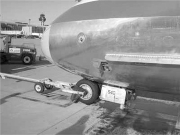
The National Business Aviation Association (NBAA) has developed some best practices for preventing ground damage [66]. In this study, it was noted that nearly half of ground-based damage in business jets occurs during the towing of aircraft and approximately a quarter attributable to both ramp movements and ground-service equipment. Although these guidelines were writing specifically for business jets, similar types of damage can be inflicted on large commercial aircraft – as seen in Fig. 8.14, which shows landing gear that was damaged by towing an aircraft with its brakes locked – and on military aircraft [67] where struts and landing gear are among some of the damage caused during ground-based maintenance.
Wenner and Drury [68] evaluated some of the reasons for the human errors that cause ground damage to large commercial aircraft. The trends in types of damage differ slightly from the NBAA results mentioned above with over 60% of the damage occurring when the aircraft is parked. It is interesting to note that nearly 72% of all damage results from equipment, vehicles, or hangar doors impacting the vehicle. As mentioned previously, it is not weight-efficient to design aircraft to withstand such large impact levels, so such damage will necessitate repair to the damaged structure. In contrast, tool drops represent only 3% of all ground-based damage. Tool drops have impact energies similar to hail or debris (e.g. rocks and stones) and, combined, these impacts occur in sufficiently high probability that they must be included in materials specifications and structural designs. The impact energy imparted by a tool drop is used to specify the levels in tests like compression after impact (CAI) [11]. Means for dealing with impact damage will be discussed below.
8.4 Designing for damage in composites
There are two basic approaches to improving the damage tolerance in composite materials-based designs:
In reality, these two approaches are closely linked and rely on each other to some extent. For example, joints made using co-bonded, secondarily bonded, bolted, pinned, stitched, or other means are combinations of a materials approach and a structural design one. Furthermore, each joint type will behave differently under load, which will influence both materials and structures in adjacent structures on the aircraft. Some materials and design approaches to improve damage tolerance will be described in detail below.
8.5 Materials-based approaches
The information presented above shows that a key to implementing composite materials on a wide scale is the ability to improve their impact-damage resistance. Most work in toughening composites has focused on the improvement of neat-resin fracture toughness and its relationship to composite fracture toughness, composite impact damage, and delamination resistance. In the bulk matrix, the fracture toughness is solely a function of the matrix itself and the confinement effects of the surrounding fibers. This may be modified if particulate tougheners, such as rubber particles, are added to increase the matrix fracture toughness. In composites, the relationship between improved matrix toughness and improved composite toughness is less clear. In this case, it is a function of the neat-resin fracture toughness, the composite Mode II fracture toughness, and the fiber architecture, as well as other less important factors.
Scott and Phillips [69] noted that in carbon-fiber-reinforced plastics (CFRPs), the initial resistance to crack propagation parallel to fibers is determined largely by the matrix toughness. Moreover, the addition of butadiene-acrylonitrile co-polymers (e.g. CTBN) were found to increase neat-resin fracture toughness by an order of magnitude, but the large increases obtained in the neat resin were not obtained in CFRPs; instead only modest increases were achieved. The authors concluded that the thickness of resin film through which the crack propagates suppressed the toughness increases observed in the neat resin. Other authors, such as Bascom et al. [70], have also observed poor transfers from neat resin Mode I fracture toughness improvements into the composite. Furthermore, Russell and Street [71] observed that static composite toughness did not correlate with interlaminar fatigue resistance. Clearly, solutions to composite toughening must be based on composite approaches and not on neat-resin-based ones.
8.5.1 Toughening in prepregs
Previous methods of providing toughness to composites have focused on two approaches and applied these only to prepreg materials. The first approach (Method 1) is to blend thermoplastics into a matrix resin. Such thermoplastics may be dispersed or dissolved into the base matrix resin (e.g. US 4,656,207, 4,680,076 from Hercules Corp., US 5,045,609, 5,248,711 from Hexcel Corp., US 5,266,610 from ICI Composites Inc., US 5,434,226 and EP0384896 from Ciba-Geigy, among others). Upon cure, the thermoplastics either are indistinguishable from the resin, phase-separate from the resin, or are distributed as discrete particles in the matrix. These thermoplastics may be elastomeric, such as rubbers, or simply comprise tough materials like polyethersulfone. The second approach (Method 2) is to provide a discrete interlayer between the plies to help deflect damage growth. American Cyanamid (US 4,539,253, 4,604,319, 4,957,801) and Ube Industries (US 4,868,050) developed a solid-thermoplastic-interlayer prepreg system (Method 2A) whereby a thermoplastic film was directly laminated onto the prepreg. Toray, using a similar philosophy, developed an interlayer approach (Method 2B) based on coated particles (US 5,028,478 and US 5,413,847) that are applied to prepreg by sprinkling them on to the resin film prior to consolidation with the fiber. The weight of interlayer materials in the Toray approach ranges between 2 and 4% of overall weight. American Cyanamid (US 5,057,353) patented a similar particle-based toughening approach using polyimide and polysulfone particles.
The two toughening methods work on different principles. The dissolved/distributed thermoplastic approach works by improving the resistance to fracture of the base resin system. The interlayer approach does nothing to improve the fracture toughness of the matrix resin, but acts as a mechanical toughener by deflecting crack direction to require more energy to be expended per unit area of crack growth and thereby improves the fracture toughness of the composite, which is, indeed, the ultimate goal.
One drawback to the dissolved/distributed thermoplastic approach (Method 1) is that the thermoplastics that are typically used have lower mechanical properties (especially modulus) than the matrix resin into which they are introduced. This has the effect of reducing matrix-based composite properties such as compression and shear. The interlayer approach (Method 2) does not directly affect the matrix–resin properties, so that, in general, it is less likely to reduce matrix-based composite properties.
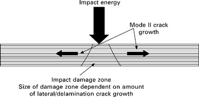
In examining the effects of toughening on impact, it is helpful to examine the impact event itself. A schematic of an impact is shown in Fig. 8.15 whereby impact energy is imparted to the surface of a laminate, producing a pressure wave whose energy must be accounted for by panel deflection, heat, noise, and, most importantly, damage. In the Method 1 approach, cracks in the resin require more energy to form. These are typically Mode I cracks that are perpendicular to the laminate surface. Transverse crack growth in between plies in the plane of the fibers is generally not suppressed by matrix toughness improvements. The Method 1 approach simply requires that more energy be required to open cracks caused by impact.
In the Method 2A approach of American Cyanamid, damage growth is suppressed by preventing Mode I cracks from propagating easily from one ply to the next and by deflecting such cracks along the thermoplastic film. In the Method 2B approach of Toray, the particles act as local crack deflectors in the interlayer between plies. As a crack tries to grow laterally, it must go up, over, and around each particle, thereby increasing the amount of crack surface area required for a unit length of lateral crack growth. Both of these Method 2 approaches affect crack direction as their principal method of improving impact-damage resistance, as is shown schematically in Fig. 8.16.
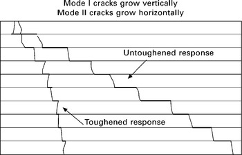
8.16 Schematic of cross-section of impact damage in a composite laminate for interlayer-toughened and untoughened materials from an impact centered at the upper left corner. Mode I cracks grow vertically, mode II cracks grow horizontally.
American Cyanamid disclosed the use of a fabric interlayer in US 4,539,253. In this patent, compression after impact (CAI) values between 207 and 303 MPa were reported after 6.7 J/mm impacts with the interleaf present. The base resin without any interleaf had a CAI near 207 MPa. One explanation for this small change between the interleaved material and the non-interleaved material is provided by Groleau et al. [72], who noted that as long as interlayer materials (in their case polyamide particles) did not significantly alter the ability of the interply material to deform plastically, the interlayer material and geometry should not play a large role. In matrix systems with little or no ductility, the authors stated that the interlaying material must be tailored to first initiate microcracking in the matrix and should also be able to have large plastic deformation.
Aksoy and Carlsson [73] investigated thermoset and thermoplastic interleaves and found both types of interleaves enhanced the interlaminar fracture toughness to a great extent. Thermoplastic interleaves were found to be more effective than the thermoset interleaves because of the larger energy-absorbing capability of the thermoplastic polymers they investigated. They further found that the fracture toughness increased steeply with interlayer thickness at small interleaf thicknesses and leveled off to a relatively constant value at larger interlayer thicknesses. Thermoset interleaves exhibited cohesive failures, microcracking, and plastic deformation and thermoplastic interleaves displayed adhesive failures, a limited degree of microcracking, and material yielding.
Lee et al. [74] examined the use of nonwoven carbon tissues (NWCTs) by placing these in the center of prepreg-based lay-ups. The Mode II fracture toughness increased by between 26 and 205% due to the NWCT, depending on the crack geometry. The improvement was attributed to short-fiber bridging provided by the NWCT.
8.5.2 Liquid-molding and prepreg-based toughening
Both of the prepreg-based toughening methods are generally incompatible with liquid molding. The introduction of thermoplastics into a matrix resin dramatically increases its viscosity if dissolved into the resin. If the thermoplastic particles are dispersed, the particles will be filtered out by any preform into which they are introduced. There are some examples of resins that contain dissolved thermoplastics that have been processed via resin transfer molding (RTM) and resin film infusion (RFI), but these contain thermoplastic components that must be heated to fully melt them prior to infusion. For low-pressure, low-temperature infusion processes like vacuum-assisted resin transfer molding (VARTM), the high viscosities of the thermoplastic-modified resins are unacceptable.
The use of a film-based interlayer like American Cyanamid’s approach is completely incompatible with any liquid-molding process because the film acts to block resin flow and will prevent wetting out of any preform using such technology. The use of particulates such as in Toray’s method has the same filtering problem as the undissolved thermoplastics described above. For these reasons, a preform-based toughening approach is required.
8.5.3 Preform-based toughening
Preform-based toughening is complementary to the interlayer- and matrix-focused approaches described above. Here, preforms will mainly refer to utilizing textiles to create dry fiber forms for making unitized or tailored structures that cannot be realized using traditional manufacturing approaches. Preforms will also include prepregs, where applicable, though most textiles-based approaches are incompatible with prepregs.
Stitching
Toughening approaches with preforms have been developed previously. Most notable was the use of transverse or z-direction stitching during Boeing’s Advanced Subsonic Technology Composite Wing Program (NAS1-20546) [75], which showed significant improvements in impact damage tolerance as a result of stitching. Other studies such as those by Larsson [76], Jain et al. [77], and Sharma and Sankar [78] also report significant increases in damage tolerance and fracture toughness due to stitching. Although stitching provides significant out-of-plane property improvements and drastically reduces the amount of fasteners required if used to fabricate integrated preforms, it does so at a cost. This cost includes the amount of time required to provide for field stitching (i.e. stitching not used solely for assembly or attachment) as well as a reduction in in-plane properties due to the multiple penetrations of the stitching needle through the preform, as noted in [75] and by Mouritz et al. [79] and Reeder [80].
The result is that it is desirable to use stitching only where it provides the most benefit and limit the amount of field stitching required. This last point is the key driver for searching for other preform-based toughening methods that would provide the same benefits in toughness as stitching, but at a lower cost.
Tackifiers
One such candidate method is the use of toughening tackifiers. These have been used for some time and are formulated in two different ways. One is to use a partially solvated version of the matrix resin (the solvent provides greater tack and flow than the unsolvated resin) and another is the use of tacky, rubbery compounds. In both cases, the tackifiers are either sprayed or brushed on. In certain instances, heat may be used to apply the tackifiers, but this is more the exception than the rule. Hillermeier and coworkers [81, 82] describe some approaches and benefits of tackifier tougheners.
Tackifiers have several potential problems. First, there is a limited outlife or handling time on the preform. Solvent-modified tackifiers will lose their solvent to the atmosphere if exposed for too long a time, thereby negating their tack. In the case of systems that comprise a version of the matrix resin, the catalyzed resin may advance if exposed for too long a time, also eliminating the tack. Second, tackifiers may inhibit resin flow during infusion [83]. Third, in low-pressure processing, tackifiers will prevent full consolidation of a preform resulting in too high resin contents and corresponding low fiber volumes as shown in Fig. 8.17. Fourth, the presence of uncatalyzed, chemically incompatible, and/or unevenly distributed tackifier reduces the mechanical properties of molded composites [84].
Interlayers
Examples of attempts to use interlayers in fabrics are available in the patent literature. For example, Mitsubishi (EP 1 175 998) made laminated products formed of reinforcing fibers in which thermoplastic resin layers were provided between layers of the reinforcement fiber. The thermoplastic resin layer was described in the form of a porous film, fiber, network structure, knitted loop, etc. The laminated product used a thermoplastic layer of sufficient permeability between the layers of reinforcing fibers so as not to inhibit liquid resin flow during a liquid-molding process. However, the processes described in EP 1 175 998 produce preforms that have poor handling characteristics and, thus, are not very stable during resin infusion. In another example, under EP 1 125 728, Toray uses short fiber, non-woven fabrics that have a portion of the fibers of the non-woven fabric pass through the main reinforcing fiber to integrate the non-woven fiber to the fiber reinforcing material. Claims are also given for the use of pressure-sensitive adhesives instead of fiber entanglement for attaching the non-woven to the fiber-reinforcing material. Lastly, it also claimed by Toray to use a non-woven material that comprises both low-(5–50%) and high-melt materials such that the fabric is attached to the fiber reinforcing material by melt-bonding the low-melt material.
Recently, Hogg [85] discussed the use of thermoplastic fibers to improve the toughness of composites made with brittle resins, such as untoughened epoxies. In this work thermoplastic fibers were introduced either by commingling or by placing veils between layers of structural fibers. Both methods showed improved impact resistance compared with unmodified laminates using otherwise identical materials and lay-ups.
A successful implementation of non-woven interlayers on the Boeing 787 is based on work by Tsotsis [86]. In this work it was demonstrated that the use of lightweight, non-woven veils using out-of-the-autoclave resin infusion and dry-fiber preforms can be used to match the performance of the state-of-the-art prepreg composite materials. It was also noted that it is particularly important to select an interlayer material that is compatible with the matrix resin or, rather than improving impact resistance, it may actually reduce it. The incorporation of non-woven veils is compatible with existing fabric manufacturing technologies and test data showed that other properties like open-hole compression were not compromised by the veil, when selected and applied properly. Indeed, results suggest that, if the veil is melt-bonded to the carbon fiber prior to resin infusion, the veil acted to stabilize the structural fibers and to improve compressive properties.
8.6 Structures-based approaches
In addition to developing materials with improved damage tolerance, it is also possible to utilize improved design concepts that either minimize damage or minimize the effects of damage. NASA sponsored one large study [87] to examine the use in composites for fuselage structures. In this study, in addition to standard strength and stiffness design considerations, notch sensitivity, bearing and bearing/bypass properties of bolted structures, impact-damage resistance of stiffened skin and sandwich structures, as well as the strength of co-bonded and co-cured joints were evaluated in order to assess the performance of a composite design. Considerations of fluid penetrations into sandwich panels and fire worthiness were also included.
8.6.1 Bolted structures
Although not discussed previously, it is important to consider notches or holes in composites. It is desirable to have as few of these as possible, but there are manufacturing and assembly considerations that will necessitate the use of bolted or fastened (riveted) structures that require the drilling of holes for insertion of fasteners. The introduction of the hole adds a local stress concentration to the structure, which necessitates additional structure to accommodate the additional load. Furthermore, once the hole has been filled, the fastener will bear upon the hole edges. The combination of the stress concentration and the bolt-bearing must thus be used in properly designing fastened structures. When multiple holes are used (as is typical), then the interaction of the stress concentrations needs to be accounted for and, if one or more of the multiple fasteners used in these holes fails, the remaining fastened structure must be able to withstand this load redistribution.
Because holes introduce all of these design considerations, it is good practice to try to reduce the number and size of the holes introduced into any structure. However, it may be necessary to design structures to accommodate such holes even if they are not used in the initial design to allow aircraft users to perform certifiable repairs to damaged structures, especially if only bolted repairs are approved. It is this dilemma that must be taken into account when using alternate attachment methodologies like co-bonding, co-curing, stitching, and Z-pinning.
The use of large numbers of fasteners in composite structure is often referred to as ‘black aluminum’ referring to the metallic-like design concepts and the color of carbon fiber reinforced composites. Because the design of parts and structures made from composites involves more unknowns and interdependencies than it does for metals, use of such ‘black aluminum’ designs fail to take advantage of the key benefits of composites. Key differences that allow for designs not possible with isotropic materials are based on their directionality from material anisotropy, which may be tailored in a very large number of ways. Additionally, because different manufacturing techniques are used for composites compared with metals, the number and types of structural concepts that may be produced is far larger than for metals, which mainly rely on stamping, rolling, forging, milling, and welding. When textile technologies, as discussed earlier, are also introduced, the design window is further expanded. The following sections will review these options.
8.6.2 Alternate lay-up considerations
Most typically, quasi-isotropic lay-ups are used in designing laminate structures. Because there are a large number of parameters that affect structural design, as shown, for example, in Fig. 8.18 from Dost et al. [88], there are many ways to alter composite designs to achieve the same end. Moreover, as mentioned previously, Fig. 8.18 shows that composite designs are strongly interrelated with materials selections. This link is also shown in the results of Dost et al. [89] who show the relationship between laminate stacking sequence and both impact-damage resistance and residual strength. Because failure modes due to impact change both with the selection of materials (see interlayer-toughening discussion above) and how the materials are assembled (lay-up, structural concepts, etc.), it is to be expected that non-traditional lay-up schemes can be used to improve performance and to enable new types of designs using composites.
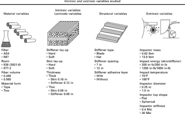
8.18 Variables influencing fuselage design as considered in NASA ATCAS program [88].
As one example of such an approach, Baluch et al. [90] examined fuselage design variables including the stacking sequence, sizes and positions of the stiffeners in a panel, section length along the longitudinal axis of the fuselage, and the skin thicknesses of the panels. Two different design approaches – foam-filled sandwich and stiffened shells – were analyzed under dynamic gust loads to determine the optimum structural combination in terms of minimum weight, stability, and ease of manufacturing. More recently, Lopes et al. [91] examined stacking sequences that move away from the standard ply orientations of 0 °, ±45 °, and 90 °. It was shown that it is possible to achieve this by dispersing the stacking sequences commonly used on composite applications in such a way that no adjacent plies had the same fiber orientation while maintaining similar axial and bending stiffness properties.
Hitchen and Kemp [92] did some early work showing that total delamination area due to impact (compression after impact or CAI) was influenced by the stacking sequence and was related to the energy absorbed during impact. It was noted that the energy required to initiate delamination was increased by placing 45 ° plies at the surface of the laminate and also by increasing the number of dissimilar interfaces. The increase in the number of interfaces means that there is a greater number of interfaces across which the energy from an impact may be dissipated. This reduces the energy available for delamination extension and, correspondingly, reduces total delamination area. This result may also be interpreted as the use of thinner plies to achieve the same thickness structure, which will be inherently more damage tolerant given the increased number of interfaces between plies. Clearly, there are limits – both from a manufacturing and material-fabrication perspective – as to how thin a ply may be within any given design.
Park [93] and Aktas and Dirikolu [94], among others, discuss the effects of stacking sequence on bolted joints. In both cases the stacking sequence was found to have a strong effect both on delamination bearing strength and ultimate bearing strength of mechanically fastened joints (pinned and bolted) in composite laminates. It was found that both the number and location of ±45 ° plies affected bearing strength. Clamping was also found to help prevent delamination at bearing holes.
More recently, techniques for optimizing stacking sequence have been developed. Some investigators, [95]–[98] among others, have begun using optimization techniques to develop stacking sequences for laminated composites to try to determine the minimum number of layers, and the best fiber orientation and thickness for each layer within a laminate. Optimization methods are often non-linear, non-convex, multimodal, and multidimensional, and might be expressed by both discrete and continuous variables, which makes this a difficult problem.
Ghiasi et al. [95] classified optimization techniques into four categories: gradient-based methods; direct search and heuristic methods; specialized techniques; and hybrid methods. Fuoss et al. [96] focused on a parameter based on bending strain as a method of predicting the impact-damage resistance in a composite laminate with respect to changes in stacking sequence. They found that the selected damage-resistance parameter had a highly linear correlation with the experimentally measured or numerically predicted damage areas.
Todoroki and Ishikawa [97] describe a method of experimental design using genetics-based algorithms for stacking sequence optimizations to obtain a response surface for the buckling load of laminated composites. Lamination parameters were adopted as variables of the approximation function of the entire design space instead of ply angles for each ply. The technique was used to optimize the stacking sequence of an axially compressed cylindrical shell to maximize the buckling load. Irisarri et al. [98] used an evolutionary algorithm in a Pareto approach to optimize the stacking sequence under a wide variety of load cases. This allowed for the consideration of multiple, simultaneous load cases against a large number of stacking sequences constrained by a given set of design rules.
It is clear that both novel lay-ups may be generated using optimization techniques and that, with newer material forms and manufacturing methods, many of these novel lay-ups and structures based on these will be possible. It is this combination of more tailored designs and newer manufacturing approaches that will enable designers and fabricators to more fully utilize the design possibilities of composites.
8.6.3 Alternate Joint Concepts
It was mentioned above that alternate structural designs, particularly in joints, will be needed to maximize the potential of composites. This is especially important because joints represent many challenges due to their complexity and the fact that joints, precisely because they involve attaching two different structural elements, cause stress concentrations that require additional structure (i.e. increased weight) to accommodate them. Thus, designs that minimize the number of joints or that allow for better load redistribution to minimize weight increasing stress concentrations are sought. Another factor, with respect to damage, is that because joints represent load discontinuities, they may be more susceptible to damage than monolithic structures.
Stitched joints
One example of reducing the number of fasteners is by using more unitized structures. The NASA Composite Wing Program [75, 99] demonstrated through-the-thickness stitching of dry preforms, combined with resin infusion for addressing cost and damage tolerance issues related to using carbon-fiber composites in primary structures of commercial aircraft. Stitching together fabric-based subcomponents was used to incorporate various elements of a wing torque box (i.e., wing skin, stiffeners, intercostal clips, and spar caps) into an integral structure that eliminated the requirement for thousands of mechanical fasteners by replacing mechanical fasteners with stitching threads. A photo of the first lower cover panel produced in this program is shown in Fig. 8.19. The technology used to fabricate this panel, in addition to demonstrating an approximate 75% reduction in fastener count, also showed much improved impact-damage resistance compared with other composite designs.
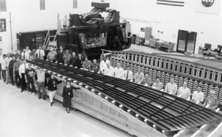
8.19 Lower cover panel used to demonstrate stitched/RFI composites technology. Note that the spar caps, ribs, and intercostal rib clips are all integral to the skin of this pane. At the time of fabrication, this was the largest integrally stiffened composite structure ever built in one piece.
It is important to note that, because stitches provide a highly redistributive way to transfer load, they do not require any additional structure to carry the very small stress concentrations caused by the stitch threads. Furthermore, because the number of stitches is at least one to two orders of magnitude larger than any amount of fasteners that would be used, there is far larger redundancy in load transfer between the two structures being joined. Indeed, this large redistribution in load changes local failure modes. In impact, the joint is more robust against impact than the remaining structure. By contrast, in bonded joints the most susceptible area for impact damage is the bonded joint because, in the bonded case, only resin (co-cured) or an adhesive (co-bonded) is available to carry load, whereas in the stitched case multiple high-strength stitch threads can transfer the load through the joint without any damage. And because this means that the impact occurs, by definition, on a larger mass (bonded stiffening element + skin vs. skin alone), the impact energy is better dissipated when the impact is centered beneath stiffening elements instead of between them.
Z-pinned joints
Another method to reinforce joints is the use of Z-pins. These are pre-cured, stiff pins or rods that are inserted either into a preform or, more typically, an uncured prepreg to provide out-of-plane reinforcement between plies. Like stitching, it is highly load redistributive and minimizes stress concentrations typically caused by fasteners. Partridge and Cartié [100] give an overview of Z-pinning, pointing out that Z-pins should be inserted prior to bagging in the case of autoclave cure of prepreg-based parts or just prior to resin injection in the case of liquid molding of Z-pinned preforms. For prepreg, the specific part preparation required for pinning was stated to be minimal, usually limited to a longer de-bulk phase in order to compact the laminate as close as possible to its final cured thickness. However, their conclusion fails to note two principal problems with Z-pinning. First, the insertion of the Z-pins can be quite time-consuming, especially for large parts. Second, specialized tooling must be used to insert Z-pins in parts with complex geometries. For these reasons, Z-pins have been used mainly in small- to medium-sized parts that are not overly complex. Partridge and Cartié do note that Z-pinning is not particularly suitable for the reinforcement of dry-fiber preforms unless the preform is stabilized by some means, such as a binder to facilitate both compaction and pinning. The benefits of Z-pins to improving fracture toughness is clearly shown in Fig. 8.20 [100] where both Mode I and Mode II fracture toughness are significantly improved with a sufficient loading of Z-pins. It is well known that improvements in Mode I improve joint strength, particularly pull-off loads, and that improvements in Mode II correlate strongly with improved impact-damage resistance.
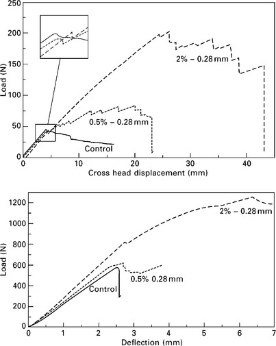
8.20 Load vs. displacement data showing the benefits of Z-pins to improve both Mode I fracture toughness via double cantilever beam (DCB, top) and Mode II fracture toughness via end notch flexure (ENF, bottom) specimens for a unidirectional carbon/epoxy. Note the increase in areas under the curve as the percentage of Z-pins is increased from 0 to 0.5 to 2% for both fracture modes [100].
The improvement in fracture toughness from Z-pins (as for stitching) is largely attributed to increasing fiber pull-out, which increases the amount of energy required for a crack to grow per unit area. Dai et al. [101] did work to establish a bridging law for Z-pins; the functional relationship between the delamination crack-opening displacement and the closure force from a single pin being the bridging law. Because Z-pin pull-out is a complicated process that is affected by many variables such as material properties, geometry, and interfacial parameters between the pin and the laminate, these must all be accounted for in any bridging law. In order to build their bridging law, Dai et al. needed accurate experimental data, which they generated themselves. Their results concluded the following:
1. At equal areal densities, small pins are more efficient than big pins.
2. Because single-pin orientation is difficult to control during pin insertion and because load–displacement alignment is almost impossible to obtain in single-pin pull-out tests, multi-pin tests are preferred to provide more reliable and accurate results.
3. In big-pin pull-out tests, the load drop caused by interfacial debonding is not as evident as in the small-pin tests because of the small difference between the initial debonding load and the initial frictional sliding load.
The first of these conclusions is the most important as it relates to improving damage toughness as it agrees with observations given above for stitching. The large load redistribution possible by having more, but smaller, out-of-plane reinforcements is clearly beneficial to providing a more damage-resistant structure. Additionally, as pin diameters grow, they become more and more like the fasteners they are meant to replace. Small pins at the same areal density, just like small stitches, will have far larger contact surface areas between the out-of-plane reinforcement than do larger pins, stitches, or fasteners. It is most likely that this very large increase in contact area accounts for a large portion of the improvement in fracture and pull-off loads from Z-pins and stitches. Extending this thinking further, it is also likely that, using the right type of out-of-plane reinforcement, further decreasing the size while maintaining the areal density will continue to provide benefits in improving damage tolerance.
Advanced preforms
The knowledge gained from understanding the roles of fiber, matrix, and out-of-plane reinforcements on improving damage tolerance is being used to create structures and structural concepts that have built-in damage tolerance features to leverage this knowledge. One recent structural concept is called PRSEUS [102] (for pultruded-rod-stiffened, efficient, unitized structure) shown in Fig. 8.21. This concept takes advantage of well-known mechanics principles like stiffening a structure by offsetting a stiff element (the pultruded rod) from the principal plane of bending (the skin) in a manner similar to an I-beam, but using a combination of composite materials, including a pultruded rod, closed-cell structural foam, a fibrous preform, and a matrix resin that is infused into the assembly and cured to make a part.
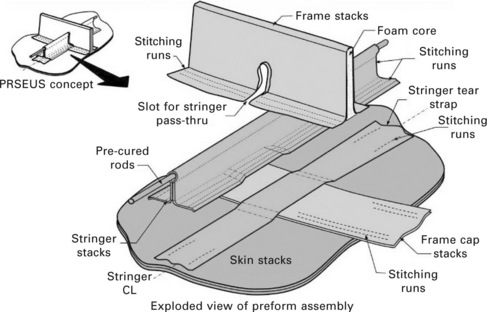
8.21 Schematic of PRSEUS (pultruded-rod-stiffened, efficient, unitized structure) [103].
Yovanof et al. [103] examine the potential for the use of PRSEUS to solve some of the structural and weight problems posed by aircraft with non-circular fuselages, such as the blended-wing body, shown in Fig. 8.22. In addition to targeting non-circular pressure vessels like a fuselage, the PRSEUS design shows some of the multifunctional capabilities of composites as the stitched design is inherently damage-arresting such that damage in one structural bay will not easily propagate to another. Furthermore, the linking of the stiffened sandwich stiffening elements allows for efficient load redistribution that further enhances damage tolerance. Li and Velicki [104] show that the type of structural concept shown in Fig. 8.22 can be tailored and optimized to exploit fully the orthotropic nature of carbon fibers and damage arrest design philosophies compared with existing composite designs and practices.

8.22 The X-48B Blended Wing Body flight research vehicle takes off in 2009 from Edwards Air Force Base, California, on a flight test. In March, the X-48B flight research team of Boeing, NASA and the US Air Force Research Laboratory successfully concluded the first phase of the aircraft’s flight test program, which started in 2007 and logged 80 flights. The aircraft is an 8.5 percent scale model of a heavy-lift, subsonic airplane with a 240 foot (73 meter) wingspan that possibly could be developed over the next 20 years for military applications such as aerial refueling and cargo hauling (Boeing Frontiers, May 2010, http://www.boeing.com/news/frontiers/archive/2010/may/May10_singles.pdf).
Dang et al. [105] present a method for the optimal design of unitized structures under damage tolerance constraints by considering both unitized structures with straight and curvilinear stiffeners. The objective of their study was to minimize the weight of the structure with constraint on static fracture strength, whereas panel thickness and stiffener sizes (height and thickness) are design variables. The study included damage-tolerance-based optimization of unitized structures with periodic boundary conditions to demonstrate the effectiveness of unitized structures, especially curvilinear-stiffened structures in terms of the load-carrying capacity in the presence of damage. The authors claimed that the method developed in the study could be used to optimize the unitized structure with static fracture strength or fatigue-life constraints coupled with buckling constraints to better exploit the effects of shape variables on the reduction of mass of the structure.
Scaling and hybrids
Ilcewicz [106, 107] discusses some of the issues regarding damage tolerance and the introduction of composites into primary aircraft structure. Scaling from small-scale test coupons to full-scale structures as well as scaling from small- to large-notch behavior are among the key scaling issues identified in furthering the use of composites in airframes. Fig. 8.23 shows the interrelationships of scaling steps and damage tolerance. It was noted that a number of factors, including damage size, spacing of stiffening elements (frames or stringers), and the ratio of skin to stiffening-element load sharing all will affect progressive damage growth, load redistribution, and structural failure.
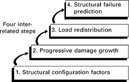
8.23 Damage tolerance analysis considerations [106].
Structural response is dependent on the type of damage, such as outlined in Table 8.1, which differentiates between damage that the structure should be able to withstand without repair and those types of damage that will require either minor or major repair. In certain cases, replacement of the damaged component will be preferred to repair. In all these cases, consideration of the likelihood and severity of the different categories of damage and the regulatory requirements [1] will guide the ultimate design. For example, in stiffened-skin designs, as mainly considered here, damage growth is dependent on the fracture behavior of the structure. In this case, for damage between stiffening elements, the damage growth will slow as the increased load redistributes into the adjacent stiffening elements. At this point, damage can proceed in several ways: the stiffening element may fail; the stiffening element may become detached from the skin; damage may propagate beneath the stiffener into another bay; or damage may be redirected along the stiffening elements. All of these, with the exception of the latter, which is typical of stiffening elements attached to skins via stitching or Z-pinning, typically result in catastrophic failure.
Table 8.1
Categories of damage and defect considerations for primary composite aircraft structure [105]
| Category | Examples (not inclusive of all damage types) |
| Category 1: Allowable damage that may go undetected by scheduled or directed field inspection (or allowable manufacturing defects) | BVID, minor environmental degradation, scratches, gouges and allowable manufacturing defects that must retain ultimate load for the specified life |
| Category 2: Damage detected by scheduled or directed field inspection at specified intervals (repair scenario) | VID (ranging from small to large), deep gouges, manufacturing defects/mistakes, major local heat or environmental degradation that must retain limit load until found |
| Category 3: Obvious damage detected within a few flights by operations focal (repair scenario) | Damage obvious to operations in a ‘walk-around’ inspection or due to loss of form/fit/function that must retain limit load until found by operations |
| Category 4: Discrete source damage known by pilot to limit flight maneuvers (repair scenario) | Damage in-flight from events that are obvious to pilot (rotor burst, bird-strike, lightning, exploding gear tires, severe in-flight hail) |
| Category 5: Severe damage created by anomalous ground or flight events (repair scenario) | Damage occurring due to rare service events or to an extent beyond that considered in design, which must be reported by operations for immediate action |
Different material combinations, in addition to their structural arrangement, may also affect damage tolerance behavior. Most often these material combinations are in the form of so-called hybrid composites made up of two or more different fiber types. Strictly speaking, many of the composites listed previously, like stitched or Z-pinned composites, are hybrids, but in the present context this will only refer to those with multiple fiber types or mixtures of fabric forms (e.g. braids, weaves, etc.). This section will also neglect nanocomposites-based hybrids as there are insufficient data to date to assess their ability to modify damage tolerance in aerospace composites. Lastly, as the focus of the present chapter is on polymeric composites, fiber-metal laminates like GLARE (glass-aluminum-reinforced epoxy) and ARALL (aramid-aluminum laminate) will likewise not be considered here.
Hybrids may be made from commingled yarns, e.g. Ref. [108], alternating layers of different fibers, e.g. Refs [109]–[111], or woven, non-woven, or braided materials containing two or more fiber types. Many of these hybrids for aerospace use glass-carbon, glass-aramid, or carbon-aramid combinations. It has been found in multiple instances that hybrids of glass and carbon can provide improved impact resistance, e.g. Refs [110] and [111], depending on the specific material combinations and lamination scheme. The different properties of the glass and carbon will also have an effect on other mechanical properties such that the improved damage tolerance may not provide the most cost-effective or weight-efficient design [109].
8.7 Conclusions
In considering damage in composite structures for aircraft, many parameters have been described above. A good summary of damage and its consequences is given by Ilcewicz [112], and Mohaghegh [113] describes how improvements in materials, manufacturing, and inspection methods have changed the design philosophy of aircraft. It is clear that, with the evolving nature of composite materials and the improvement in manufacturing methods, materials, and analytical techniques much more weight-efficient composite structures will be possible. However, the realization of these structures will require that the understanding of the interrelationships between materials, manufacturing, and testing be well understood.
It has been shown above that there is a wide variety of variables that must be considered in any composites-based design. In each case, it is up to the designer to identify potential damage modes based on expected damage sources (e.g. tool drop, hail impact, debris impact, ground-equipment damage, etc.) in order to satisfy the structural requirements outlined by regulatory bodies and from analyses of in-flight loads to design safe aircraft.
Some trends are emerging in aerospace composites. First and foremost, the amount of composites on aircraft is steadily increasing as shown in Fig. 8.24 [114] to the point where nearly half the structure of new, large commercial transports is made from composite materials. Barring unforeseen circumstances, this seems a trend that will continue.
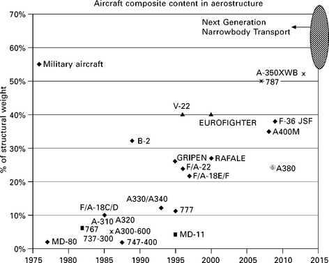
8.24 Growth in percentage of composite materials in both commercial and military aircraft structure since 1975 [114].
Second is the growth in automation as shown in Fig. 8.25, which shows an automated tape-laying (ATL) machine that dispenses prepreg tape onto a tool. Although the figure shows a flat plate, highly contoured parts, such as the Boeing 787 Dreamliner fuselage (see Fig. 8.26), can be fabricated using this technique and its close cousin, automated tow placement (ATP) in which much thinner prepreg segments are similarly laid down onto a tool. Automation is also present in the handling of composites. Automated ply cutters are used to cut prepreg and fabric alike. A summary of automated textile methods is given by Brandt et al. [117], including direct braiding of complex cross-sections and robotic stitching for automated preform assembly as shown in Fig. 8.27.
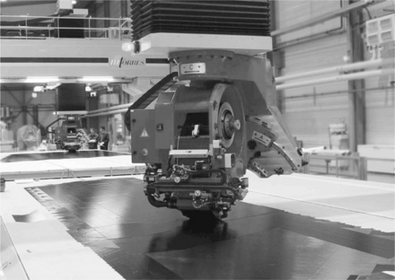
8.25 Automated tape-laying machine [115].
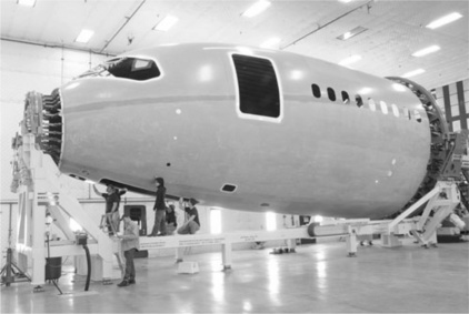
8.26 Forward section of Boeing 787 Dreamliner fuselage [116].
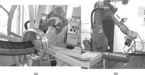
8.27 (a) Direct braiding of an I-beam cross-section. (b) Robotic single-sided stitching [117].
Third is the development of continuously improving modeling tools. In addition to analytical tools, such as finite-element analysis and computer-aided design that have been in use for many years, new tools for improving production flow, simulating assembly operations, and for designing fiber architectures are now sufficiently mature that they are more the norm than the exception in composites design. These new and improved tools in conjunction with improved automation machinery will allow for the cost-effective design and fabrication of structures that can take much better advantage of the anisotropy in composite materials to produce lighter-weight, more-durable structures. Additionally, molecular-dynamics tools are emerging that may allow for the tailored design of materials, but there is still much development required in this area before this may be realized on a large scale.
The fourth trend is the emergence of nanotechnology. It is still too early to state which of the large suite of potential nanotechnologies will be best suited for application to aerospace composites in the long run, but it is likely that these materials will be used to improve strength, damage tolerance, electrical and thermal transport properties. Exactly where these will be implemented and how they will be achieved is not yet known.
In all of these trends, the main goal for aerospace applications is improved performance (e.g. lighter-weight structures) with improved durability, manufacturability, inspectability, maintainability, and reparability. Except for the rare circumstance where a material substitution can improve performance without affecting the other parameters, achieving this goal will involve the simultaneous optimization of all of these.
One analysis tool that has not been mentioned thus far is the modeling of strength. There are well-known tools (e.g. rule of mixtures, Eshelby’s formula, etc. [5]) for calculating material moduli with a fairly high degree of fidelity. However, this is not the case for calculating strength and failure. It is the author’s opinion that all of the currently existing models for calculating strength are, to a large extent, based on ‘curve fitting’ or the ‘calibration’ of strength models such that they provide acceptable results. In essence, what these models require is a sufficiently large database of strength results that can be used in the model framework to allow for reasonably accurate calculations of structures that differ somewhat in geometry from the data present in the database.
Traditionally, strength determinations in aerospace have been made via ‘allowables’ testing, wherein a series of tests is conducted based on typical structural elements and subelements to determine the strength values (i.e. the allowable stress and strain levels) for such elements. These allowables values are then used to size and design the larger structures used in building aircraft, which are then validated through large-scale and, ultimately, full-scale, test articles. In many ways, the population of strength models with a robust database of coupon-level values is identical to the allowables approach, though it offers the promise of reduced testing costs in the long run by minimizing the number and types of mid-level tests that may need to be performed. However, before that can happen, sufficient testing will need to be performed to validate the strength models and their ability to accurately and reliably calculate large structure failures to give the design and certification communities enough confidence to use them to replace a significant portion of structural tests.
Improved strength calculations and inspection methods were discussed by Razi and Ward [15] who noted that structural damage design should be coupled with development of an aircraft maintenance plan in order to minimize both the frequency of in-service damage and repair costs. A schematic linking damage size (i.e. inspectability) to residual strength is shown in Fig. 8.28. It is the understanding of the link between these two that allows for damage-tolerant designs to be produced and validated. In this regard, allowables and certification test validation and analyses should address design ultimate strength, damage growth, residual strength, and maintenance issues for composite structures. Independent studies of design-ultimate-load or limit-load strength without data and analyses at intermediate load levels will not provide a balanced design that supports cost-effective maintenance such that a database that covers a range of damage scenarios of varying severity is needed to make intelligent decisions regarding damage-tolerant designs.
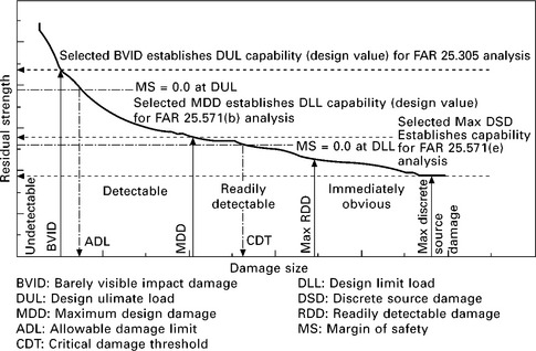
8.28 Comparison of residual strength vs. damage [11].
This chapter has outlined the requirements and types of in-service damage that must be considered in certifying an aircraft. As the sources of damage are unlikely to change, improvements in the damage tolerance of composite materials-based aircraft structures will come from improvements in a combination of materials, manufacturing methods, design concepts, and analysis methods as described above.
8.8 References
[1] Code of Federal Regulations, Title 14: Aeronautics and Space, FAR Part 25-Airworthiness standards: Transport category airplanes, Subpart C Structure, Federal Aviation Administration, Department of Transportation, Washington, DC.
[2] Stauffer, W.A., Lewold, J.G., Hoblit, F.M. Application of Advanced Methods to the Determination of Design Loads of the Lockheed L-1011 Tristar. AIAA Paper 72-775, AIAA 4th Aircraft Design, Flight Test, and Operations Meeting, Los Angeles, CA, August 7-9, 1972.
[3] Rouse, M., Jegley, D.C., McGowan, D.M., Bush, H.G. Utilization of the Building-Block Approach in Structural Mechanics Research. AIAA Paper 2005-1874, 46th AIAA/ASME/ASCE/AHS/ASC Structures, Structural Dynamics & Materials Conference, Austin, TX, April 18-21, 2005.
[4] Tsai, S.W., Hahn, H.T.Introduction to Composite Materials. Technomic Publishing Co., 1980.
[5] Christensen, R.M.Mechanics of Composite Materials. Dover Publications, 2005.
[6] Jones, R.M.Mechanics of Composite Materials. CRC Press, 1998.
[7] Tsai, S.W. Theory of Composites Design, 1992. [Think Composites].
[8] Whitney, J.M., Daniel, I.M., Pipes, R.B.Experimental Mechanics of Fiber Reinforced Composite Materials. Prentice-Hall, 1984. [Revised Edition, Society for Experimental Mechanics Monograph No. 4].
[9] Skudra, A.M., Bulavs, F.Y., Gurvich, M.R., Kruklinsh, A.A.Structural Analysis of Composite Beams. Technomic Publishing, 1991.
[10] Whitney, J.M.Structural Analysis of Laminated Anisotropic Plates. Technomic Publishing, 1987.
[11] ‘Standard Test Method for Compressive Residual Strength Properties of Damaged Polymer Matrix Composite Plates,’ ASTM Test Method D7137, ASTM International,
[12] Singh, A.K., Davidson, B.D., Eisenberg, D.P., Czabaj, M.W., Zehnder, A.T. Barely Visible Impact Damage Evaluation of Composite Sandwich Structures. AIAA Paper 2010-2770, 51st AIAA/ASME/ASCE/AHS/ASC Structures, Structural Dynamics, and Materials Conference, Orlando, Florida, April 12-15, 2010.
[13] Polimeno, U., Meo, M. Detecting barely visible impact damage detection on aircraft composites structures. Composite Structures. 2009; 91(4):398–402.
[14] Minakuchi, S., Okabe, Y., Mizutani, T., Takeda, N. Barely visible impact damage detection for composite sandwich structures by optical-fiber-based distributed strain measurement. Smart Mater. Struct.. 2009; 18:085018.
[15] Razi, H., Ward, S. Principles for Achieving Damage Tolerant Primary Composite Aircraft Structures. 11th DoD/FAA/NASA Conference on Fibrous Composites in Structural Design, Fort Worth, TX, August, 1996.
[16] Hedrick, I.G., Whiteside, J.B. Effect of Environment on Advanced Composites Structures. AIAA Paper 1977-463-14, AIAA Conference on Aircraft Composites: The Emerging Methodology for Structural Assurance, San Diego, CA, March 24-25, 1977.
[17] ‘Wildlife Strikes to Civil Aircraft in the United States 1990-2008,’ Federal Aviation Administration National Wildlife Strike Database. Serial Report; 15. Office of Airport Safety and Standards, Airport Safety, & Certification, Washington, DC, 2009. [Report of the Associate Administrator of Airports, September].
[18] Georgiadis, S., Gunnion, A.J., Thomson, R.S., Cartwright, B.K. Bird-strike simulation for certification of the Boeing 787 composite moveable trailing edge. Composite Structures. 2008; 86:258–268.
[19] MIL-STD-464Electromagnetic Environmental Effects Requirements for Systems. Department of Defense Interface Standard, 1997. [March 18].
[20] SAE Aerospace Recommended Practice 5414 Revision A – Aircraft Lightning Zoning. SAE International, 2005. [February].
[21] Feraboli, P., Miller, M. Damage resistance and tolerance of carbon/epoxy composite coupons subjected to simulated lightning strike. Composites Part A. 2009; 40:954–967.
[22] Ogasawara, T., Hirano, Y., Yoshimura, A. Composites Part A. 2010; 41:973–981.
[23] Hawley, A.V. Lightning Damage Protection for Composite Aircraft, 2009. [US Patent 7,554,785, June 30].
[24] Weitsman, Y. Stress assisted diffusion in elastic and viscoelastic materials. Journal of the Mechanics and Physics of Solids. 1987; 35(1):73–94.
[25] Campbell, F.C.Manufacturing Processes for Advanced Composites. Elsevier, 2004.
[26] Epstein, G., Ruth, S. Honeycomb Sandwich Structures: Vented Versus Unvented Designs for Space Systems, 1993. [NASA Report F04701-88-C-0089, October].
[27] Jackson, S.P., Weitsman, Y.Harrigan, Strife, Dhingra, eds. Moisture Effects and Moisture-Induced Damage in Composites. Proc. Fifth Int. Conf. on Comp. Mat. (ICCM V), 1985:1435–1452.
[28] Fang, G. Moisture and Temperature Effects in Composite Materials, 1986. [Texas A&M University Mechanics and Materials Center Technical Report MM5022-86-21, November].
[29] Li, J., Plotnikov, Y., Lin, W.W., Fang, X. Real-Time Monitoring of Microcrack Growth in Polymer-Matrix Composites During Temperature-Humidity Cycling. SAMPE Fall Technical Conference and Exhibition, Cincinnati, OH, October 29-November 1, 2007.
[30] Tsotsis, T.K. Effects of sub-freezing temperatures on graphite/epoxy composite materials. Transactions of the ASME, J. Eng. Mat. Tech.. 1989; 111:438–439.
[31] Kinard, D.A.The Structure of Water Adsorbed in Polymers. College Station, TX: Texas A&M University, 1981. [Ph.D. Dissertation, August].
[32] Franks, F.The Physics and Physical Chemistry of Water, Volume 1. Plenum Press, 1972.
[33] McKague, E.L., Jr., Halkias, J.E., Reynolds, J.D. Moisture in composites: the effect of supersonic service on diffusion. Journal of Composite Materials. 1975; 9(1):2–9.
[34] Collings, T.A., Stone, D.E.W. Hygrothermal effects in CFC laminates: damaging effects of temperature, moisture and thermal spiking. Composite Structures. 1985; 3(3-4):341–378.
[35] Adamson, M.J. A conceptual model of the thermal-spike mechanism in graphte/epoxy laminates. In: O’Brien T.K., ed. Long-term behavior of composites. American Society for Testing and Materials; 1983:179–191. [ASTM STP 813].
[36] Horrigan, D.P.W., Aitken, R.R. Finite Element Analysis of Impact Damaged Honeycomb Sandwich. 1999 LUSAS User Conference, CS503, Issue 1. Finite Element Analysis Ltd, 1999. http://www.lusas.com/pdf/CS503_FEA_of_Impact_Damaged_Honeycomb_Panels.PDF [Available at].
[37] Tsotsis, T.K., Lee, S.M. Characterization of Localized Failure Modes in Honeycomb Sandwich Panels Using Indentation. In: Deo R.B., Saff C.R., eds. Composite Materials: Testing and Design (Twelfth Volume). American Society for Testing and Materials; 1996:139–165. [ASTM STP 1274].
[38] Das, M., Oterkus, E., Madenci, E., Razi, H. Residual strength of sandwich panels with hail damage. Composite Structures. 2009; 88:403–412.
[39] Kim, H., Welch, D.A., Kedward, K.T. Experimental investigation of high velocity ice impacts on woven carbon/epoxy composite panels. Composites Part A. 2003; 34:25–41.
[40] Mahinfalah, M., Skordahl, R.A. The effects of hail damage on the fatigue strength of a graphite/epoxy composite laminate. Composite Structures. 1998; 42:101–106.
[41] Johnson, A.F., Holzapfel, M. Modelling soft body impact on composite structures. Composite Structures. 2003; 61:103–113.
[42] Kim, H., Kedward, K.T. Modeling hail ice impacts and predicting impact damage initiation in composite structures. AIAA Journal. 2000; 38(7):1278–1288.
[43] Weitsman, Y.J. Effects of fluids on polymeric composites – a review. In: Comprehensive Composite Materials. Elsevier; 2003:369–401.
[44] Sala, G. Composite degradation due to fluid absorption. Composites Part B. 2000; 31:357–373.
[45] Kriz, R.P. Influence of ply cracks on fracture strength of graphite/epoxy laminates at 76K. In: Wilkins D.J., ed. Effects of Defects in Composite Materials. American Society for Testing and Materials; 1984:250–265. [ASTM STP 836].
[46] Hartwig, G. Reinforced polymers at low temperatures. In: Reed R.P., Clark A.F., eds. Advances in Cryogenic Engineering – Materials Volume 28. Plenum Press; 1982:179–189.
[47] Kasen, M.B. Mechanical performance of graphite- and aramid-reinforced composites at cryogenic temperatures. In: Reed R.P., Clark A.F., eds. Advances in Cryogenic Engineering – Materials Volume 28. Plenum Press; 1982:165–177.
[48] Tsotsis, T.K. Thermo-oxidative ageing of composite materials. In: Martin R., ed. Ageing of Composites. Woodhead Publishing Ltd.; 2008:130–159.
[49] Accelerated Aging of Materials and Structures. Washington, DC: National Academy Press, 1996. [Committee on Evaluation of Long-Term Aging of Materials and Structures Using Accelerated Test Methods, National Materials Advisory Board, Publication NMAB-479].
[50] Ronk, W.R., Whiteker, S.M., Bullions, T.A., Kent, T.J. Thermal oxidative barrier coatings for organic matrix composite substrates and coated articles, 2008. [US206575: August 28].
[51] Ronk, W.R., Whiteker, S.M., Bullions, T.A., Kent, T.J. Methods for forming thermal oxidative barrier coatings on organic matrix composite substrates, 2008. [US213486, September 4].
[52] Shokrieh, M.M., Behrooz, F.T. Wing instability of a full composite aircraft. Composite Structures. 2001; 54:335–340.
[53] Kim, T.-U., Hwang, I.H. Optimal design of composite wing subjected to gust loads. Computers and Structures. 2005; 83:1546–1554.
[54] Qin, Z., Marzocca, P., Librescu, L. Aeroelastic instability and response of advanced aircraft wings at subsonic flight speeds. Aerospace Science and Technology. 2002; 6:195–208.
[55] Moosavi, M.R., Naddaf Oskouei, A.R., Khelil, A. Flutter of subsonic wing. Thin-Walled Structures. 2005; 43:617–627.
[56] Borglund, D., Kuttenkeuler, J. Active wing flutter suppression using a trailing edge flap. Journal of Fluids and Structures. 2002; 16(3):271–294.
[57] Pak, C., Li, W.W. Application of approximate unsteady aerodynamics for flutter analysis. AIAA Paper 2010-3085, 51st AIAA/ASME/ASCE/AHS/ASC Structures, Structural Dynamics, and Materials Conference, April 12-15, 2010. [Orlando, FL].
[58] DOT/FAA/AR-00/42, Aircraft Materials Fire Test Handbook, Federal Aviation Administration, Washington, DC. Available at: http://www.fire.tc.faa.gov/handbook.stm.
[59] FAA Advisory Circular AC 20-107AComposite Aircraft Structure. Washington, DC: Federal Aviation Administration, 1984. [April 25].
[60] Ochs, R.I., Hode, J.C. Composite Material Fire Fighting. Presented to International Aircraft Materials Fire Test Working Group, Köln, Germany, June 17. Federal Aviation Administration, Washington, DC, 2009. http://www.fire.tc.faa.gov/ppt/materials/June09Meeting/hode-0609-CompositeFuselageFirefightingWork.ppt [Available at].
[61] Webster, H.Fuel Fire Penetration Test and Destruction of a Transport Aircraft. Washington, DC: Federal Aviation Administration, 1996. [DOT/FAA/AR-96/48, December].
[62] Ochs, R.I. PIV Measurements on the FAA Fire Test Oil Burner. International Aircraft Materials Fire Test Working Group Meeting, October 21, 2009 http://www.fire.tc.faa.gov/pdf/materials/Oct09Meeting/Ochs-1009-PIV.pdf [Available at].
[63] Mueller, R., Huebner, R., Busch, H.-P., Wawrzyniec, M.-L. Burn through resistant aircraft, 2009. [WO2009118256, October 1].
[64] Heitkamp, R. High temperature 2000 °F burn-through resistant composite sandwich panel, 1995. [US5460864’ October 24].
[65] Schaefer, W., Schaut, G. Flame penetration blocker for fuselages, 1997. http://www.nbaa.org/ops/safety/hangar/aircraft-ground-damage-prevention.ppt [US5595817, January 21].
[66] http://www.nbaa.org/ops/safety/hangar/aircraft-ground-damage-prevention.ppt
[67] , Maintenance MattersFlying Safety. US Air Force, Safety Agency, 2004. [May].
[68] Wenner, C.A., Drury, C.G. Analyzing human error in aircraft ground damage incidents. International Journal of Industrial Ergonomics. 2000; 26:177–199.
[69] Scott, J.M., Phillips, D.C. Carbon fibre composites with rubber-toughened matrices. Journal of Materials Science. 1975; 10(4):551–562.
[70] Bascom, W.D., Bitner, J.L., Moulton, R.J., Siebert, A.R. The interlaminar fracture of organic-matrix, woven reinforcement composites. Composites. 1980; 11(1):9–18.
[71] Russell, A.J., Street, K.N. The effect of matrix toughness on delamination: static and fatigue fracture under mode II shear loading of graphite-fiber composites. In: Johnston N.J., ed. Toughened Composites. American Society for Testing and Materials; 1987:275–294. [ASTM STP 937].
[72] Groleau, M.R., Shi, Y.-B., Yee, A.F., Bertram, J.L., Sue, H.J., Yang, P.C. Mode II fracture of composites interlayered with polyamide particles. Composites Science and Technology. 1996; 56(11):1223–1340.
[73] Aksoy, A., Carlsson, L.A. Interlaminar shear fracture of interleaved graphite/epoxy composites. Composites Science and Technology. 1992; 43(1):55–69.
[74] Lee, S.-H., Noguchi, H., Kim, Y.-B., Cheong, S.-K. Effect of interleaved nonwoven carbon tissue on interlaminar fracture toughness of laminated composites: Part I – Mode II. Journal of Composite Materials. 2002; 36(18):2153–2168.
[75] Tsotsis T.K., Markus A., eds. AST Composite Wing Program Work Unit IV – Design, Analysis, and Manufacturing Studies. Long Beach, CA: The Boeing Company, 1999. [NASA/CR-1999-NAS1-20546, December].
[76] Larsson, F. Damage tolerance of a stitched carbon/epoxy laminate. Composites Part A. 1997; 28A:923–934.
[77] Jain, L.K., Dransfield, K.A., Mai, Y.-W. On the effects of stitching in CFRPs – II. Mode II Delamination toughness. Composites Science and Technology. 1998; 58:829–837.
[78] Sharma, S.K., Sankar, B.V. Effect of stitching on impact and interlaminar properties of graphite/epoxy laminates. Journal of Thermoplastic Composites. 1997; 10:241–253.
[79] Mouritz, A.P., Leong, K.H., Herszberg, I. A review of the effect of stitching on the in-plane mechanical properties of fibre-reinforced polymer composites. Composites Part A. 1997; 28A:979–991.
[80] Reeder, J.R. Stitching vs. a toughened matrix: compression strength effects. Journal of Composite Materials. 1995; 29(18):2464–2487.
[81] Hillermeier, R.W., Hayes, B.S., Seferis, J.C. Processing and Performance of Tackifier-Toughened Composites for Resin Transfer Molding Techniques. Proceedings, 44th International SAMPE Symposium, Society for the Advancement of Materials and Process Engineering, Covina, CA, 1999:660–669.
[82] Hillermeier, R.W., Seferis, J.C. Interlayer toughening of resin transfer molding composites. Composites Part A. 2001; 32:721–729.
[83] Kittelson, J.L., Hackett, S.C. Tackifier/Resin Compatibility is Essential for Aerospace-Grade Resin Transfer Molding. Proc. 39th International SAMPE Symposium, Society for the Advancement of Materials and Process Engineering, Covina, CA, 1994:83–96.
[84] Shih, C.-H., Liu, Q., Lee, L.J. Vacuum-assisted resin transfer molding using tackified fiber preforms. Polymer Composites. 2001; 721–729. [Dec].
[85] Hogg, P.J. Toughening of thermosetting composites with thermoplastic fibres. Materials Science and Engineering A. 2005; 412:97–103.
[86] Tsotsis, T.K. Interlayer toughening of composites. Polymer Composites. 2009; 30(1):70–86.
[87] Scholz, D.B., Dost, E.F., Flynn, B.W., Ilcewicz, L.B., Nelson, K.M., Sawicki, A.J., Walker, T.H., Lakes, R.S.Advanced Technology Composite Fuselage – Materials and Processes. Hampton, VA: National Aeronautics and Space Administration, Langley Research Center, 1997. [NASA CR 4731, April].
[88] Dost, E.F., Avery, W.B., Ilcewicz, L.B., Grande, D.H., Coxon, B.R.Impact damage resistance of composite fuselage structure. Hampton, VA: National Aeronautics and Space Administration, Langley Research Center, 1996. [NASA CR-4658].
[89] Dost, E.F., Avery, W.B., Ilcewicz, L.B., Coxon, B.R. Effects of stacking sequence on impact damage resistance and residual strength for quasi-isotropic laminates. American Society for Testing and Materials, 1991; 476–500. [ASTM STP 1110].
[90] Baluch, H.A., van Tooren, M.J.L., Schut, E.J. Design Tradeoffs for Fiber Composite Fuselages under Dynamic Loads using Structural Optimization. AIAA Paper 2008-2055-476, 49th AIAA/ASME/ASCE/AHS/ASC Structures, Structural Dynamics, and Materials Conference, April 7-10, 2008. [Schaumburg, IL].
[91] Lopes, C.S., Seresta, O., Coquet, Y., Gürdal, Z., Camanho, P.P., Thuis, B. Low-velocity impact damage on dispersed stacking sequence laminates. Part I: Experiments. Composites Science and Technology. 2009; 69:926–936.
[92] Hitchen, S.A., Kemp, R.M.J. The effect of stacking sequence on impact damage in a carbon fibre/epoxy composite. Composites. 1995; 26:207–214.
[93] Park, H.-J. Effects of stacking sequence and clamping force on the bearing strengths of mechanically fastened joints in composite laminates. Composite Structures. 2001; 53(2):213–221.
[94] Aktas, A., Dirikolu, M.H. The effect of stacking sequence of carbon epoxy composite laminates on pinned-joint strength. Composite Structures. 2003; 62(1):107–111.
[95] Ghiasi, H., Pasini, D., Lessard, L. Optimum stacking sequence design of composite materials. Part I: Constant stiffness design. Composite Structures. 2009; 90(1):1–11.
[96] Fuoss, E., Straznicky, P.V., Poon, C. Effects of stacking sequence on the impact resistance in composite laminates. Part 2: Prediction method. Composite Structures. 1998; 41(2):177–186.
[97] Todoroki, A., Ishikawa, T. Design of experiments for stacking sequence optimizations with genetic algorithm using response surface approximation. Composite Structures. 2004; 64(3-4):349–357.
[98] Irisarri, F.-X., Bassir, D.H., Carrere, N., Maire, J.-F. Multiobjective stacking sequence optimization for laminated composite structures. Composites Science and Technology. 2009; 69(7-8):983–990.
[99] Karal, M.AST Composite Wing Program – Executive Summary. Langley, VA: National Aeronautics and Space Administration, 2001. [NASA CR-2001-210650, March].
[100] Partridge, I.K., Cartié, D.D.R. Delamination resistant laminates by Z-Fiber® pinning: Part I manufacture and fracture performance. Composites Part A. 2005; 36:55–64.
[101] Dai, S.-C., Yan, W., Liu, H.-Y., Mai, Y.-W. Experimental study on z-pin bridging law by pullout test. Composites Science and Technology. 2004; 64:2451–2457.
[102] Velicki, A., Thrash, P.J. Composite Fabric with Rigid Member Structure, 2009. [US2009057487, March, 5].
[103] Yovanof, N.B., Velicki, A., Li, V. Advanced Structural Stability Analysis of a Noncircular, BWB-Shaped Vehicle. AIAA Paper 2009-2452, 50th AIAA/ASME/ASCE/AHS/ASC Structures, Structural Dynamics, and Materials Conference, May 4-7, 2009. [Palm Springs, CA].
[104] Li, V., Velicki, A. Advanced PRSEUS Structural Concept Design and Optimization. AIAA Paper 2008-5840, 12th AIAA/ISSMO Multidisciplinary Analysis and Optimization Conference, September 10-12, 2008. [Victoria, British Columbia, Canada].
[105] Dang, T.D., Kapania, R.K., Gurav, S.P. Optimization of Unitized Structures under Damage Tolerance Constraints. AIAA Paper 2009-2550, 50th AIAA/ASME/ASCE/AHS/ASC Structures, Structural Dynamics, and Materials Conference, May 4-7, 2009. [Palm Springs, CA].
[106] Ilcewicz, L.B. Composite Technology Development for Commercial Airframe Structures. In: Bader M.G., Kedward K.K., Sawada Y., eds. Chapter 6.08 in Comprehensive Composite Materials, Volume 6 Design and Applications. Elsevier Science, 2000.
[107] Ilcewicz, L.B. Past Experiences and Future Trends for Composite Aircraft Structure. Montana State University, 2009 http://www.coe.montana.edu/me/faculty/cairns/Composites/11-10-09li.pdf [presentation to, November 10, Available at].
[108] Thanomsilp, C., Hogg, P.J. Penetration impact resistance of hybrid composites based on commingled yarn fabrics. Composites Science and Technology. 2002; 63:467–482.
[109] Hosur, M.V., Adbullah, M., Jeelani, S. Studies on the low-velocity impact response of woven hybrid composites. Composite Structures. 2005; 67:253–262.
[110] Naik, N.K., Ramasimha, R., Arya, H., Prabhu, S.V., ShamaRao, N. Impact response and damage tolerance characteristics of glass-carbon/epoxy hybrid composites plates. Composites Part B. 2001; 32:565–574.
[111] Sayer, M., Bektas, N.B., Sayman, O. An experimental investigation on the impact behavior of hybrid composite plates. Composite Structures. 2010; 92:1256–1262.
[112] Ilcewicz, L.B. Composite Damage Tolerance and Maintenance Safety Issues. FAA Composite Damage Tolerance & Maintenance Workshop, Chicago, IL, July 19-21, 2006.
[113] Mohaghegh, M. Evolution of structures design philosophy and criteria. Journal of Aircraft. 2005; 42(4):814–831.
[114] Hexcel Corp. Annual Report 2007 and AeroStrategy Commentary, Annual Report 2007 and AeroStrategy Commentary. Material Wealth. 2006. [September].
[115] Black, S. Getting to know black aluminum, 2008. http://www.mmsonline.com/articles/getting-to-know-black-aluminum [MMSOnline.com, August, 10, Available at].
[116] , ATL and AFP: Signs of evolution in machine process control. High-Performance Composites. 2008 http://www.compositesworld.com/articles/atl-and-afp-signs-of-evolution-in-machine-process-control [September, Available at].
[117] Brandt, J., Drechsler, K., Filsinger, J. Advanced Textile Technologies for the Cost Effective Manufacturing of High Performance Composites. Proceedings, NATO RTO AVT Specialists’ Meeting on ‘Low Cost Composite Structures’, Loen, Norway, May 7-11. North Atlantic Treaty Organization, 2003. [Research and Technology Organization, RTO-MP-069(II), May].