Progress in failure criteria for polymer matrix composites: A view from the first World-Wide Failure Exercise (WWFE)
Abstract:
This chapter gives an account of the predictive capabilities of 19 failure criteria for two-dimensional (2D) stress analysis of composite laminates. It is based on the first phase of an activity, called the ‘World-Wide Failure Exercise’ (WWFE-1). The originators of failure theories provided an up-to-date description of their models and their correlations with relevant experimental results. Areas are highlighted where those criteria have shown a lack of consensus. The chapter provides a clear way forward through the co-ordination of two new exercises: WWFE-2 (dealing with failure under 3D (triaxial) loadings) and WWFE-3 (dealing with matrix cracking, damage and continuum mechanics).
1.1 Introduction
Undoubtedly, the use of fibre-reinforced composites (FRCs) materials in aerospace, space, land and sea applications has been growing steadily. All the signs indicate that the spread may have not yet reached its peak, although some of the current aircraft are made of composites covering up to 50% of their weight. One of the main challenges facing the structural design community is the need to predict the response of fibre-reinforced composites under complex loading. ultimately, designers of composite structures require robust tools or predictive methodologies and such tools should be accurate, fully benchmarked and their limits of applicability should be clearly defined. This is attributed to the fact that there is a growing realisation that ‘make and test’ philosophy is simply too slow and too costly, especially for cases involving bringing new components to the marketplace. The use of failure criteria is essential for carrying out design activities without resorting to prolonged and expensive experimental programmes. Hence, and for a long time, failure criteria for composites have been receiving a great deal of attention by the composite community.
Unfortunately, progress and success in developing robust failure criteria have been slow and relatively limited. Historically, within the academic community, there has been a steady stream of work, starting in the 1950s, investigating modelling of failure of composite materials. The literature in this domain contains many publications, from many sources, that offer techniques with the potential for development into composite design tools of varying degrees of sophistication. Numerous attempts have been conducted dealing with comparisons between competing theories and between theory and experiment, and they generally take one of two forms:
• Form 1: An author produces a computer program which contains a personal interpretation of a range of failure theories, devised by others and gleaned from the literature. In certain cases, the author has introduced a genuinely new theory of his/her own or a modification to someone else’s theory. The program is then used to generate failure predictions, usually over a restricted range of materials, layup configurations and loading conditions. Conclusions are then drawn as to the validity or otherwise of the competing theories.
• Form 2: An author conducts experiments to measure the strength of a series of laminates. By necessity, the experiments cover a restricted range of materials, layup configurations and loading conditions. The author then takes the approach outlined above to generate theoretical predictions for comparison with the experimental data. Frequently, in the light of the available experimental data, the author introduces modifications (‘tuning’) to one or more of the theories which improve the fit between theory and experiment. Conclusions are then drawn as to the validity or otherwise of the competing theories.
Neither of these two forms has satisfied a true and an impartial benchmarking of existing theories. Furthermore, even if it had, there has been no independent benchmarking that enables the competing methodologies to be compared. Hence, it is obvious that there is a real drive and urgent requirement to carry out such a comparison.
In summary, it can be said that the way in which the previous studies were carried out has meant that no clear consensus has been established on the best models and failure criteria that can be used reliably by designers of lightweight fibre-reinforced polymer composites structures. However, the literature remains full of potential approaches and theoretical methods and a mechanism of distilling their goodness and richness is needed.
1.2 Aims of the first World-Wide Failure Exercise (WWFE)
The lack of an impartial benchmarking process has prompted the authors to carry out a rigorous international study to describe the status, the accuracy and the bounds of validity of the current theoretical methods. The authors have organised and co-ordinated what is currently known as the ‘World-Wide Failure Exercise’ (WWFE), with the following principal aims in mind:
(I) Establishing the current level of maturity of theories for predicting the failure response of fibre-reinforced plastic (FRP) laminates under in-plane (i.e. 2D) loadings.
(II) Closing the knowledge gap between theoreticians and design practitioners in this field.
(III) Stimulating the composites community into providing design engineers with more robust and accurate failure prediction methods, and the confidence to use them.
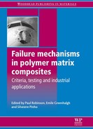
The plan for completing the benchmark process is illustrated in Fig. 1.1. It involves carrying out the activity in a number of distinct stages, referred to as Stage I, Stage II and Stage III. These are described below; see also Hinton et al. (2004) for full details of the WWFE.
1.1 A diagram showing the process adopted in the World-Wide Failure Exercise. (Hinton et al., 2004)
1.2.1 Stage I: establishing a framework
During this stage, a number of steps are taken, as detailed in the top box of Fig. 1.1. At the end of this stage, a list of potential participants is established. Also, a data-pack defining the challenging problems and a draft of instructions to be issued to participants for Part A are prepared.
1.2.2 Stage II: part A
During this phase, recognised experts in the area of fibre composite failure theories, including leading academics and developers of software/numerical codes, have agreed to take part and comply with the format and the set of instructions and guidelines issued in the invitation letter. The participants submit Part A papers providing ‘blind’ theoretical predictions for specified cases are received by the organisers. The papers are subjected to a stringent reviewing process. The organisers then make a comparison between the blind theoretical predictions and publish all the papers in a journal.
1.2.3 Stage III: part B
This stage is designed to make a comparison between the predictions from Part A and available experimental results. The stage runs as follows:
• Provide full set of experimental results for each case and describe the experiments.
• Issue of datapack 2 and instruction to authors.
• Participants submit their Part B paper to organisers:
– describing the correlations between their Part A theoretical results and experimental results;
– suggesting possible refinement to theory, reasons for differences and a set of recommendations, based on the participants’ experience.
• The submissions are subjected to a stringent reviewing process.
• The organisers make a comparison between theories and experiments and publish all the Part B papers in a journal. The organisers highlight the strengths and weaknesses of both the individual criteria and the whole set of available criteria as the experimental results.
1.3 Setting up test problems
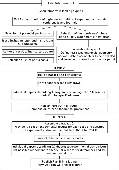
Careful consideration was given to this step in order to ensure that the test problems would provide a thorough examination of the theories, with high-quality experimental data available so that the theories could be benchmarked against reality. Fourteen cases were identified, providing a test of the capabilities of the theories to predict stress–strain response, strength and modes of failure for a range of materials, layup geometries and load ratios. These test cases are listed in Table 1.1 and a definition of the loading patterns applied to a general multi-directional laminate is sketched in Fig. 1.2.
Table 1.1
Details of the laminates and loading (test) cases used in the first exercise (WWFE-1)
| Test case | Laminate layup and material | Description (a wide range of biaxial stress ratios unless otherwise indicated) |
| 1 | 0 ° E-glass/LY55 | Biaxial failure stress envelope under (σy versus τxy) |
| 2 | 0 ° T300/914C | Biaxial failure stress envelope (σx versus τxy) |
| 3 | 0 ° E-glass/MY750 | Biaxial failure stress envelope (σy versus σx) |
| 4 | (90 °/±30 °/90 °) E-glass/LY556 | |
| 5 | Biaxial failure stress envelope (σy versus σx) Biaxial failure stress envelope (σx versus τxy) |
|
| 6 | (0 °/±45 °/90 °) AS4/3501-6 | Biaxial failure stress envelope (σy versus σx) |
| 7 | Stress–strain curves under σy : σx = 1 : 0 | |
| 8 | Stress–strain curves for σy : σx = 2 : 1 | |
| 9 | ±55 ° E-glass/MY750 | Biaxial failure stress envelope (σy versus σx) |
| 10 | Stress–strain curves under σy : σx =1 : 0 | |
| 11 | Stress–strain curves for σy : σx = 2 : 1 | |
| 12 | (0 °/90 °) E-glass/MY750 | Stress–strain curve under σy : σx = 0 : 1 |
| 13 | ±45 ° E-glass/MY750 | Stress–strain curves for σy : σx = 1 : 1 |
| 14 | Stress–strain curves for σy : σx = 1 : −1 |
1.2 Lamina and laminate coordinates and loading configurations: (a) unidirectional lamina, (b) off-axis lamina and (c) multi-directional laminate. Directions 1: fibre direction, 2: transverse direction, 3: through-thickness direction. Directions x, y and z are global directions. θ is an angle representing fibre orientation relative to × direction.
Selecting the laminates and loading conditions to be analysed was quite challenging. The following factors were taken into consideration:
• The test cases should include laminates that are of practical use. For this matter, laminates used in aircraft, pressure vessels, struts and space were included.
• The problems should cover a wide range of layups, starting from a lamina to a laminate. For this reason, six different layups were chosen and these are (0 °), (90 °/±30 °/90 °)s, (0 °/±45 °/90 °)s, (±55 °)s, (0 °/90 °)s and (±45 °)s laminates where the subscript s denotes symmetric.
• A wide range of loading conditions should be analysed. The cases selected included generating the complete failure envelopes under combined stresses (σy versus σx), (σy versus τxy) or (σx and τxy).
• The problems should include predicting the stress–strain curves under both uniaxial and biaxial loading because changes in laminate stiffness may be critical in some applications.
• The laminates analysed should be capable of developing different types of damage due to loading in shear, tension and compression, transverse and parallel to the fibre direction.
• Both linear and non-linear behaviours of unidirectional laminae should be considered.
• Experimental results should be available that could be used to check the effectiveness of the theoretical predictions
In order to avoid any ambiguity in interpretation between the participants, the organisers produced ‘datapack 1’ that defined the test cases in great detail. It was important to ensure that each participant started from identical descriptions of the test problems and materials properties to be used in the calculations. Similarly, to ensure that the predictions of each participant could be compared directly, the organisers provided detailed specifications of the parameters to be predicted, down to the level of the axes and scales for each graph.
Fourteen test cases covering six layups were selected for analysis and benchmarking and Table 1.1 summarises laminate type, material type and the graphical results requested.
1.4 Description of available models
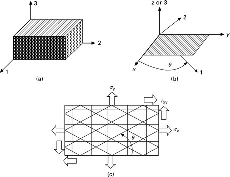
The first exercise was to identify recognised experts in the area of fibre composite failure theories, including leading academics and developers of software/numerical codes, who agreed to participate and submit Part A and Part B papers to a strictly controlled format. Table 1.2 shows the participants’ names and the methods they represented, where a total of 15 different groups have presented 19 different methodologies. A brief summary of these methodologies is shown in Table 1.3. It was noted that some of the theories were labelled as (A) and (B) in situations where the theory that was applied in Part A was modified in Part B.
Table 1.3
Brief description of the approaches of the originators of failure theories represented in WWFE-1
| Model no. | Description |
| 1 | Bogetti et al. (2004a, 2004b) employed the maximum strain theory in a full 3D form, taking into consideration the nonlinear shear stress–strain response of the lamina. |
| 2 | Chamis’ theory (see Gotsis et al., 1998, 2002) has developed two computer programs: (a) Integrated Composite Analyser (ICAN) and (b) Composite Durability Structural Analyser (CODSTRAN) which has been integrated with a finite element package that allows analysis of complex structures. Results are presented from each program. Both of Chamis’ programs are based on micromechanics relationships that predict the lamina properties from those of the constituent fibre and matrix. |
| 3 | Cuntze’s theory (see Cuntze and Freund, 2004; Cuntze, 2004) gains many of its strong features from that of Puck (see Puck and Schürmann, 1998, 2002). It considers five failure mechanisms (two fibre failure and three inter-fibre failure) and its predictions of the three failure envelopes for the unidirectional laminae bear some resemblance to Puck’s. Unlike Puck’s theory, interaction between the failure mechanisms is assumed, due to probabilistic effects. |
| 4 | Eckold (1998, 2002) demonstrated a simplified approach which is employed in the British design code for glass fibre reinforced tanks and pressure vessels. The code was intended primarily for designing plant for the chemical and process industry and applies stringent limits on strain to avoid resin cracking and resin/fibre debonding. |
| 5 | Edge (1998, 2002) presented an approach that has been developed by one of the major aerospace companies. The method makes allowance for nonlinearity, assuming that failed plies unload gradually (in contrast to the abrupt ‘ply discount’ technique). A number of lamina failure criteria are utilised (maximum stress, interactive failure between transverse tension and shear, and interaction between longitudinal compressive stress and shear stress), the choice being dependent on the biaxial stress state encountered during the analysis. |
| 6 | Hart-Smith (1998a, 1998b, 2002a, 2002b) provided three contributions: (a) a Generalized Tresca model which considers shearing of the fibres as one of the dominant failure modes; (b) a 2D interpretation of the widely used maximum strain and truncated maximum strain failure theory with a simplifying assumption to suppress the occurrence of initial failure; and (c) a generalisation of Hart-Smith’s well-known Ten-per-cent rule, which has been used quite widely in the aerospace industry for many years. |
| 7 | Huang (2004a, 2004b) provided a theory which is micromechanics-based and it combines a number of ideas (bridging model, anisotropic plasticity and generalised maximum stress theories) into a single theoretical framework. The theory provides a basis for obtaining the lamina and laminate moduli and strengths from the constituent fibre and matrix properties. |
| 8 | Mayes and Hansen (2004a, 2004b) have developed a finite element, multi-continuum, micromechanics based theory that takes the lamina nonlinear shear behaviour into account. The theory employs a form of interactive failure criterion at the fibre and matrix constituent level and it uses a finite element method to calculate values of stress at the laminate level. |
| 9 | McCartney (1998, 2002) employed an analysis based on damage mechanics. He used a fracture energy based approach to predict the formation and multiplication of transverse tensile cracks as a function of applied strain. The progressive reduction in laminate stiffness due to the presence of the transverse cracks is then predicted. |
| 10 | Puck (see Puck and Schürmann, 1998, 2002) has been working for almost 30 years to develop a mechanistic theory that distinguishes between various modes of failure. Puck’s theory employs two independent fracture criteria (for fibre fracture and inter-fibre fracture) and makes allowance for a continuous and gradual loss of stiffness after initiation of cracking. Puck generously acknowledged Hashin’s contribution to his type of approach. |
| 11 | Rotem (1998, 2002) provided a contribution which is based on a theory developed in an earlier collaboration with Hashin. It is one of the earliest to concentrate on two separate failure criteria, one for the fibres and the other for the resin. |
| 12 | Sun and Tao (1998) and Sun et al. (2002) presented results from two separate analytical routes, one linear and the other nonlinear. The linear analysis, which employs a derivation of the Hashin–Rotem lamina failure criteria, was applied to generate the failure envelopes and stress–strain curves. The detailed nonlinear analysis, which is based on finite element analysis and allows for elastic/plastic material properties and progressively increasing matrix crack density, was used in the test cases involving prediction of stress–strain curves. |
| 13 | Tsai (see Liu and Tsai, 1998 and Kuraishi et al., 2002) has been associated with the development of failure theories for polymer composites for more than 30 years. He is a strong advocate of the quadratic failure criterion with linear terms (the Tsai–Wu failure criterion) because (i) it is easy to use, (ii) it is a single valued function, (iii) it is based on a mathematically rigorous framework, and (iv) it gives a basis for an extension to cater for three-dimensional failure cases. The theory, which he employed in the failure exercise, has been used widely and has been disseminated to the community in the form of a spreadsheet-based computer program. |
| 14 | Wolfe and Butalia (1998) and Butalia and Wolfe (2002) employed a strain energy based failure theory which originates from the work of Sandhu and colleagues at Wright Patterson Air Force Base during the early 1970s. |
| 15 | Zinoviev et al. (1998, 2002) presented the widely used maximum stress theory. Their theory has been highly developed and takes into consideration such factors as the unloading behaviour of cracked laminates, and geometric nonlinearity due to changes in ply angle with increasing deformation. |
1.5 Design problems solved
The results from WWFE-1 proved to be a groundbreaking effort with many achievements:
• It established, for the first time, an open and objective way of working in order to compare, contrast and challenge disparate theories from around the world.
• It exposed the strengths and weaknesses of the current theories.
• It provided a stimulus for researchers to build upon the accurate theoretical features whilst making improvements to deal with the shortfalls that were exposed.
• It highlighted gaps in experimental data and in theoretical understanding, and preliminary recommendations were made in terms of prioritisation and approach to their resolution.
• It provided design engineers (the ultimate customers for such research knowledge) with recommendations on the preferred theories to use, together with evidence of the level of confidence and bounds of applicability.
The results from the first exercise have helped in solving a number of design problems. A list of the major issues addressed in the exercise is shown in Table 1.4. In order to illustrate the diversity in the predictions, the results from two of the test cases are described below.
Table 1.4
List of the major issues addressed in the exercise (WWFE-1). The test cases are those listed in Table 1.1
| Test case | Issues to be addressed |
| 1-14 | Use of micromechanics for prediction properties/failure |
| 1-3 | Prediction of the biaxial failure of a lamina in isolation |
| 4-14 | Prediction of various modes of failure |
| 4-7 | Prediction of the whole laminates failure envelopes |
| 4-14 | Matrix failure in tension, shear and compression |
| 4-14 | Single material nonlinearity |
| 4-14 | Post-failure modelling or degradation of composite |
| 4-7 | Prediction of fibre failure |
1.5.1 Examples of predictions of selected cases
In this section, two tests cases, described in Table 1.1, are selected to illustrate the degree of correlation between the failure criteria and experimental data. These are Test case 3 and Test case 12, representing the biaxial behaviour of a unidirectional lamina under direct stresses and the uniaxial tensile stress–strain curves of a crossply (0 °/90 °)s laminate.
Test case 3
This is a unidirectional 0 ° E-glass/MY750 subjected to biaxial failure stresses along the fibres (σx) and transverse to the fibre direction (σy). This test case illustrates how the theories are formulated on a lamina level to predict failure, where, generally, initial and final failure strengths are coincident. The test data were obtained from testing hoop wound thin tubes under combined internal pressure and axial loading, where the application of the internal pressure leads to the creation of tensile stress along the fibre direction (see Hinton et al., 2004).
A comparison between the various failure models and experimental data is shown in Fig. 1.3. The data covered one part of the envelope as there was a lack of data in the other parts. It should be noted here that some of the models were labelled as ‘A’ and ‘B’. This labelling reflects the reality that some of the theories were modified in Part B of the exercise. A number of observations may be made:
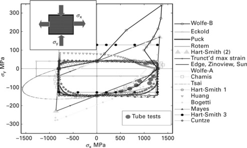
1.3 Comparison between the theoretical predictions of 19 failure criteria and test data for Test case 3 in the first exercise (WWFE-1).
• Some of the theories, such as the theory used by Zinoviev et al. (1998, 2002), assumed that the strength in one direction was independent of the magnitude of applied stress in the other directions.
• Bogetti et al.’s (2004a,b) model does not give a unique prediction for the uniaxial compression strength parallel to the fibres where two values for the uniaxial compression strength were plotted. Similarly, Wolfe and Butalia (1998) and Butalia and Wolfe (2002) produced a discontinuous envelope as the stresses approach uniaxial tension as well as uniaxial compression along the fibre direction (i.e. at σx : σy = 1 : 0 and −1 : 0).
• Some theories predicted envelopes in which the effective strength in one direction is influenced by the applied stress in the other direction. These theories include Tsai, Rotem, Sun, Wolfe, Cuntze, Mayes, Bogetti and Huang. Tsai’s theory predicted a large enhancement in the longitudinal compressive strength in the σy–σx space. It is a feature of his equation that the predicted biaxial compressive strength increases when the value of the uniaxial transverse tensile strength is reduced.
• Hart-Smith-2 and Bogetti predict a significant linear enhancement in the strength under certain ranges of biaxial tension–tension and compression–compression stress states in σy–σx space.
• One of the most common forms of interaction assumed that combined stresses reduced the strength of a lamina to a value lower than its uniaxial strength; see the theories by Rotem, Sun, Huang, Mayes, Cuntze and Wolfe. In the tension–tension quadrant, Huang predicts stress interaction that suppresses the strength by more than the other theories.
In can be seen that, although there were some similarities between the predictions, no two theories gave identically-shaped envelopes for this test case. It is worth pointing out here that the exercise did not include cases for studying how the failure envelopes shown above are affected by the application of a through-thickness stress component (σz). This represents one of the gaps identified in the exercise; see Section 1.7.1 for gaining insight into how this and other gaps are being solved.
Test case 12
This describes the behaviour of (0 °/90 °) E-glass/MY750 under uniaxial tension σy : σx = 0 : 1. This test case illustrates how the failure criteria are used to predict various modes or stages of failure and where initial failure takes place well before final failure occurs. The behaviour of this laminate is thought to have been understood in the 1970s where matrix cracks development was studied experimentally by many investigators.
The test data were obtained by testing coupon specimens using a tensile testing machine. The stress–strain curves were obtained from the load measured by the machine and from the strain gauges attached to the surface of the coupon. The strain gauges measured the strains in the loading direction and in the transverse direction. The experimental results indicated that the failure in the laminate took place in three stages:
• Stage I: Initial failure by matrix cracking in the 90 ° plies.
• Stage II: Intermediate failure by longitudinal splitting in the 0 ° plies.
• Stage III: Final failure by fibre tension failure in the 0 ° plies.
Stages I and II are depicted in Fig. 1.4. Photographs showing the third mode of failure are not shown. The horizontal lines represent matrix cracking in the 90 ° plies and the vertical lines indicate fibre splitting in the 0 ° plies.
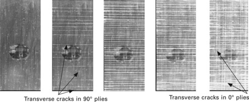
1.4 Photographs showing failure progression in (0 °/90 °) glass/epoxy (GRP) laminate under uniaxial tension.
The measured failure stresses corresponding to these three modes are 117 MPa, 402 MPa and 609 MPa, respectively. The measured stress–strain curves exhibited a change in the slopes at the first and second modes of failure.
Figure 1.5 shows a comparison between the failure theories and test data for the three observed modes of failure. The vertical axis shows the ratio of predicted to measured strength and the horizontal axis represents the theory used. The lower graph shows the initial failure (failure of the 90 ° plies) prediction and the middle and the top graphs represent the intermediate (splitting of the 0 ° plies) and final (fibre tension of the 0 ° plies) failure predictions. It is clear that the majority of the models predicted lower initial failure stress in comparison with test data. It was striking that only a few models predicted the intermediate failure mode whereas the majority of the models were able to predict the final strength relatively well.
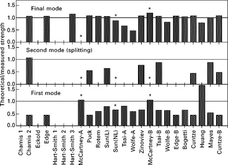
1.5 Comparison between the various failure models used in WWFE-1 for the prediction of failure in Test case 12. Theories with (*) are those employed models predicting matrix crack density in the laminate. Note that only a few theories predicted the second mode (splitting) of failure.
It was noted from comparing the theoretical predictions that, although the predicted stress–strain curves are superficially rather similar, a close examination of the results revealed striking differences. For example, the transverse failure strain εy (i.e. perpendicular to the loading direction) ranged from +0.05% (Sun (L)) to −0.776% (Rotem). This large difference between the failure strains reflects the differences in the post-failure analysis adopted. Bearing in mind that the measured failure strain is −0.125%, the theoretical results of Rotem and Sun(L) showed a significant large deviation from the experimental data.
The predicted final failure stresses were in the range of 293–714 MPa with most of the failure theories predicting final failure by tensile fracture of the fibres in the 0 ° layers at a laminate stress of around 640 MPa. The final failure loads predicted by Huang, Tsai and Wolfe were lower than the others and the corresponding strains in the loading direction were also lower, with Wolfe’s method predicting strains that were 50% that obtained from the majority of the methods.
It was also noted that only two of the models used (McCartney and Sun(NL)) were capable of dealing with transverse matrix cracking where crack density may be predicted as a function of the applied stress. However, McCartney did not attempt to predict final failure and terminated the curves at an arbitrary point. In addition, only two of the 14 test cases were solved by McCartney’s theory.
The strengths and weaknesses of damage, fracture and continuum mechanics theories were not fully explored or assessed in this exercise. In fact, these are some of the fundamental areas where gaps were identified as a result of completing the first exercise. See Section 1.7.2 for more details of the current activities that are aimed at rectifying this problem.
1.6 Gaps identified
Two high-priority gaps were identified in WWFE-1 and those are related to
1. Triaxial failure behaviour of composites under 3D stresses.
2. Advanced models based on damage, cracking and continuum mechanics principles.
The first priority gap is related to the need to examine the fidelity of failure theories when applied to components under 3D (i.e. triaxial) states of stress. Such stress states are commonly induced in thick composite components (e.g. rotor blades, pressure vessels), during impact and ballistic conditions or as a result of stress concentrations (e.g. in bolted joints). In order to meet this need, the authors launched a second World-Wide Failure Exercise (WWFE-2), with the objective of extending the assessment of predictive failure criteria from 2D to 3D states of stress.
The second priority gap will deal with validating and benchmarking failure theories that are capable of predicting damage, such as matrix crack initiation and development, delamination initiation triggered by transverse cracks, and deformation up to final fracture. Damage levels and damage modes are very important in the final optimisation of lightweight composite components and in the prediction of leakage in pressurised vessels and stability of thin and thick composites. Furthermore, life evaluation and fatigue behaviour of composites normally require a well-founded knowledge of the way that different modes of failure develop at various stages of loading cycles during service. The authors have co-ordinated a third activity, called the third World-Wide Failure Exercise (WWFE-3), to assess the capability of current models dealing with these contentious issues.
1.7 Current activities
Both the WWFE-2 and WWFE-3 are being run in two parts, building upon and employing the principles established during WWFE-1. Part A is devoted to providing full details of the theoretical models and failure criteria of the participants and Part B is concerned with comparing the theoretical results with experimental results.
1.7.1 The second World-Wide Failure Exercise
Aims
The first exercise highlighted a number of areas where current modelling capabilities have not been validated or benchmarked. These are listed as follows:
1. Applicability of composite failure criteria to isotropic materials.
2. Effects of pressure on strength and deformation of multi-directional laminates.
3. Effects of 3D stresses on the failure of multi-directional laminates.
4. 3D elastic constants of multi-directional laminates.
5. Effects of layup on through-thickness strength of laminates.
6. Failure under combined direct through-thickness and shear stresses of laminates.
The second exercise was launched with the following aims in mind:
• Solve specific gaps identified in WWFE-1.
• Extend the philosophy used previously to include 3D failure criteria.
• Identify well-established champions of triaxial (3D) failure criteria.
• Validate and benchmark their models.
• Identify any gaps in the current triaxial models.
• Identify specific shortfalls in experimental data/test results.
• Stimulate the composites community to provide better tools.
• Provide designers with guidance for predicting accurate strength under 3D states of stress.
Test cases
The test cases in WWFE-2 were chosen carefully to stretch each theory to the full in order to shed light on their strengths and weaknesses. They focused on a range of classical, continuous fibre, laminated, and reinforced polymer composites subjected, in the absence of stress concentrations, to a variety of triaxial loading conditions. The key issues being explored were:
• The means by which the theories distinguish (if at all) between the effects of anisotropy and heterogeneity.
• The types of failure mechanism employed and the way that each is implemented within any given theory.
Twelve test cases were identified for the purpose, involving five layups: a base resin with isotropic properties, a unidirectional lamina, a crossply laminate, an angle ply laminate and a quasi-isotropic laminate. These were made from six different fibre/matrix combinations: an epoxy, T300/epoxy, E-glass/epoxy, S-glass/epoxy, A-S carbon/epoxy and IM7/8551 materials. Full details of the test cases are provided by Kaddour and Hinton (2012).
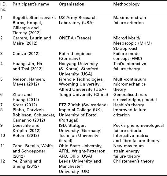
Methodologies used
Twelve leading, and internationally recognised, groups have taken part in the WWFE-2 by employing their methods to solve 12 challenging test cases. The names of these participants and the methodologies they employed are listed in Table 1.5. The methodologies cover a wide range of approaches including: micro-mechanics, phenomenological models, simple maximum strain model and strain energy method.
1.7.2 The third world-wide failure exercise
The second gap that was identified in the first exercise was the assessment of advanced models based on damage, cracking and continuum mechanics principles.
Aims
There are a large number of aims that WWFE-3 is attempting to resolve. In particular, the first exercise has shown that following areas are not well understood:
1. Damage and delamination initiation and evolution.
2. Matrix crack initiation and crack density evolution.
3. Effects of ply thickness, ply constraint and ply stacking sequence.
4. Cracking under bending and under thermal loading.
5. Monotonic loading, unloading and reloading.
6. Failure at stress concentration (e.g. open hole).
7. Size effects, statistical and probabilistic nature of failure.
Consequently, the third exercise (WWFE-3) was launched with the following aims in mind:
• Solve specific gaps identified in the first WWFE.
• Extend the philosophy used previously to include damage, fracture and continuum mechanics models for composites.
• Identify champions of damage, cracking and continuum mechanics.
• Validate and benchmark their models.
• Identify any gaps in the current models.
• Identify specific shortfalls in experimental data/test results.
• Stimulate the composites community to provide better tools.
• Provide designers with guidance for predicting damage and fracture.
Test cases
Test cases for WWFE-3 were selected so that the laminates analysed exhibit various damage processes involving some of the following areas: a single mode of damage, multiple modes of damage, transverse tension-dominated, shear-dominated and mixed mode matrix cracking, ply staggering and thickness effects, effects of ply location and ply constraints, cracking under thermal loading, effects of initial damage on the loading and subsequent unloading characteristics, effects of material nonlinearity, effects of geometrical nonlinearity, effects of resin characteristics, effects of fibre characteristics and failure at geometry discontinuity (e.g. open hole).
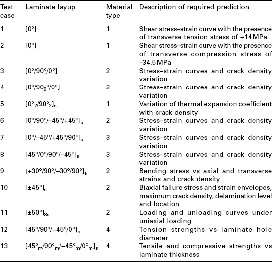
Thirteen different cases were selected covering eight different layups consisting of 0 °, [0 °/90 °/0 °], [0 °/90 °8/0 °], [0 °/90 °]s, family of [0 °/45 °/90 °/−45 °]s, [±45 °]s, [±50 °]s, and [30 °/90 °/−30 °/90 °]s laminates. Four different materials were used: AS4/3501-6 material, E-glass/epoxy material, G4-800/526 carbon/epoxy materials and IM7/8552 carbon/epoxy material. In addition, five different types of loadings were used: biaxial direct stresses, uniaxial monotonic tension, loading and unloading, bending, and cracking under thermal loading. Full details are provided in the paper by Kaddour et al. (2012) and are summarised in Table 1.6.
Methodologies used
Experts from academia, industry and software houses were invited to take part. These were all individuals or distinguished groups judged by the organisers (and other peers) to have contributed to the field and whose published papers appear to have distinct features capable of handling explicitly some of the issues highlighted in the previous section. A total of 12 different approaches are being employed by their originators. The models employed are representative of a number of different approaches including shear lag analysis, energy methods, micromechanics-based models, cohesive zone models, enhanced damage meso-models and continuum damage models and others.
1.1 Conclusions
1. Clear progress has been made in understanding the current boundaries of failure criteria for fibre reinforced polymer composites.
2. The first World-Wide Failure Exercise has established certain areas where the failure criteria were mature. It also identified areas where current models were immature.
3. The second exercise (WWFE-2) is currently underway to assess the capability of 3D failure criteria for applications including triaxial and through-thickness loadings. The results of this activity will be published soon.
4. The third exercise (WWFE-3) is also currently underway to assess the current modelling methodologies for advanced understanding of damage, crack initiation and propagation, loading and unloading, delamination, size effects, layup effects, stress concentration in practical multi-directional laminates. The findings are planned to be published soon.
1.2 Acknowledgements
The authors would like to thank all the participants in the World-Wide Failure Exercises for their excellent contributions and the significant efforts they have put in. Thanks also to the Royal Society in the United Kingdom for granting Dr Kaddour the Royal Society Industry Fellowship award.
1.10 References
Bogetti, T.A., Hoppel, C.P.R., Harik, V.M., Newill, J.F., Burns, B.P. Predicting the nonlinear response and progressive failure of composite laminates. Compos Sci Technol. 2004; 64:329–342.
Bogetti, T.A., Hoppel, C.P.R., Harik, V.M., Newill, J.F., Burns, B.P. Predicting the nonlinear response and failure of composite laminates: correlation with experimental results. Compos Sci Technol. 2004; 64:477–485.
Bogetti, T.A., Staniszewski, J., Burns, B.P., Hoppel, C.P.R., Gillespie, J.W., Jr., Tierney, J. Predicting the nonlinear response and progressive failure of composite laminates under tri-axial loading, 2012. [to be published].
Butalia, T.S., Wolfe, W.E. Strain energy based non-linear failure criterion: comparison of numerical predictions and experimental observations for symmetric composite laminates. Compos Sci Technol. 2002; 62:1695–1710.
Carrere, N., Laurin, F., Maire, J.-F. Micromechanical based hybrid mesoscopic 3D approach for non-linear progressive failure analysis of composite structures, 2012. [to be published].
Cuntze, R.G. The predictive capability of failure mode concept-based strength criteria for multidirectional laminates: Part B. Compos Sci Technol. 2004; 64:487–516.
Cuntze, R.G. The predictive capability of failure mode concept-based strength conditions for laminates composed of UD laminae under static tri-axial stress states, 2012. [to be published].
Cuntze, R.G., Freund, A. The predictive capability of Failure Mode Concept-based strength criteria for multidirectional laminates. Compos Sci Technol. 2004; 64:343–377.
Deuschle, H.M., Kröplin, B.-H. FE implementation of Puck’s failure theory for fibre reinforced composites under 3D-stress, 2012. [to be published].
Eckold, G.C. Failure criteria for use in the design environment. Compos Sci Technol. 1998; 58:1095–1106.
Eckold, G.C. Failure criteria for use in the design environment – Part B. Compos Sci Technol. 2002; 62:1561–1570.
Edge, E.C. Stress based Grant-Sanders method for predicting failure of composite laminates. Compos Sci Technol. 1998; 58:1043–1044.
Edge, E.C. Theory v. experiment comparison for stress based Grant-Sanders method. Compos Sci Technol. 2002; 62:1571–1590.
Gotsis, P.K., Chamis, C.C., Minnetyan, L. Prediction of composite laminate fracture: micromechanics and progressive fracture. Compos Sci Technol. 1998; 58:1137–1150.
Gotsis, P.K., Chamis, C.C., Minnetyan, L. Application of progressive fracture analysis for predicting failure envelopes and stress-strain behaviors of composite laminates: a comparison with experimental results. Compos Sci Technol. 2002; 62:1545–1560.
Hart-Smith, L.J. Predictions of the original and truncated maximum strain failure models for certain fibrous composite laminates. Compos Sci Technol. 1998; 58:1151–1178.
Hart-Smith, L.J. Predictions of a generalised maximum-shear-stress failure criterion for certain fibrous composite laminates. Compos Sci Technol. 1998; 58:1179–1208.
Hart-Smith, L.J. Expanding the capabilities of the T en-Percent Rule for predicting the strength of fibre-polymer composites. Compos Sci Technol. 2002; 62:1515–1544.
Hart-Smith, L.J. Comparison between theories and test data concerning the strength of various fibre-polymer composites. Compos Sci Technol. 2002; 62:1591–1618.
Hinton, M.J., Kaddour, A.S., Soden, P.D.Failure Criteria in Fibre Reinforced Polymer Composites: The World-Wide Failure Exercise. Oxford: Elsevier Science, 2004.
Huang, Y.C., Jin, K.K., Ha, S.K., Tsai, S.W. Prediction of 3D composite laminate response using micromechanics of failure, 2012. [to be published].
Huang, Z.-M. Correlation of the bridging model predictions of the biaxial failure strengths of fibrous laminates with experiments. Compos Sci Technol. 2004; 64:529–548.
Huang, Z.-M. A bridging model prediction of the tensile strength of composite laminates subjected to biaxial loads. Compos Sci Technol. 2004; 64:395–448.
Kaddour, A.S., Hinton, M.J. Input data for Test Cases used in benchmark triaxial failure theories of composites, 2012. [to be published].
Kaddour, A.S., Hinton, M.J., Li, S., Smith, P.A. Benchmarking of matrix cracking, damage and fracture machanics methodologies for fibre reinforced polymer composites: The third World-Wide Failure Exercise, 2012. [to be published].
Kress, G. Examination of Hashin’s failure criteria for the second World-Wide Failure Exercise, 2012. [to be published].
Kuraishi, A., Tsai, S.W., Liu, K. A progressive quadratic failure criterion, Part B. Compos Sci Technol. 2002; 62:1682–1696.
Liu, K.-S., Tsai, S.W. A progressive quadratic failure criterion of a laminate. Compos Sci Technol. 1998; 58:1023–1032.
Mayes, S.J., Hansen, A.C. Composite laminate failure analysis using multicontinuum theory. Compos Sci Technol. 2004; 64:379–394.
Mayes, S.J., Hansen, A.C. A comparison of multicontinuum theory based failure simulation with experimental results. Compos Sci Technol. 2004; 64:517–527.
McCartney, L.N. Predicting transverse crack formation in cross-ply laminate. Compos Sci Technol. 1998; 58:1069–1082.
McCartney, L.N. Predicting ply crack formation and failure in laminates. Compos Sci Technol. 2002; 62:1619–1632.
Nelson, E.E., Hansen, A.C., Mayes, S. Failure analysis of composite laminates subjected to hydrostatic stresses: a multicontinuum approach, 2012. [to be published].
Pinho, S.T., Darvizeh, R., Robinson, P., Schuecker, C., Camanho, P.P. Material and structural response of polymer-matrix fibre-reinforced composites, 2012. [to be published].
Puck, A., Schürmann, H. Failure analysis of FRP laminates by means of physically based phenomenological models. Compos Sci Technol. 1998; 58:1045–1068.
Puck, A., Schürmann, H. Failure analysis of FRP laminates by means of physically based phenomenological models – Part B. Compos Sci Technol. 2002; 62:11633–11672.
Rotem, A. Prediction of laminate failure with Rotem failure criterion. Compos Sci Technol. 1998; 58:1083–1094.
Rotem, A. The Rotem failure criterion theory and practice. Compos Sci Technol. 2002; 62:1663–1672.
Rotem, A. The Rotem failure criterion for fibrous laminated composite materials: three dimensional loading case, 2012. [to be published].
Sun, C.T., Tao, J.X. Prediction of failure envelopes and stress strain behaviours of composite laminates. Compos Sci Technol. 1998; 58:1125–1136.
Sun, C.T., Tao, J.X., Kaddour, A.S. Prediction of failure envelopes and stress-strain behaviour of composite laminates: comparison with experimental results. Compos Sci Technol. 2002; 62:1672–1682.
Wolfe, W.E., Butalia, T.S. A strain energy based failure criterion for nonlinear analysis of composite laminates subjected to biaxial loading. Compos Sci Technol. 1998; 58:1107–1124.
Ye, J., Zhang, D., Sheng, H. Prediction of failure envelopes and stress strain curves of composite laminates under triaxial loads, 2012. [to be published].
Zand, B., Butalia, T.S., Wolfe, W.E., Schoeppner, G.A. A strain energy based failure criterion for nonlinear analysis of composite laminates subjected to triaxial loading, 2012. [to be published].
Zhou, Y.-X., Huang, Z.-M. A bridging model prediction of the ultimate strength of composite laminates subjected to triaxial loads, 2012. [to be published].
Zinoviev, P., Grigoriev, S.V., Lebedeva, O.V., Tairova, L.R. Strength of multilayered composites under plane stress state. Compos Sci Technol. 1998; 58:1209–1224.
Zinoviev, P., Lebedeva, O.V., Tairova, L.R. Coupled analysis of experimental and theoretical results on the deformation and failure of laminated composites under a plane state of stress. Compos Sci Technol. 2002; 62:1171–1724.