Environmental induced failure in fibre-reinforced plastics
Abstract:
This chapter examines the failure behaviour of fibre-reinforced plastics when exposed to water and other degrading chemicals. It considers natural and artificial weathering through exposure to elevated humidity and temperature (hygrothermal ageing), seawater and salt spray, ultraviolet radiation, and biological organisms. Attention is given to industrial applications and service maintenance involving acids and alkalis, solvents and aircraft products (gasoline, jet fuel, grease and de-icing fluids), and synergisms between degrading agents including applied stress and pressure. The chapter includes modelling short- and long-term properties, and design, manufacturing of composite structures for use in chemical environments, and the use of coatings and sealants to prevent failure. It concludes with test methods and standards, future trends, and sources of further information and advice.
13.1 Introduction
In many industrial applications, the operating environments are highly aggressive leading to a reduction in structural integrity and service life. Prolonged, or even short-term, exposure to environmental agents (e.g. elevated temperature and hostile chemicals) can cause irreversible changes in the chemical and physical properties of fibre-reinforced plastics (FRPs). In some circumstances, only a few hours of exposure may lead to failure or seriously compromise material performance. Conversely, the rate of chemical degradation can be slow and insidious without evident signs of material deterioration. Irreversible property changes in composites can be induced by any number of degrading agents (or factors) acting alone or collectively. In many applications, composite structures will be exposed to a combination of two or more factors (e.g. temperature and humidity), often resulting in complex synergistic degradation of the material. Degradation caused by one agent can also reduce the resistance to other agents, similar to biological systems. Exposure to elevated temperatures or the application of applied stresses can accelerate the degradation effects of chemical agents. For example, the two predominant factors in climatic exposure are humidity and temperature. The severity of these two factors will depend on geographical location. The consequences of failures through environmental induced ageing can have significant ramifications both economically, and on health and safety to operators and local residents, as well as to the environment. The importance of understanding and predicting degradation behaviour is imperative to ensuring improved safety and the prevention of failures occurring during service. The strict health and safety regulatory environment for ensuring human and environment protection adds further pressure to develop improved inspection and operating regimes for the use of composites in safety critical applications.
Failure of FRPs, insofar as they become no longer fit for purpose, may occur because of cumulative damage to the thermosetting or thermoplastic matrix, fibre-matrix degradation, chemical attack of the fibres or a combination of two or more of these processes. In addition to inducing chemical reactions, absorbed chemicals induce important physical effects within the matrix (i.e. dimensional changes, resin plasticisation and leaching of matrix constituents). In the absence of environmental stress cracking (ESC), the amount and type of chemical absorbed by a polymer in a given time can be a useful guide as to the probable extent of physical changes or damage induced.
This chapter is concerned primarily with failure of FRPs caused through environmental degradation due to the effects of water, and other chemical agents, which may modify or degrade composite material properties, and consequently the performance of composite structures. Environmental factors, such as humidity, temperature, pressure, seawater, weathering and photo-oxidation, ionising radiation and biological degradation are covered along with the combined effects of stress, temperature and moisture (i.e. environmental stress corrosion cracking (ESCC)) on material performance. It covers chemicals, such as solvents (including paint strippers), acids and alkalis, and aircraft products (jet fuel, hydraulic oil and de-icing fluids). The chapter examines the influence of aggressive environmental media on the properties of different types of fibres; resin systems and the fibre–matrix interface, and discusses the impact on the failure mechanisms and long-term durability of FRPs. Thermal ageing, moisture and chemical resistance conditioning and testing, and artificial weathering are discussed. The chapter also examines analytical models for predicting the short-term properties and long-term behaviour of composite materials under various environmental regimes. It identifies factors to be considered when designing and manufacturing composite structures for use in chemical environments, including material selection, and the use of coatings and sealants to prevent failure. Test standards for assessing environmental degradation of polymeric materials are also included. The chapter concludes with future trends, sources of further information and advice, references and standards.
13.2 Chemical agents and degradation mechanisms
13.2.1 Introduction
Irreversible property changes leading to eventual failure can be induced by any number of environmental agents (see list below) acting alone or collectively.
• humidity (including hot/wet) exposures
• complete immersion in water at ambient and elevated temperatures
• freeze/thaw and dry/wet cyclic conditions
• thermal (heat ageing or sub-zero exposure)
• continuous or intermittent saltwater immersion or spray
• weathering (including rain and sand erosion)
• chemical (including acids, alkalis, solvents, aviation products and oxygen)
• ultraviolet and high-energy radiation
• electrical stress (e.g. lightning strike and galvanic reactions)
Although the list of environmental factors is too numerous to elaborate, the common denominator with all these factors is the possible detrimental effect on the composite properties, which is exacerbated in the presence of mechanical stress (static and fatigue). This section examines the degrading effects of various chemical environments on failure behaviour and considers the synergistic effects of chemical agents, temperature and mechanical stress on degradation. Weathering and photo-oxidation, high-energy radiation and biological (microbial) effects are also considered. A full list of recognised chemical agents and test methods for assessing the effects of chemical exposure are given in ISO (International Standards Organisation) 175.1 A list of ISO, ASTM (American Society for Testing and Materials), BSI (British Standards Institute) and CEN (Comité Européen de Normalisation) relating to chemical resistance testing is presented in Section 13.10.
13.2.2 Moisture degradation
Most FRPs will absorb small, but potentially damaging amounts of moisture from the surrounding environments with the degree of degradation that occurs being linked directly with the amount of moisture absorbed. The absorbed water may adversely affect the material in a number of ways:
• dimensional changes (swelling);
• appearance changes (colour, gloss, crazing, blistering, etc.);
• reduction in the glass transition temperature Tg of the resin; and
• reduction in mechanical and physical properties (i.e. stiffness, strength and hardness).
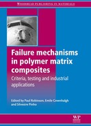
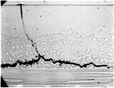
In many instances, water reacts with the matrix producing irreversible chemical changes and diminished performance. Capillary action along the fibres can account for a significant proportion of initial moisture uptake, although a chemically resistant matrix may encapsulate the fibres.2 Shrinkage of the resin away from the fibres during curing is a contributing factor to the capillary effect. Another contributing factor is poor adhesion between the fibre and the surrounding matrix due to either chemical incompatibility between the two constituents or degradation of the fibre sizing, as shown in Fig. 13.1. The effect of moisture is to cause hydrolytic breakdown of the fibre–matrix interface resulting in a loss in the efficiency of load transfer between the matrix and the fibre reinforcement. Poor interfacial bonding accelerates material degradation with consequent loss in stiffness and strength, and life expectancy of the composite.
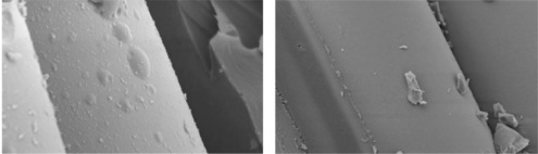
The moisture absorption kinetics differ widely between resin systems and also changes with chemical ageing. The Tg for a typical polyester resin decreases by approximately 15–20 °C for a 2% moisture weight gain. This reduction in Tg is induced by plasticisation (softening) of the polymer matrix and in some cases by loss of organic additives (e.g. plasticisers, pigments and fire retardants) through leaching to the surrounding media. The loss of plasticisers (toughening agents) can result in a reduction in Young’s modulus and elongation to break. The loss of stiffness and ductility can be attributed to structural changes of the resin system resulting from scission of the polymer chains through hydrolysis, leading to a decrease in cross-link density and molecular weight. Hydrolytic degradation is controlled by the diffusion of water in the material, which increases at elevated temperatures. Hydrolysis reactions are generally minimal under ambient conditions. It is advisable when using glass fibre-reinforced plastic (GRP) products to ensure that the maximum operating temperature is at least 30–40 °C below the Tg of the material (taking into account moisture effects). Figure 13.2 shows the effect of moisture content on Tg for a glass fibre-reinforced epoxy system that has been immersed in distilled/deionised water for prolonged periods of time at three different temperatures. It is worth noting that for some composite systems a loss in mechanical properties through moisture ingress is not always accompanied by a reduction in Tg. Reductions in flexural strength of the order of 20–40% have been observed for both thin woven glass and carbon laminates with polyester and vinyl ester resin systems immersed for 2 years in seawater at 30 °C.3 The long-term behaviour of isophthalic polyester composites is particularly poor. Leaching of constituents from the resin occurs at temperatures approaching 60 °C. The maximum operating temperature of glass fibre-reinforced polyester is close to room temperature.
Although the process of moisture absorption and desorption within the surface layers occurs almost immediately on contact with the environment, moisture diffusion into the bulk material is usually a slow process. It may take weeks to months before a substantial amount of moisture has been absorbed by the composite, and considerably longer periods (i.e. 1–2 years) before the material is saturated. The rate of moisture uptake by a composite laminate is dependent on the temperature, relative humidity, exposure time and mechanical load. At elevated temperatures, the rate of moisture uptake and material property degradation is accelerated.
The presence of tensile loads accelerates moisture uptake by opening existing internal cavities or voids, and by contributing to micro-crack formation. A laminate containing micro-cracks will absorb considerably more moisture than an undamaged laminate. Exposing the wet composite to sub-zero temperatures can further exacerbate this process.4 A commonly used test is to subject hot/wet conditioned laminates to thermal cycling in which the composite is exposed to temperatures as low as −55 °C for a given number of cycles to assess the laminate’s crack resistance.
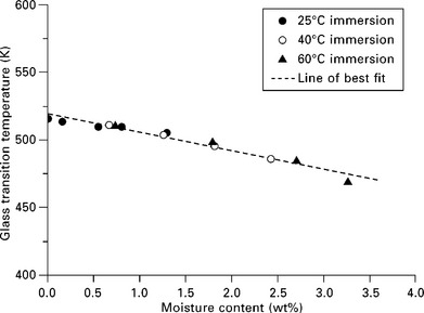
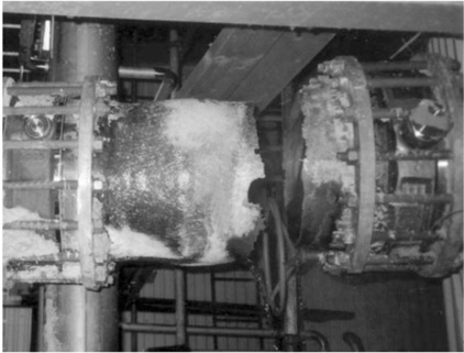
All laminates when exposed to marine environments will allow water vapour to permeate the structure. As the water diffuses into the composite, it reacts with any hydrolysable components (e.g. ester groups) inside the laminate to form tiny cells of concentrated solution. Under this osmotic process5,6 more water is drawn through the semi-permeable membrane of the laminate in an attempt to dilute the solution. The water can increase the fluid pressure of the cell by 50 atmospheres, which eventually distorts or bursts the laminate or gel-coat and can lead to blistering of the surface. Damage can be very extensive requiring major repair or the replacement of the structure (Fig. 13.3).
13.3 Osmotic blistering of a GRP boat hull with inset showing laminate breakdown. (courtesy of Minton, Treharne and Davies Ltd)
Osmosis blistering7,8 is a very common problem that occurs in GRPlaminated structures that have been immersed for long periods in water and is often observed in GRP boats, water tanks and swimming pools. A resin-rich layer (e.g. gel coat) is often applied (painted or sprayed) to the composite surface where the material is to be exposed for long periods to aqueous environments. This protective layer (~0.1–0.2 mm thick) acts as a barrier to moisture ingress, thereby protecting glass fibres from moisture degradation. Isophthalic-NPG (neo-pentyl glycol) resin systems are widely used for this purpose. Although the gel coat protects the underlying composite substrate by slowing water ingress, it is not an impermeable layer.9 The use of gel coats has been highly successful in protecting GRP marine structures with few failures due to wet ageing reported. Failures are more likely to result from poor maintenance or inadequate repair following a collision. Osmotic effects are amplified in the presence of hydrostatic pressure as experienced in sub-sea environments (e.g. submersibles). Simulations of sub-sea conditions10 have shown that increasing the hydrostatic pressure results in faster diffusion rates with epoxide and polyester-based resin systems showing larger increases in diffusivity compared with vinyl ester and PEEK (polyether ether ketone) resin systems. As with Tg, the moisture content is not a reliable indicator of mechanical property degradation.
Entrapped air/gas/moisture vapour under pressure expands as the structure is raised from depths (as external pressure decreases), analogous to the effect of the bends experienced by divers. As a result, cracking and delaminations may occur, thus compromising structural integrity. Porous materials can be expected to be far more prone to this effect than well-compacted materials. An increase in porosity results in an increase in both the rate of diffusion (diffusivity) and the level of absorbed moisture at saturation. Other issues to consider in sub-sea applications are the chemical composition and properties of seawater, pressure and depth effects, temperature, salinity, dissolved oxygen content, pH level, oceanic currents and biological attack.10
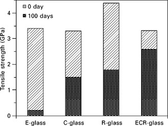
Moisture degradation is primarily an issue for glass fibres and aramid fibres. Carbon fibres tend to be stable in most environments. The tensile strength of freshly drawn E-glass fibres is typically 3.5 GPa. This strength can be fully realised, provided the fibres are carefully handled during fabrication to avoid surface damage and are stored in a dry environment. Exposure to humid air (including air-conditioned laboratories) will compromise the load-bearing capacity of the fibres, resulting in a loss of strength and an increase in strength variability.11 Carbon fibres are relatively insensitive to moisture, and hence the variability in the tensile breaking stress and strain for carbon fibre tows is noticeably less than for E-glass fibre tows.
The loss of tensile strength of E-glass fibres is dependent on exposure time, temperature and degree of humidity. On initial exposure to a humid/water environment, the rate of fibre degradation is fairly rapid, even in benign environments, such as air-conditioned laboratories. The tensile strength is reduced to 3.0 GPa after 3 weeks’ exposure to standard laboratory conditions (23 °C and 50% relative humidity (RH)). After 100 days, in air and water the strength is approximately 2.6 GPa and 2.1 GPa, respectively.12 Exposure to boiling water for 24 h results in a 75% loss of strength. As a consequence of handling and moisture, an intrinsic tensile strength of 2.0 GPa is often assumed for design purposes.
Degradation of E-glass fibres in water can be attributed mainly to leaching of alkali oxides (sodium and potassium oxide) from the fibre surface resulting in the formation of surface micro-cracks, which act as stress concentrators. The loss of strength can be expected to be permanent at all conditioning temperatures and exposure times. Deionised water is slightly more aggressive than either tap water or seawater. The presence of Na+ ions in solution slows down the exchange of alkali ions, such as NaOH−, and restricts entry of Cl− ions into the silic acid network.2 Chloride ions slow the degradation process, although only slightly. Under the influence of humidity or water, the fibre forms a water skin in which the alkali ions (e.g. NaOH−) are leached from the fibre surface and replaced by protons (H+ ion). The thickness of the silic acid structure or skin, which increases with exposure time, is dependent on the temperature and humidity of the surrounding environment. The water surrounding the glass fibres evolves into an aggressive alkali solution as the alkali ions dissolve out of the glass, slowly decomposing the glass fibres. Increasing the alkali content of the glass tends to reduce environmental attack from water and alkali solutions. Drying of the composite will remove most of the skin of water adjacent to the fibre, but a small permanent layer with retained water will still remain, and the mechanical properties of the fibre will be permanently degraded.
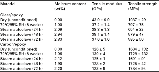
In contrast, the mechanical properties of carbon fibre systems when dried will tend to be similar to those observed for unconditioned material, provided the chemical composition of the matrix remains unaltered. Tables 13.1 and 13.2 compare the longitudinal tensile strength and modulus of unidirectional and cross-ply E-glass and carbon fibre-reinforced epoxy systems before and after exposure at 70 °C and 85% RH for 6 weeks.12 The observed increase in tensile strength of carbon/epoxy laminates can be partially attributed to residual stress relief and further curing of the resin system. For cross-ply laminates, a reduction in mechanical properties is accompanied by a reduction in crack density (i.e. cracks/mm).
The effect of moisture on aramid fibre-reinforced epoxy laminates is potentially greater than other composite systems. Aramid (e.g. Kevlar™ 49) fibres tend to absorb moisture and degrade at room temperature with the rate of degradation accelerating as temperature is increased. Substantial hygrothermal strength losses have been observed with these materials, particularly under natural weathering conditions (i.e. combination of moisture and ultraviolet light).
Freeze and freeze-thaw exposure are also of concern to engineers and designers of composite structures, particularly in the presence of moisture. Published information on the effect of freeze-thaw on FRPs is very limited; however, the effects of low-temperature thermal cycling are fairly well understood. At low temperatures, the presence of residual stresses resulting from a combination of resin shrinkage and differential thermal contraction between reinforcement and resin matrix can result in the formation of micro-cracks in the matrix and fibre–matrix interface. The degree of micro-damage, whose presence adversely affects laminate stiffness and strength properties, dimensional stability and fatigue resistance, is directly related to the extent of resin shrinkage during cure. Residual stresses increase as the temperature is decreased. Laminates containing significant amounts of moisture will experience severe stresses if the laminate becomes frozen due to the expansion of water when it freezes. This expansion can generate significant pressures in a laminate contributing to the initiation and growth of micro-cracks and delaminations. The resultant damage is associated with free moisture (ice particles) present within voids (cavities) and cracks rather than matrix swelling induced through moisture absorption. The severity of damage and subsequent deterioration of laminate properties increases with thermal cycling. An increase in damage also lowers the composite’s resistance to moisture ingress.
13.2.3 Chemical degradation
Most of the commonly used resin systems employed by the composite industry are far more chemical resistant to strong acids, salt solutions and oxidative agents (e.g. hydrogen peroxide and bleaches) than stainless steel or aluminium alloys. The polymer matrix acts as a chemical barrier to the corrosive effects of water/moisture, but also alkalis and mineral acids. However, failures are known to occur with, in some cases, serious consequences to human health and safety and the environment. As with moisture effects, acid and alkali degradation processes are accelerated at elevated temperatures. Compared with other glass fibre types (e.g. C, R and ECR™), E-glass is particularly vulnerable to attack from mineral acids (e.g. HCl and H2SO4) and alkalis (e.g. NaOH and KOH). Dilute mineral acids are encountered not only in the chemical plant industry, but are also present in industrial and household effluent and sewage. As acids come into contact with E-glass fibres, ionic exchange occurs between the metallic cations (e.g. Na+ ions) at the glass surface and the hydrogen ions in the acid solution, resulting in leaching of sodium, potassium, calcium, magnesium, boron and aluminium from the outer layer or sheath of the fibre.
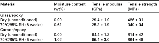
The dissolution of the supporting network results in a slight enlargement of the fibre diameter and shortening of the fibre length as longitudinal stresses relax, which is resisted by the unaffected core. As the outer layer becomes depleted, tensile stresses imposed by the core of the fibre build up, which significantly decreases the load capability of the fibre and eventually leads to cracks (helical in shape) as shown in Fig. 13.4.13 The helical nature of these cracks is due to the combination of unrestrained tangential and radial contractions. Axial cracks may also appear in the outer layer, which may spool off the fibre, like an onion peel, causing the unaffected core to be exposed. The leached outer layer is visible as a shell, which increases with time of acid exposure and eventually the glass fibres are completely leached over their entire diameter. The exposed fibres gradually lose weight, stiffness and strength.
13.4 Helical cracks in E-glass fibres exposed to H2SO4. (courtesy of J. Sillwood, National Physical Laboratory, UK)
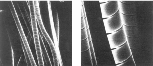
In the case of alkali attack, the chemical reaction involves a breakdown of the silica network by hydroxide (OH−) ions and eventually dissolution of all the species in the E-glass. The glass fibres gradually lose weight and strength when they are in contact with strong alkalis. Immersion in weak caustic solutions at room temperature can result in strength reductions of 30% within 2 weeks. Prolonged exposure of GRP structures to alkaline solutions can have serious consequences for structural integrity, leading to ultimate failure (see Fig. 13.5.)14,15 The rate of degradation of glass fibres to alkalis is not determined by the rate of diffusion, but by the active dissolution of the SiO2 network. The loss of mass is proportional to time. ECR-glass® (acid corrosion resistant) glass is only slightly more resistant to strong alkalis.
13.5 Failure of a GRP structure due to alkaline aqueous solution (unbleached pulp) at elevated temperature14 (courtesy of G. Bergman).
The resistance of glass fibres to alkalis and mineral acids can be improved by modifying the chemical composition (e.g. using ECR-glass® fibres for mineral acids, albeit at a high cost) or by chemical sizing (couplants, such as organosilanes) the fibre during fabrication so that there is a barrier coating, although this has limitations for some chemicals. S-2 glass®, C-glass and A-glass fibres are known to have superior resistance to mineral acids (e.g. H2SO4) than E-glass and ECR-glass® fibres with a substantial reduction of fibre dissolution when immersed in solution.2,16 Exposure to 0.5 M or (1N) solution of H2SO4 results in severe corrosion of E-glass fibres. (Note: A one normal (1 N) solution contains one gram-equivalent weight of a particular substance dissolved in 1 litre of solution.) Strength retention is essentially zero after 2 weeks’ immersion in the acidic solution at room temperature15 (see Fig. 13.6).
A number of other chemical agents relating to in-service environmental conditions, handling and maintenance (or even accidental contact) are known to have detrimental effects on the durability of composite laminates. Exposure to solvents such as paint strippers (e.g. methylene chloride) will soften and dissolve many resin systems. Paint strippers combined with abrasion techniques can cause irreversible material damage. Aircraft, boats and bridges may need to be repainted repeatedly every 2–3 years during service life, which can extend to 20–50 years (or more), which requires removal of the old paint before recoating. Paint strippers, such as methylene chloride, phenol, benzyl alcohol and benzene alcohol blends, will soften and dissolve the polymer matrix. In view of the solvent sensitivity of polymers, it is important to prevent solvents coming into contact with the composite during service life. Chemical paint strippers are banned from use with composite aircraft components.
Hydraulic fluid has a similar effect to that of methylene chloride, but takes longer. Contact with aircraft fuel, gasoline, oil, hydraulic, brake and transmission fluids, lubricants, coolants and de-icing and antifreeze compounds are also known to have adverse effects on composite performance through degradation of the polymer matrix.17,18 Whilst de-icing fluid ethylene glycol has been found to have minimal effect on the mechanical properties of structural adhesives, exposure to diethylene glycol monoethyl ether (DGME) can cause severe deterioration of these materials.19 As mentioned previously, synergistic effects are often observed between the various environmental factors resulting in amplification of the degradation process. The combination of JP-4 fuel and water is more aggressive than the two media acting alone. The effect of these highly destructive processes is often evidenced by a degraded surface appearance (i.e. discolouration, cracks and pitting, loss of surface reflectivity, increased surface roughness and exposure of underlying fibres).
Chemical attack of thermoplastics involves specific chemical reaction of the polymer with the fluid with the most common mode of failure being hydrolysis by water, acids and alkalis. Esters, amides, imides, and carbonate groups are particularly susceptible. Where these groups are located in the backbone chain rather than the side chain, chain scission ensues. The reduction in molecular weight consequent upon chain scission can lead to a reduction of toughness and fracture strain. The higher the concentration of absorbed fluid, the greater the level of degradation with the process accelerated at elevated temperatures and in the presence of applied stress. Stress and elevated temperatures are known to accelerate the chain scission process and also the rate of fluid uptake. Metallic and GRP vessels and pipes are frequently fitted with a thermoplastic lining (e.g. nylon, polypropylene, polyethylene and poly vinylidine fluoride), which acts as a corrosion or permeation barrier to chemical environments.
The majority of thermosetting plastics (e.g. polyester, vinylester and epoxide resins) are susceptible to oxidation by numerous oxidising agents, from exposure to elevated temperatures (i.e. thermo-oxidation), hydrogen peroxide and bleaches (e.g. hypochlorite). It is often other constituents, such as fillers, catalysts, hardeners, pigments or fire retardants, rather than the resin or fibre reinforcement that are more reactive to these chemicals. Although usually aware of the potential durability problems associated with these additives, formulators and users often overlook minor constituents such as catalysts, hardeners, pigments and processing aids.
Exposure to salt spray or salt water will degrade GRP systems with the degree of protection depending on the permeability of the resin to diffusion of chloride ions and the ability of the matrix and interface to resist premature cracking, which would allow the environment to come in direct contact with the fibres resulting in corrosion of the reinforcement. Molecular chlorine present in aqueous solutions will cause a gradual reduction in laminate thickness and mechanical properties. The active form of chlorine in an aqueous solution depends on the pH of the solution. Figure 13.7 illustrates damage induced in GRP pipes when exposed to molecular chlorine and hydrogen chloride.
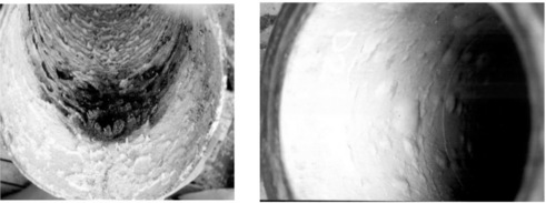
13.7 Chlorine degradation (left) and HCl induced blistering (right) of a GRP pipe. (courtesy of ESR Technology Ltd, UK)
Most FRP constituents are non-conductive and, as a consequence, electrochemical corrosion is not an issue. However, electrochemical (galvanic) corrosion can pose a problem for hybrid structures consisting of coupled CFRP and metallic (e.g. aluminium alloys and steel) components. Insulating the carbon fibres with glass cloth can prevent galvanic corrosion. Galvanic reaction occurs when two different conductive materials with different galvanic potential are in contact in the presence of water (electrolyte). The more anodic material will corrode at an accelerated rate resulting in a build-up of corrosion product near the contact area. The galvanic effect is dependent on moisture content, temperature and electrical and chemical properties of the galvanic cell electrodes and electrolyte. Carbon fibre surfaces are electrochemically active supporting chemical reactions. The main reaction is cathodic reduction of dissolved oxygen to form hydroxyl ions. The reaction rate is initially controlled by the diffusion rate of the reactive components through the polymer matrix to the carbon fibre surface with the rate controlled by the type, thickness and quality of the polymer layer and the solution chemistry. Another factor is the retained moisture in the polymer after manufacture. Once the galvanic cell is complete then the cathodic and anodic reactions initiate. The hydroxyl ions build up on the carbon fibres and react with components in the solution, such as sodium ions to balance the electrical charge. This sets up an osmotic condition as the pressure from the NaOH increases, which can lead to blistering. The reaction of the composite to the osmotic pressure determines the degree of damage done to the laminate and protective polymeric layer.
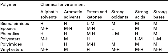
As with most materials, different resin systems have specific attributes that provide protection against a range of chemicals. The problem for designers and engineers is selecting a resin system that will guarantee the required design life performance when exposed to the chemicals and solvents that the composite is expected to experience during service life. This includes secondary environments, such as maintenance activities involving chemical cleaners and paint strippers. There is no single polymer that offers a universal solution, protection from all environments. Being impervious to one environment is no guarantee of resistance to other environments. A resin system with maximum resistance to acids generally has poor resistance to bases and vice versa. Polymers with dense cross-linked molecular structures generally have good resistance to chemicals and organic solvents, and high temperatures. Most thermosetting polymers tend to be hydrolytically stable in the presence of most organic solvents, and moderate acids and bases. Although at elevated temperatures (> 70 °C), these polymers are susceptible to hydrolysis, showing considerable loss in mechanical performance, thermoplastics can be appreciably degraded when exposed to a range of organic solvents, acids or bases. The chemical resistance of various types of thermoset resins are summarised in Table 13.3; exceptions do exist and a proper assessment would be required on a case-by-case basis.
13.2.4 Environmental stress corrosion cracking (ESCC)
The process of fibre degradation is accelerated under mechanical loads with the long-term strength of GRP laminates under hostile environments being controlled by stress corrosion of the fibre reinforcement.2,20–22 Delayed brittle failure through environmental stress corrosion cracking (ESCC) is known to occur in GRP structures, such as filament wound pipes transporting oil and gas, and chemical storage vessels,23–25 as a result of the combined effect of hostile chemicals and applied stress. Hostile chemical environments include water and acidic solutions (see Fig. 13.8). The timescales involved inducing ESCC failure increase as the initial applied stress is reduced.
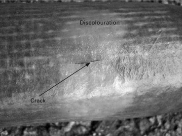
13.8 HCI induced stress corrosion cracking and discolouration of GRP pipe. (courtesy of K. Borchers, Dow Deutschland Anlagengesellschaft mbH, Stade, Germany)
ESCC of glass fibres can be activated by either moisture ingress (weepage) through pre-existing matrix micro-cracks or moisture diffusion through the matrix. The process can be initiated simply by exposure of the composite to humid environments.26 ESCC of glass fibres is associated with the rupture of Si–O–Si siloxane bonds that form the silicate network and ion exchange reaction between the metallic cations (e.g. Na+) at the fibre surface and the H+ ions (protons) in the surrounding environment. The applied stress contributes to the process through extension of the Si–O bonds, which accelerates the breakage reaction rate of the chemical bonds.2,22 This chemical reaction leads to an increase in the alkaline concentration (pH level) at the tip of a crack or flaw contributing further to the dissolution to alkali ions from the glass fibre; slowly decomposing the glass fibres and causing spiral cracking of the outer sheath of the fibres as previously shown in Fig. 13.4. ESCC is not limited to static loads; it applies equally to dynamic loading conditions.22,23
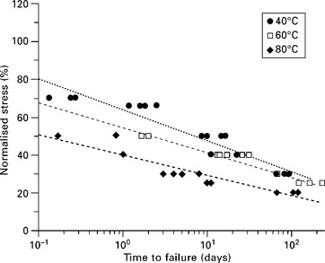
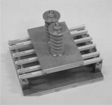
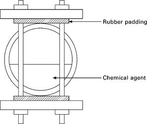
Static fatigue or creep rupture, which refers to time-dependent failure of the material when subjected to constant load, is used as a measure for gauging the relative resistance of the material (i.e. fibre or composite) to chemical environments. Figure 13.9 shows an optical micrograph of a failed GRP pipe resulting from static fatigue.23 The less resistant a fibre is to a particular environment, the more rapid the drop in the rupture stress time curve. For a given applied load, the stress rupture time decreases with increasing humidity and temperature, or chemical concentration. Figure 13.10 compares the static fatigue curves of glass fibre-reinforced vinylester pultruded rods subjected to four-point bending whilst immersed in porewater (alkaline) solution (pH 12.6–13.0) at 40 °C, 60 °C and 80 °C (see American Concrete Institute standard ACI 440.3R-0427). The self-stressing fixture used in the tests is shown in Fig. 13.11. The rate of moisture diffusion increases with increasing applied stress and temperature; however, the fatigue life was mainly influenced by the applied stress and temperature rather than moisture content. The degradation process is enhanced by capillary diffusion along the fibre–matrix interface.22
13.9 Optical micrograph of a failed GRP pipe resulting from static fatigue23. (courtesy of ESR Technology Ltd, UK)
Environmental stress cracking (ESC) remains one of the most common causes of failure in polymers. The main reason for this is the complexity of the phenomenon, with aspects such as chemical compatibility, liquid diffusion, and craze formation and crack development all contributing. While crystalline (thermoplastic) and amorphous (thermosetting) polymers are both susceptible to ESC, thermosetting polymers are particularly susceptible due to the relatively open structure of amorphous polymers that leads to easy fluid penetration. Once the fluid has penetrated the polymer it becomes locally dissolved promoting cracking and crazing in the polymer. Cracking is normally preceded by the formation of crazes initiated at sites of stress concentration or in regions of local microstructure heterogeneity. Exposure to moderate levels of applied stress for extended periods of time can induce crazing and cracking in polymers, and is the underlying cause of long-term transition from brittle behaviour for ductile polymers. This mechanism, known as creep (or stress) rupture is a common cause of polymer failure, and consequently has significant ramifications for the chemical resistance of FRPs.28–30 It is worth noting that rapid damage formation can occur within the polymer matrix in circumstances where environment exposure times are short, but the time under stress prior to exposure has been long. Thermal stresses (strains) can also affect ESCC of FRPs.
13.2.5 Elevated temperature and thermo-oxidation
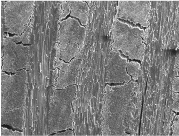
Prolonged, or even short-term, exposure to elevated temperatures will often produce irreversible chemical and physical changes within FRPs. Increased temperature accelerates most of the degradation processes that occur in composite materials, such as oxidation, chemical attack and mechanical creep. As the temperature increases, mechanical properties such as stiffness and strength tend to decrease. Oxidation is generally considered to be the most serious problem when using polymers at elevated temperatures, with the rate of thermo-oxidative degradation increasing with the amount of oxygen present.18,31 Elevated temperatures also depolymerise resins (chain scission) and degrade the fibre-matrix interface. Physical changes include polymer structure shrinkage, pore formation and weight loss through chemical decomposition of the polymer.32 At extremely high temperatures, as experienced in fires, fibre ablation occurs.33 A SEM image of heat degraded woven CFRP laminate following exposure to 1000 °C in argon is presented in Fig. 13.12. The overall degradation process will often involve a relatively long induction period during which little degradation is observed. At the end of this period, there is a rapid increase in degradation leading to a significant reduction in the mechanical properties of the composite. This induction period is temperature sensitive and is reduced significantly at elevated temperatures. The induction period of the degradation process can normally be regarded as the serviceable lifetime of the composite. A sudden brief exposure to high temperatures can result in a phenomenon known as thermal spiking, which can lead to excessive localised stresses with deleterious effects on structural performance. The effects of rapidly driven-off moisture through thermal spiking can also be expected to contribute to damage.
13.2.6 Weathering and photo-oxidation
Weathering or more specifically photo-oxidation of polymers refers to the chemical and physical changes that occur when ultraviolet (UV) radiation is absorbed by a polymer. The UV radiation spectrum comprises wavelengths of between 290 and 400 nm, which corresponds to energies of between 415 and 300 kJ/mol. These energies are in the same range as the bond energies of many organic compounds. Chemical reactions are induced when specific functional groups absorb the UV radiation. Free radicals liberated in the process will trigger further reactions. The deleterious effect will be dependent on the chemical nature of the material, environmental factors such as temperature and humidity, and exposure time. Material changes include discolouration (yellowing and bleaching), embrittlement, and loss of mechanical and physical properties. Photo-oxidative sensitivity may also increase with prolonged exposure to pollutants.18
UV radiation can be divided into three groups of wavelengths:
• UVA (315–400 nm) – least harmful to polymers, forming 6% of the total solar radiation reaching earth.
• UVB (280–315 nm) – more damaging to polymers, forming 0.1% of the total solar radiation reaching earth.
• UVC (<280 nm) – most harmful to polymers, but is filtered out by the Earth’s atmosphere.
UV radiation below 350 nm is absorbed by window glass, thus eliminating UVB radiation indoors.
When a polymer is exposed to solar radiation, the energy absorbed by the polymer results in the formation of free radicals within the polymer by the dissociation of the C–H bonds. The extent of this chemical reaction depends on the radiation exposure, that is the quantity of ultraviolet light (<350 nm) to which it is exposed. Once free radicals have been produced, reaction with oxygen generates hydroperoxides,34 which can dissociate further to produce a series of decomposition products including aldehydes and ketones. The presence of these carbonyl groups in a degraded polymer can be used as a chemical index for degradation. Once formed, these free radicals can continue to react via propagation reactions long after the initial UV exposure has ended. The formation and propagation of free radicals in itself does not seriously affect the mechanical properties of the polymer, as free radicals do not significantly alter the long-chain nature of the polymer molecules. Degradation of the mechanical properties occurs because the free radicals produced are highly unstable and readily undergo chain scission reactions. This results in the formation of two smaller polymer chains, one of which is a free radical and capable of further reactions.34
The intensity of the UV radiation decreases with increasing depth in the material, so that the reaction tends to be a near surface process. Shorter wavelengths have a far more deleterious effect on material properties than longer wavelengths. Longer wavelengths will penetrate deeper into the material, but are not easily absorbed, whereas the total energy of shorter wavelengths tends to be absorbed within a few micrometers of the surface. Since oxygen is involved in the reaction process, there is an important balance between UV radiation and oxygen diffusion, and of course temperature since that will also determine the kinetics of reaction and the transport of reactive species. Under natural exposure conditions there will be wetting and drying cycles and dark periods. The significance of the latter is that some recovery of the oxygen concentration in the material can occur, which otherwise is confined to the very near surface due to consumption by reaction with the polymer radicals. Since the concentration of these radicals diminishes by termination reaction during the dark period, oxygen ingress can extend to greater depth.
Geographical location, seasonal variations and time of day play a significant role in the length, intensity and wavelengths experienced. Equatorial latitudes are particularly hostile in terms of UV exposure, where due to the high solar angle the levels of UV radiation and temperature are higher and the range of wavelengths transmitted by the Earth’s atmosphere extends even lower (i.e. shorter wavelengths). At higher altitudes, a thinner atmosphere absorbs less UV radiation. The presence of water increases UV degradation, because the dissolved oxygen in water is more active in promoting photo-oxidation than oxygen in the air.
The effects of natural weathering on structural FRPs tends to be confined to the surface (mainly cosmetic) and seldom poses a serious threat to structural integrity. The use of a protective coating (paint or gel coat) is often employed to combat the effects of weathering. UV resistance of the resin can also be improved by including additives, such as antioxidants, thermal and UV stabilisers, and pigments. Antioxidants slow down the process of oxidative degradation, prolonging the life of the product. Thermal stabilisers are added to protect the adhesive system from chemical breakdown caused by heat and UV radiation, whilst UV stabilisers protect against UV degradation and exposure to fluorescent light and filtered daylight. Pigments alter the absorption characteristics of the material acting as a screen against UV radiation when compounded with the adhesive. Examples of commonly used pigments are carbon black, titanium dioxide, zinc oxide and barium sulphate. The costs of additives can often be prohibitive and also may adversely alter mechanical performance. Carbon black is particularly effective in protecting against UV radiation and is inexpensive. It absorbs UV radiation and protects the polymer chains.
13.2.7 High-energy radiation
High-energy radiation covers a wide range of different forms of high-energy particulate and electromagnetic radiation including X-rays, gamma rays, neutrons, alpha particles and beta particles. When a FRP is irradiated, the ionising radiation induces degradation by the formation of free radicals or ions in the polymer matrix. These reactive intermediates are capable of initiating chemical reactions which occur by free radical or ionic mechanisms and which result in scission as well as in cross-linking reactions. Free radicals with a long lifetime can be present in the bulk of the material after irradiation and still cause changes in properties even a long time after exposure. The intensity of ionising radiation on the Earth’s surface is not normally high enough to significantly affect most polymers, as these materials tend to be highly cross-linked and exhibit high temperature resistance. Radiation resistance of epoxy resins is improved by using aromatic curing agents. Radiation exposure tests are required for products for use in the nuclear industry and applications where radiation is used (e.g. medical X-rays and sterilisation). ASTM D187935 specifies methods for evaluating resistance to radiation.
13.2.8 Biological degradation
Biological degradation is not a common form of degradation as most polymers are resistant to microbiological attack by fungi or bacteria. It is the chemical additives and pigments that are usually susceptible to microbial attack, which tends to occur on exposed surfaces due to oxidation of the additives. Polymers that have good water and weather resistance generally have greater resistance to microbial attack. Geographical location and seasonal effects are important because micro-organism growth is more rapid in warm, humid climates than cold, dry climates. Microbial testing generally consists of exposing materials to an outdoor environment in geographical locations where weather conditions are favourable to microbial growth (see ASTM G2136 and ISO 84637). The angle of exposure to sunlight and weather conditions will influence the extent and duration of microbial attack. An alternative approach (known as soil burial) is to bury specimens for set periods of time and then to exhume and examine the specimens for the effects of microbial attack.
There is little evidence to suggest adverse structural changes occur in composites through biological (marine organisms and bacteria) attack.7,10 Hard (animals with calcium carbonate shells) and soft (algae and animals with soft structures) marine organisms growing on the surfaces of GRP marine vessels have minimal effect on the material properties of the composite, although these animals may play a role in damage development by increasing load on the structure, altering the composite surface and reducing exchanges (moisture diffusion and leaching) between the composite and the surrounding medium. Removal of marine organisms from the surface of marine vessels is probably more hazardous to the composite than the biological action of the marine organisms.
Resistance to mould, fungi and bacteria can be improved by including antimicrobial additives (also known as fungicides or biocides), uniformly distributed throughout the polymer during the compounding process or alternatively by applying a suitable protective coating (gel coat and anti-fouling treatments in the case of marine vessels). Antimicrobials can provide protection against mould, mildew, fungi and bacterial growth, which can cause discolouration, embrittlement and sometimes failure.
13.3 Environmental conditioning and testing
13.3.1 Introduction
A number of techniques have been employed to accelerate testing of FRPs. The usual approach for environmental testing has been to increase the temperature, humidity level or pressure (and in the case of chemical exposure the concentration level of the chemical agent). However, there is a temperature limit to which most polymer resins can be raised without affecting a change in the degradation mechanism (e.g. moisture absorption). Above this critical temperature, there is a strong possibility of altering the degradation mechanism. It is important that the ageing conditions selected recreate the same failure mechanisms that would be experienced in service. An alternative approach to increasing the level of the degradation agent is to increase the frequency of application of the degradation agent. An example is chemical resistance where exposure may be continuous, whereas in-service exposure is intermittent. The concern is that continuous exposure may result in a different response to actual service conditions. The use of relatively small samples for longer times under less severe conditions could potentially be used, provided the data generated can be scaled up to predict the long-term performance of more realistic size structures.
Key to the success of accelerated testing is the ability to correlate laboratory test data with service performance. Although accelerated ageing is widely used, it is seldom possible to establish a one-to-one correlation between the rate of degradation in the accelerated test and actual service conditions. A full understanding of environmental degradation effects is not yet available and there is no consensus as to a satisfactory accelerated ageing approach. The reader is referred to NPL Measurement Good Practice Guides 102 and 10338,39 for more detailed coverage. A list of ASTM, BSI and ISO standards for environmental testing is included in Section 13.10.
13.3.2 Thermal ageing
Thermal ageing studies generally involve conditioning samples at either subambient or elevated temperatures in a temperature-controlled chamber, and then measuring residual properties after a few weeks or months. Thermal ageing tests18 should include a minimum of three (preferably five) temperatures for periods of 1000 h (~6 weeks) or more in order to generate sufficient data that can be extrapolated to lower temperatures (i.e. service conditions). An Arrhenius law is often applied to the test data in order to predict behaviour at lower temperatures. However, this is reliant upon the degradation mechanism at the highest temperature being the same as experienced at the lower temperatures. Care needs to be taken when testing moisture pre-conditioned samples to prevent drying of the sample during the test.
Heat distortion temperature (HDT) is often the only criterion used in determining a material’s ‘fitness for purpose’ at elevated temperatures (i.e. upper of safe operating temperature at which the material can support a load for any appreciable time). The test procedure for determining HDT, as described in ISO 75,1 consists of three-point loading of a rectangular beam immersed in a heated mineral oil bath, whose temperature is constantly increased at a rate of 2 °C/min. The central deflection is continuously monitored. HDT is reached when the central deflection of the test specimen reaches a specified deflection value for a given nominal surface stress. HDT test data are only suitable for materials selection and acceptance, and not for design purposes. The results obtained using this method do not necessarily represent maximum use temperatures, because in practice essential factors such as time, loading conditions and nominal surface stress may differ for the different testing conditions. Tg can also be used to set upper service temperature limits for FRPs.
Thermo-oxidative ageing is carried out under vacuum or controlled barometric conditions. Thermal gravimetric analysis (TGA) can be used to monitor weight changes in a sample as a function of temperature. The technique is primarily used for studying degradation processes, providing information on thermal oxidative degradation rates and thermal degradation temperatures of polymeric materials. TGA results are not a reliable predictor of long-term performance or a good indicator for estimating long-term performance at a given temperature, as small weight losses may correspond to large decreases in mechanical properties.31,40 Small errors in weight measurement can result in large errors in the estimates of mechanical properties. ASTM D410241 specifies a test method for the determination of the weight loss of carbon fibres exposed to ambient hot air, as a means of characterising thermo-oxidative resistance.
13.3.3 Moisture conditioning and testing
Moisture conditioning can be carried out using either full immersion (where solution chemistry needs to be considered) or in a humid atmosphere (where RH should be controlled). Absorption and diffusion rates are also temperature dependent. Equilibrium moisture concentrations normally increase with increasing RH. Immersion usually results in a higher equilibrium moisture concentration than atmospheric exposure. The approach often adopted is to define a constant exposure environment that will produce a moisture level that is representative of a component or structure that has been exposed to a real-life environment at a particular geographical location. The variability of a natural environment, that is daily, monthly or seasonal changes in temperature and humidity, are known to be a major factor in determining both the final moisture equilibrium level in the material and the distribution of moisture in the outer surface layers. The military considers the worst worldwide environment to be represented by 70 °C and 85% RH.
The natural process of moisture absorption is normally very slow, particularly for thick sections, and this makes it very difficult to reach an adequate degree of degradation in a structural test element in practical timescales. It has been found necessary, therefore, to speed up the moisture diffusion process by employing an accelerated conditioning technique that can ensure a representative level of degradation in a significantly reduced time. There are two basic methods of moisture conditioning:
• fixed-time conditioning, where a test specimen is exposed to a conditioning environment for a specified period of time; and
• equilibrium conditioning, where a specimen is exposed until the material reaches equilibrium with the conditioning environment.
The first technique is routinely employed for assessing the durability of composites. This approach results in non-uniform moisture distribution through the thickness of the test specimen. Test data obtained from specimens conditioned in this manner are considered suitable only for comparing different batches of the same material or for quality control tests.
Ideally, comparative studies of water absorption properties of materials should be carried out using only the equilibrium moisture content of materials exposed to identical conditions. Equilibrium moisture concentration is most likely to indicate ‘worst-case’ material properties. Comparisons between composites with different moisture absorption characteristics are possible if the materials are preconditioned to equilibrium. The thicker the material, the longer the time required to reach equilibrium, hence the use of relatively thin specimens to determine the ‘through-the-thickness’ moisture diffusion coefficient.
An alternative approach to reaching an equilibrium condition involves altering the acceptance criteria to a given percentage of the chosen equilibrium condition. Conditioning the material to 95% of the full equilibrium state takes a relatively shorter time to reach than the full (100%) equilibrium condition. The time required to obtain the last 5% can take longer than the time taken to reach the 95% level. Clearly a very large saving in time is possible if 95% of equilibrium can be justified in terms of a non-significant change in strength and stiffness properties. Although accelerated ageing is widely used, a full understanding of the effects is not yet available and there is no consensus as to a satisfactory accelerated test.
ISO 6242 describes a procedure for determining the moisture absorption properties and/or diffusion coefficients in the ‘through-the-thickness’ direction of flat and curved solid plastics. It is suitable for use with composites and resins. The method can be applied to vapour exposure and liquid immersion. Conditioning usually consists of exposing pre-dried specimens to a steady-state environment (i.e. constant temperature and constant moisture exposure level) and measuring the moisture gain (i.e. average moisture content) for a prescribed period of time or until the specimen reaches moisture equilibrium. The amount of water absorbed by the specimen is determined by measuring its change in mass (i.e. difference between initial mass and the mass after exposure). All surfaces are in contact with the test environment. It is recommended that specimens be pre-dried in an oven maintained at 50 ± 2 °C until the specimen weight reaches a constant value. The temperature of the drying oven should not exceed the maximum operating temperature of the composite. Travellers (specimens with identical material properties, geometry and processing history as the test specimen) are used to monitor specimen moisture content throughout the environmental history (i.e. manufacture, storage, pre-conditioning and testing). The recommended maximum conditioning temperatures (not to be exceeded) are 45 °C and 70 °C for 120 °C and 180 °C cure systems, respectively.
Exposure to superheated pressurised steam (e.g. 2.2 bar and 136 °C) can induce levels of moisture of 2–3 wt% in epoxy-based composites within 48 h. The results presented in Table 13.112 indicate that steam autoclave conditioning is a viable option for inducing accelerated ageing, particularly for those systems possessing a cure temperature and a Tg in excess of 120–140 °C. The technique can be expected to prove too destructive for materials possessing low Tg values, such as polyester and vinyl ester resins. This approach may be useful for conditioning thick laminated sections and for identifying a worst-case scenario as to material degradation.
The rate of moisture uptake of specimens immersed in a fluid under pressure, such as deep-sea environments, may be expected to increase with an increase in pressure. Poorly compacted materials (i.e. high porosity) tend to absorb moisture more rapidly under pressurised conditions than would occur under atmospheric conditions. Pressurised fluid tests simulating deep-sea conditions can be carried out in specially designed pressure autoclaves, which can be heated internally using heating elements or externally using a heating blanket. Depressurising samples back to atmospheric pressure can induce additional damage similar to the bends, particularly in porous materials. Cycling between high and low pressure can propagate damage in FRPs.
13.3.4 Chemical resistance testing
The general approach for accelerated chemical resistance testing of polymeric materials has been to increase the temperature, chemical concentration or pressure. ASTM C58143 is widely used within the chemical processing industry for determining chemical resistance of thermosetting resins used in GRP structures. A variety of properties including Barcol hardness, flexural modulus and strength, and Tg are measured at regular intervals for periods up to 1 year. Part 2 of BS EN 1312144 is devoted solely to the determination of chemical resistance as befits a standard on chemical process vessels and aims to provide a partial design factor, A2, that can be used in the design of a component to take into account the chemical resistance of the material from which it is constructed. Table 7.1 of the standard gives the required thickness for different protective layers, which may be a single protective layer (SPL), a chemically resistant layer (CRL) or one of several thermoplastic linings (TPL).
In accordance with the main philosophy, the design factor A2 is determined using one of several methods depending on circumstances. Five methods are given for determining the factor:39
It is permissible to use the lowest value, if more than one method is used. In more detail the methods are:
• The aggressive environments are divided into Categories 1, 2 and 3 media. There are comprehensive instructions depending on service temperatures, type of lining, etc.
• For materials with a HDT 20 °C greater than the service temperature, cured according to the manufacturer’s instructions, partial factors vary between 1.1 and 1.4, and 1.1 and 1.8, for post-cured and non-post-cured material, respectively, based on the manufacturer’s recommendations.
• Similar approach for thermoplastic liners when used.
• For service experience greater than 3 years, the same factor may be used, whereas if it has been inspected after this period and found to be satisfactory, a reduction not exceeding 0.1 can be made in the design factor. The same factor can be applied for service experience between 6 months and 3 years if internal inspection is satisfactory.
• Experimental testing is undertaken using the single-sided exposure arrangement where one test plate is in the vapour phase and one in the fluid phase. Assessment is based a standardised ~3 mm laminate of fixed weight content made by a prescribed method. The tests are undertaken at the design service temperature for a range of exposure times, such as 1, 4, 8 and 16 weeks. It is recommended that four exposure units be employed.
Degradation is assessed on a combination of appearance changes (10 assessment parameters, e.g. gloss), dimensional stability (3 parameters) and flexural strength/modulus using BS EN 13121-2.44 For each property, a scoring system is used including a weighting system that increases in order of the above text, with mechanical tests the most important to the final score (see Table 13.4). The flexural properties are plotted as a function of the exposure time and extrapolated to the 50% retention point (normally strength as modulus is relatively insensitive to conditioning). If this point is obtained before 10 years, then the material should be rejected for this application (e.g. temperature, concentration, etc.). Otherwise, the score varies from 0 to 10 based on the percentage loss after 10 years, from 0% to 50%, respectively. For example, if colour, gloss retention and Barcol hardness, are the measured criteria then the maximum (worst) score would be:
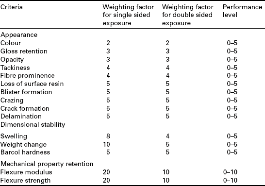
The material should be accepted for the application if the combined score of the tests results is ≤ 50% of the total score possible for the tests conducted. Depending on the total score for all aspects, as a percentage of the maximum that could be obtained for the parameters assessed, the partial factor A2 is obtained from a chart within the range 1.1 to 1.4 (see Table 13.5). The weighting factors are different for single-sided and full immersion. The test can also be conducted by full immersion of 100 × 125 mm plates of the laminate or by testing in situ within a tank.
Table 13.5
Determination of partial design factor, A2
| Total assessment score (%) | A2 |
| ≤ 20 | 1.1 |
| ≤ 30 | 1.2 |
| ≤ 40 | 1.3 |
| ≤ 50 | 1.4 |
| > 50 | Unsuitable for purpose |
British standard BS 499445 specifies requirements for the design, materials selection, construction, inspection, testing and erection of vessels and tanks in FRPs. The standard covers a wide range of materials and processing routes, and includes design factors to account for the deterioration of the laminated structure due to long-term exposure to combinations of chemical environments, elevated temperature and sub-zero temperatures, and alternating loads. Geometries covered include cylindrical and spherical shells, rectangular tanks, flanges and domes. The document claims that the adoption of a minimum design factor will prevent ESCC of the laminated vessels and tanks exposed to aqueous environments. The evaluation of ESC resistance of polymers is covered by a number of national and international standards.39,46
Combined stress and environmental conditions are used in some product test methods. BS 5480-247 and ASTM D368148 are often used by industry to determine the chemical-resistant properties of GRP pipes. Testing consists of exposing the interior of a pipe section to a corrosive solution (Fig. 13.13) while the pipe is subjected to a constant compressive deflection until the structure fails. The test is carried out at several deflections and the time-to-failure is measured for each test. The long-term chemical resistance of the pipe is obtained by extrapolating to 50 years the log-log linear regression line for the initial strain level. This test is appropriate to structures buried underground, such as sewer pipes, which will experience a constant strain throughout the life of the structure. A self-stressing fixture can be used to apply a constant displacement. Alternatively, a constant load, often in the form of a dead weight, is applied to the pipe section and the creep behaviour is monitored. Time-to-failure is plotted either as a function of stress or as a function of initial strain. This test is appropriate to above ground pipes. Acoustic emission (AE) is often used to monitor the structural integrity of GRP tanks and vessels under pressure.
It is quite common for static fatigue (or creep rupture) tests to be carried out using standard coupon specimens (i.e. flexure and tension) under adverse environmental conditions in order to assess the extension or the long-term strength of materials or structures under load. Two approaches have been adopted for assessing the degree of degradation under combined static load and environment:
• Rate of strength loss with time (i.e. residual strength): This approach determines the time taken for the strength of the materials system to decline to a design stress limit, below which the material is no longer considered safe. Specimens are removed at regular intervals to assess strength reduction.
• Time-to-failure: This approach attempts to determine the probable average life expectancy of a materials system at a prescribed stress level or to determine the percentage of failures that can be expected to occur within a given exposure period.
Static fatigue tests can, in theory, be performed using any of the following loading options; but for highest accuracy the first two options are preferred.
• mechanical (servo-hydraulic or motor driven) test machines
• dead-weight and lever creep testing machines
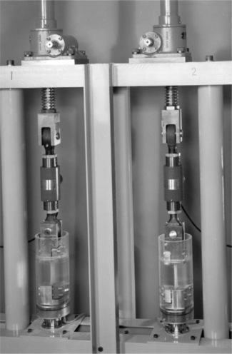
• a screw jack in series with a load cell (Fig. 13.14)
• self-stressing fixture (see Fig. 13.11).
The use of a mechanical test machine is not an economic option in most cases. A bank of small creep machines can be assembled at a considerably lower cost compared with the capital outlay involved with purchasing and operating such machines. Self-stressing fixtures, which are light and economic to produce and maintain, are particularly suited for field trials and for large batch testing. The large uncertainty associated with time-to-failure measurements, especially at high stress levels, will require either electromechanical or optical devices to monitor load or deformation in order accurately to determine time-to-failure. For short duration tests (i.e. static loads close to the maximum load at failure), load relaxation occurs and it is therefore necessary continually to adjust the manual screw jack on the creep frame or the loading spring on the self-stressing tube in order to maintain a constant load. The use of controlled mechanical test frames avoids this problem. Manually operated systems are best suited to long-term testing where loads are relatively low and load relaxation is minimal. Methods for accelerating the testing process that use mechanical loading tend to use stress levels that are significantly higher than stress levels used in design, thus the limiting design strains are reached in shorter times than in actual service.
The large uncertainty associated with static fatigue results, especially those obtained under hot/wet conditions, implies that the current approach of conducting three tests per stress level is inadequate and that considerably more data points are required to generate reliable creep rupture curves for engineering design purposes. Five (preferably 10) specimens per stress level with five stress levels per condition should provide a reasonable number of data points. For characterisation purposes, it is recommended that specimens are mechanically loaded at each of five stress levels (i.e. 80%, 70%, 55%, 40% and 25% of the short-term tensile strength of the material).
13.3.5 Artificial weathering
As the ultimate aim of accelerated ageing is to improve lifetime prediction under service conditions, the most appropriate conditions are those that match the service environment exactly. These are most easily obtained by naturally exposing specimens at outdoor exposure sites. The problem with this approach is that the exposure period required would have to be at least as long as the life expectancy of the product, and hence the need for accelerated (artificial) weathering procedures to simulate the effects of natural weathering in realistic timescales.
The predominant factors in climatic exposure are humidity, temperature and solar (UV) radiation. The severity of these factors will depend on geographical location, and need to be taken into account when designing composite structures. For marine applications, seawater and salt spray exposure also form part of the service environment. Accelerated weathering procedures39,49 generally involve cyclic exposure to a combination of salt spray, elevated and/or sub-zero temperatures, and ultraviolet (UV) radiation. At present, there is no universally agreed performance-based specification for accelerated weathering. Performance-based specifications are being developed by a number of recognised standards bodies including BSI, ISO, NACE (National Association of Corrosion Engineers) and customer end-users (e.g. Norsok). It is important to note that there is no ‘foolproof’ test that will provide an accurate prediction of service performance and life expectancy, or accommodates the wide range of climatic conditions experienced geographically.
Artificial weathering involves exposing test specimens to an artificial UV light source in a cabinet in which the temperature, humidity and water spray are controlled. The problem with this approach is determining synergistic effects (interactions) between the different parameters in the weathering process. The key parameter in all accelerated weathering apparatus is the UV light source, which should ideally simulate solar radiation. The main types of artificial light sources that are used are: carbon-arc, xenon-arc and fluorescent tube (see ISO 4892,50 ASTM D1499,51 ASTM D256552 and ASTM D432953).
Accelerated weathering standards tend to exclude the effect of sub-zero temperatures often experienced in practice or in external exposure testing. It is recommended that when selecting a procedure for accelerated weathering, consideration should be given to including a sub-zero temperature excursion. A freeze cycle (−20 °C for 24 h) has been included in ISO 2034054 in an attempt to produce more realistic results. The inclusion of the freeze cycle has been shown to produce results much more typical of those seen in practice or external exposure testing.49
The conditioning chamber and support equipment (i.e. racking) is constructed from corrosion resistant material (e.g. stainless steel). Specimens are supported within the test chamber using an open holding frame, which can be adjusted to allow double-sided or single-sided exposure. In order to simulate actual topside service conditions, only one surface is exposed to salt spray and UV radiation. A solid backing can be inserted into the holding frame for single-sided exposure. In addition to controlling irradiance, the test chamber should have controlled temperature, and if required controlled humidity. The chamber should also include facilities for the provision of salt spray or the formation of condensation on the specimen surfaces, or for immersion of the specimens in water. Irradiance at any position in the area used for the specimen exposure shall be at least 80% of the maximum irradiance. For some materials of high reflectivity, periodic repositioning of specimens is recommended to ensure uniformity of exposure (see ISO 489250).
13.4 Modelling and predictive analysis
This section provides a brief overview of different analytical modelling approaches for predicting material degradation and failure behaviour of composite materials in hostile environmental conditions. Although moisture diffusivity is of critical importance, the mathematical principles of Fickian and non-Fickian diffusion are not included in this chapter, as these are covered in detail in other publications.38,39,55 For more details on analytical models for predicting environmental degradation and failure of composites, see Brown and Greenwood,18 Broughton,56 Maxwell et al.,57 and Mensitieri and Iannone.58
Although a number of analytical models have been proposed for polymeric materials, relating the rate of property change with the level of degrading agent, they tend to be used for comparative purposes and not for design, as there is no conclusive evidence as to their universal validity. The Arrhenius relationship is one of the best known models for assessing the lifetime and is often used to predict the combined effects of temperature and time. It is particularly useful for the accelerated testing of polymers as it allows shortterm tests conducted at elevated temperatures to be used to assess long-term exposures at lower temperatures.
where K(T) is the reaction rate for the process (change of parameter with time), E is the activation energy, R is the gas constant (8.314 J/mole/K), T is the absolute temperature and A is an empirically derived constant. A plot of K(T) against 1/T will often yield a straight line with slope E/R, which can, with caution be extrapolated. Various forms of this relationship have been used to relate the rate of strength degradation with the rate of fluid uptake (i.e. diffusivity) for FRPs.
The transverse diffusivity D of neat resins and FRPs can be determined from the following relationship:
where D0 is a constant.
A similar relationship known as the Vant’Hoff expression is used to describe the dependence of water solubility on temperature:55
where ΔH is the enthalpy of water solubilisation and Sol0 is a constant.
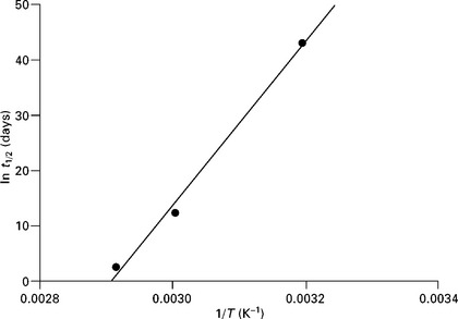
From a series of tests carried out at different ageing temperatures, it is possible to produce log-linear plots of changes in mechanical properties (stiffness and strength) with time. The time required for the property to decrease to a pre-determined or limit value (usually half its original value, half-life) at each temperature is then calculated from the fitted equations. The next step involves plotting the limit value as a function of the reciprocal of the ageing temperature (i.e. 1/T). The half-life t1/2 is related to the ageing temperature T as follows:
where C and D are material constants.
The half-life at service temperature can be estimated by extrapolation from the plot of ln t1/2 versus 1/T (a straight line) or by fitting the data to the above equation. It is important that the test temperatures are kept moderate (< 100 °C) to ensure that chemical reactions that occur at higher temperatures are avoided, and that the dominant mode of failure (i.e. single degradation mechanism) is identical at all temperatures and stress levels (see Fig. 13.15).
The relationship between half life, t1/2 and diffusivity, D, can be approximated by the following empirical relationship:
where constants A and B are derived from the line of best fit.
The above approach can be extended to determine the combined effect of temperature, moisture and stress on the failure time tf given by:
where C and b are constants, and S is the uniaxial stress. At constant temperatures, the log tf vs. S/T relation is a straight line.
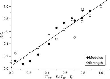
Strength and stiffness property degradation due to the effects of hygrothermal ageing can be approximated using a simple algebraic relationship of the form:59
where P denotes the material property (usually strength) at the test temperature T, Po is the initial property (un-aged) value of the dry material at room or reference temperature To, and Tgd and Tgw are the glass transition temperatures of dry and conditioned (i.e. wet) material. The exponent n is a constant empirically derived from experimental data. The relationship will only provide a rational solution when Tgd > To and Tgw > T.
The above relationship can be expected to apply to matrix dominated properties, such as transverse tension and flexure, and in-plane shear stiffness and strength properties, provided the fibre–matrix interface is not compromised (see Fig. 13.16). Fibre dominated properties are less sensitive to changes in matrix properties, and hence there is poorer agreement between experimental data and estimates made using this approach and the value of the exponent n will differ for the stiffness and strength data.
The above equation can be extended to include a component for cyclic fatigue as shown below:59,60
where k is obtained by curve-fitting experimental data and N is the number of cycles. The value of constant k will depend on the resin system, fibre type and orientation, and loading mode.
The wet glass transition temperature Tgw can be determined using the following quadratic relationship:59,60
where M is the moisture content (wt%), and A, B and C are constants obtained by curve-fitting experimental data.
For a number of materials, Tgw and Tgd are related as follows:23
where g is temperature shift (in K) per unit moisture absorbed.
The plasticising effect (i.e. reduction of Tg) of absorption of a diluent, such as moisture, into a composite laminate can be described by:61
where Tgm and Tgf are the glass transition temperatures of the fibre and matrix respectively, αm and αf are coefficients of thermal expansion, and Vf is the fibre volume fraction.
For matrix-dominated properties, strength and stiffness property degradation due to the effects of chemical species ingress can be expressed as:
where C is the concentration of ingress species, and C0 and Cmax denote initial and saturation concentrations.
A number of power law relationships have been used to describe weathering and corrosion behaviour of FRPs.18,19,30 An example is the semi-empirical relationship for uniform corrosion behaviour of FRP in chlorine dioxide environments:14,15
where Φ is the depth of corrosion (mm), B is a special factor (0 or 1) for the case of protective deposits on the surface, t is the time in service (years), α is a factor (0.5 to 1.0) dependent on the thickness and degree of degradation of the corroded surface layer, c is the concentration of chloride dioxide (g/1) and A is a material constant.
A further approach is to start with a relation of the form:
where y1 etc. represent the various factors or agents, which may cause degradation (e.g. dosage, intensity, temperature and humidity). Regression analysis techniques can then be used to find the significant agents and produce a model for the particular data in question. This is essentially an empirical approach. Alternatively, a mathematical form for the data could be found using neural networks or curve-fitting without giving consideration to the effect that individual agents have on the process. However, extrapolation of the data is then particularly dangerous.
In many weathering trials, results are available only for one set of conditions and strictly no extrapolation can be made for temperature, and the degradation is assumed to be independent of dosage rate. A number of factors make interpretation of property–time measurements difficult. These include:
• Strength may increase or decrease upon initial exposure to elevated temperatures. This may result from loss of volatiles, chemical cross-linking or relief of internal stresses.
• Long-term degradation rate may change during the ageing period. The ageing process may also change with temperature and exposure time.
• Statistical variability, which generally increases with exposure time, can introduce anomalous effects that make it difficult to differentiate the effects of key variables and to determine the ageing sequence. Rigorous statistical analysis is required to determine the precision (confidence limits) of the durability data.
• It is virtually impossible to duplicate service conditions using accelerated ageing procedures, particularly as realistic environments include large random variations in temperature, humidity and UV radiation.
The effects that ionising radiation have on the properties of plastics can be predicted using a time-temperature-dose rate superposition principle.62,63 This model is based on the Arrhenius relationship and allows plots of degradation vs. time obtained at different temperatures to be displaced along the time axis and superimposed upon one another using the following expression for the shift factor aT:
where Tref and T are the reference and service temperatures respectively. Three different methods for extrapolating from high dose rates to those more typically found in service are given in IEC 61244-2.64
Correlation factors
An empirical approach using simple algebraic expressions to relate loss of strength with the level of absorbed fluid (or degradation agent) in the composite. This approach is usually applicable only to a narrow range of materials (i.e. it is material specific) and conditions. It is assumed that a simple relationship exists between the mechanical properties of the conditioned material and the mechanical properties of the unconditioned material as a function of time and temperature.
Extrapolation of accelerated test data
Mechanical, thermal and chemical properties of FRPs change during the service life of a composite structure. Considerable timescales (months or years) are often involved, which for material qualification and design purposes is impractical. Hence the need for accelerated testing methods and prediction techniques to simulate long-term service conditions. The approach generally employed is to extrapolate the accelerated test data to service conditions, which is less demanding, using an acceleration factor. Mathematical functions that relate degradation, acceleration and time are often limited in their application. The effect of degradation differs between materials and different material properties. Degradation mechanisms are sensitive to small changes in the controlling parameters, such as temperature, stress and level of degradation agent. In addition, the interaction of degradation agents (i.e. synergistic effects) is generally not known with sufficient accuracy or certainty.
13.5 Optimising chemical resistance and prevention of failure
It is important to accurately define the environmental conditions that the composite structure must withstand and to select the fibre and resin system capable of operating under those conditions with no adverse effects. Factors to be considered include the chemical species present in the service environment, operating temperature and pressure, mechanical loading conditions and expected duration (i.e. service life) of exposure in the chemical environment. This should include any chemicals used in maintenance activities. Other factors, such as UV radiation and biological organisms should also be considered. Resistance of FRPs to chemicals and organic solvents can be improved by chemically modifying the resin system to reduce fluid permeation. Including inert fillers and additives, or increasing the crystalline phase (thermoplastics) will lower the volume of polymer that can be influenced by chemical or solvent ingress. Polymers containing protective additives, such as corrosion inhibitors, antioxidants, UV stabilisers and antimicrobials are available and users are advised to discuss their industrial requirements with resin manufacturers/suppliers.
The next step is to select a suitable protective coating (e.g. gel coat and protective paints) that will ensure long-term durability of the composite structure to the service conditions. Surface protection is critical to preventing surface degradation and ingress of chemical species (including water) into the composite and no matter how well a structure is designed, if the surface protection is inadequate, the composite substrate will degrade leading to premature failure. It is generally assumed that by maximising moisture resistance, resistance to attack from other chemical agents is also maximised.
The basic rules of good design of composite structures apply to most loading and environmental conditions. Coating (encapsulating) the exposed edges of composite structures, such as adhesively bonded joints and sandwich constructions with a chemical resistant sealant (e.g. silicones, fluorosilicones and polyurethanes) as appropriate to the service conditions, is advised. The presence of residual stresses induced by resin shrinkage and thermal expansion mismatch between reinforcement and resin matrix also pose a problem since complete removal is practically impossible. The presence of residual stresses will lower the FRP’s resistance to ESCC. Residual stresses can be minimised through good design and optimising the processing conditions.
13.6 Conclusions and future trends
Long-term performance under adverse conditions is an important issue from both a health and safety aspect and in terms of economic costs. The repair or replacement of a deteriorated part is both labour and capital intensive. As a consequence, there is a growing demand for manufacturers to guarantee the life expectancy of their products, particularly where inspection can be difficult or failure catastrophic. Whilst the life expectancy of products in non-demanding applications has traditionally been predicted from previous in-service experience (i.e. service conditions considered identical or similar to those for which data already exists), long-term or critical applications require a far better understanding of the failure mechanisms and the use of improved accelerated ageing regimes that simulate the degradation mechanisms and failure behaviour of FRPs in hostile environments.
The criteria used to assess environmental resistance include mechanical properties, such as Barcol hardness, flexural modulus and strength, dimensional stability, weight change and appearance (colour, gloss, crazing, fibre prominence, blister formation, loss of surface resin, etc.). Whilst mechanical properties and dimensional stability are quantitatively measurable, a number of the appearance criteria tend to be assessed in qualitative terms, and hence the question arises as to the reliability of the assessment. A major challenge is to ensure that performance testing for determination of chemical resistance (level of degradation) and its effect on failure behaviour is based upon a set of ‘quantitatively’ measurable criteria, thus avoiding qualitative or subjective assessment.
There are a number of non-invasive techniques available that can provide reliable and quantitative data relating to the degree of surface degradation (e.g. spectral reflectance or colour (spectrophotometry), surface reflectivity (gloss meter), hardness (Barcol hardness meter) and surface chemistry (Fourier transform infrared spectroscopy)) to mechanical performance.39 These test methods make it possible to produce measurable criteria for performance testing for determination of environmental resistance of composite materials. It may also be possible to use these techniques to quantify the level of degradation (i.e. a graduated scale) and provide realistic weighting factors.
The development of new measurement techniques, such as nanoindentation, atomic force microscopy (AFM), and scanning electrochemical microscopy, are expected to contribute to improved understanding of degradation mechanisms and failure behaviour of composites under hostile environmental conditions, particularly the role of interfacial properties on long-term ageing. These methods potentially offer rapid and/or low cost alternatives to mechanical testing for quality assurance (production) and environmental degradation assessment. It should be possible to miniaturise testing to enable rapid material selection and development and accelerated testing, thus reducing the need for large and time-consuming test programmes. No single ideal or universally applicable interfacial measurement method exists that can provide quantitative data for engineering or design purposes.
Future developments in structural health monitoring (SHM) and management are expected to include in-situ embedded sensors, such as Fibre Bragg gratings, for monitoring the chemical and structural integrity of composite structures from ‘cradle to the grave’. Real-time chemical sensors for monitoring in-situ moisture, pH and ionic or organic (e.g. processing) species in engineering structures should be a viable option in the near future. Non-destructive evaluation (NDE) techniques, such as X-ray computer micro-tomography (X-μCT) are beginning to provide considerable insight into the evolution of micro-damage and the role of environmental factors on failure initiation and growth in FRPs.
Recent developments in modelling approaches, such as fracture mechanics and molecular modelling, are expected to play a major role in improved design methodology for assessing long-term ageing. Fracture mechanics is proving a useful tool for predicting the failure of composite structures and future improvements are expected to include the effects of composite chemical degradation on static and dynamic performance in predictive analysis. It should also eliminate the need for large databases that are required when using stress analysis techniques.
Molecular modelling should lead to improved predictive analysis of failure behaviour of polymers, thus enabling designers and engineers to predict long-term performance in hostile environments. It may be possible to synthesise polymer molecules and their interactions with different chemicals and solvents using this approach, thereby eliminating a considerable amount of testing involved in evaluating the efficacy of the polymers and different additives (antioxidants, thermal stabilisers, UV stabilisers, etc.) to test environments. Hansen Solubility Parameters potentially provide a means of rapid chemical resistance evaluation for resin systems or at least useful information regarding the behaviour of resin systems (including additives) to a chemical reagent environment.65 This approach could be used in conjunction with combinatorial analysis to evaluate the effects of concentration levels and temperature on chemical resistance. A similar approach could be used to assess resistance to UV and high-energy radiation, and biological attack.
Note: There will still be a need to test entire substructures under end-use service conditions for safety conformance purposes, although the amount of data required from coupon testing should decrease with improvements in predictive modelling.
13.7 Sources of further information and advice
http://www.adhesivestoolkit.com
http://www.compositesuk.co.uk/
http://www.engineeringtoolbox.com
13.8 Acknowledgements
The background information included in this chapter owes considerable debt to a series of research programmes funded by the United Kingdom Department of Business, Innovation and Skills (National Measurement Office). This chapter has also benefited considerably from the technical support and advice provided by my colleagues Dr Tony Maxwell and Dr Graham Sims at the National Physical Laboratory, and Dr John Hartley (Exel Composites Ltd). The author gratefully acknowledges their contributions.
13.9 References
1. ISO 175, Plastics – Determining the effect of Liquid chemical including water.
2. Ehrenstein, W., Schmiemann, A., Bledzki, A., Spaude, R. Corrosion phenomena in glass-fiber-reinforced thermosetting resins. In: Cheremisinoff N.P., ed. Volume 1, Handbook of Ceramics and Composites. New York: Marcel Dekker, 1990.
3. Kootsookos, A., Mouritz, A. Seawater durability of glass- and carbon-polymer composites. Composites Science and Technology. 2004; 64:1503–1511.
4. Karbhari, V.M. Durability of composites in sub-zero and freeze-thaw conditions. In: Karbhari V.M., ed. Chapter 4, Durability of Composites for Civil Structural Applications. Cambridge: Woodhead Publishing, 2007.
5. Smith, C.S.Design of Marine Structures in Composite Materials. London: Elsevier Applied Science, 1990.
6. Pritchard, G.Reinforced Plastics Durability. Cambridge: Woodhead Publishing, 1995.
7. Castaing, P., Lemoine, L., Gourdenne, A. Mechanical modelling of blisters on coated laminates I – Theoretical aspects. Composite Structures. 1995; 30(2):217–222.
8. Castaing, P., Lemoine, L., Gourdenne, A. Mechanical modelling of blisters on coated laminates II – Experimental analysis. Composite Structures. 1995; 30(2):223–228.
9. Davies, P., Choqueuse, D. Ageing of composites in marine environments. In: Martin R., ed. Chapter 12, Ageing of Composites. Cambridge: Woodhead Publishing, 2008.
10. Choqueuse, D., Davies, P. Ageing of composites in underwater applications. In: Martin R., ed. Chapter 18, Ageing of Composites. Cambridge: Woodhead Publishing, 2008.
11. Sims, G.D., Broughton, W.R. Glass fiber reinforced plastics – Properties. In: Kelly A., Zweben C.H., eds. Chapter 5, Volume 2, Comprehensive Composite Materials. Oxford: Elsevier Science, 2000.
12. Broughton, W.R., Lodeiro, M.J., Maudgal, S., Accelerated test methods for assessing environmental degradation of composite laminatesNPL Report CMMT(A)251. Teddington: National Physical Laboratory, 2000.
13. Aveston, J., Sillwood, J.M. Long-term strength of glass reinforced plastics in dilute sulphuric acid. Journal of Materials Science. 1982; 17:3491–3498.
14. Bergman, G. A catastrophic failure of a component made of glass-fibre reinforced ester plastic in a pipeline for dilution of unbleached pulp in a storage tower. Proceedings of 9th International Symposium on Corrosion in the Pulp and Paper Industry, 26-29 May, 1998. [Ottawa].
15. Martin, R. Ageing of composites in the chemical processing industry. In: Martin R., ed. Chapter 17, Ageing of Composites. Cambridge: Woodhead Publishing, 2008.
16. Broughton, W.R., Lodeiro, M.J., Mulligan, D.R., Environmental degradation of unidirectional compositesNPL Report CMMT(A)250. Teddington: National Physical Laboratory, 2000.
17. Brown, R.P., Kockott, D., Trubiroha, P., Ketola, W., Shorthouse, J., A review of accelerated durability testsBrown R.P., ed. VAMAS Report No. 18, 1995. [Versailles Project on Advanced Materials and Standards].
18. Brown, R.P., Greenwood, J.H.Practical Guide to the Assessment of the Useful Life of Plastics. Shropshire: Rapra Technology Ltd, 2002.
19. Rider, A., Yeo, E.The chemical resistance of epoxy adhesive joints exposed to aviation fuel and its additives. Fishermans Bend, Victoria: Defence Science and Technology Organisation Platforms Sciences Laboratory, 2005. [Report No. DSTO-TR-1650].
20. Hogg, P.J., Hull, D. Micromechanisms of crack growth in composite materials under corrosive environments. Metal Science. 1980; 14:441–449.
21. Price, J.N. Stress corrosion cracking in glass reinforced composites. In: Roulin-Moloney A.C., ed. Chapter 12, Fractography and Failure Mechanisms of Polymers and Composites. London: Elsevier Science, 1989.
22. Chateauminois, A. Stress corrosion cracking in glass reinforced polymer composites. In: Martin R., ed. Chapter 4, Ageing of Composites. Cambridge: Woodhead Publishing, 2008.
23. Frost, S.R., Cervenka, A. Glass fibre-reinforced epoxy matrix filament-wound pipes for use in the oil industry. Composites Manufacturing. 1994; 5(2):73–81.
24. Ghotra, J.S. Oilfield FRP liners face corrosion and high temperatures. Polymers and Polymer Composites. 1999; 7(3):143–164.
25. Myers, T.J., Kytömaa, H.K., Smith, T.R. Environmental stress-corrosion cracking of fibreglass: lessons learned from failures in the chemical industry. Journal of Hazardous Materials. 2007; 142(3):695–704.
26. Jones, F.R., Rock, J.W., Bailey, J.E. The environmental stress corrosion cracking of glass-fibre-reinforced laminates and single E-glass filaments. Journal of Materials Science. 1983; 18:1059–1071.
27. ACI 440.3R-04, Guide to test methods for fibre-reinforced polymers for reinforcing or strengthening concrete structures.
28. Arnold, J.C. Environmental stress-crack initiation in glassy polymers. Trends in Polymer Science. 1996; 4:403–408.
29. Greenwood, J.H. Life prediction in polymers, 1997. [ERA Technology Report No. 97-0782R].
30. Wright, D.C.Environmental Stress Cracking of Plastics. Shropshire: Rapra Technology Ltd, 1996.
31. Tsotsis, T. Thermo-oxidative ageing of composite materials. In: Martin R., ed. Chapter 5, Ageing of Composites. Cambridge: Woodhead Publishing, 2008.
32. Ko, T.-H., Kuo, W.-S., Chang, Y.-H. Raman study of the microstructure changes of phenolic resin during pyrolysis. Polymer Composites. 2000; 21(5):745–750.
33. Mouritz, A.P. Durability of composites exposed to elevated temperature and fire. In: Karbhari V.M., ed. Chapter 6, Durability of Composites for Civil Structural Applications. Cambridge: Woodhead Publishing, 2007.
34. Wypych, G.Handbook of Materials Weathering. Toronto: ChemTec Publishing, 2003.
35. ASTM D1879, Standard practice for exposure of adhesive specimens to high-energy radiation, ASTM Book of Standards Volume 15.06.
36. ASTM G21, Standard practice for determining resistance of synthetic polymeric materials to fungi, ASTM Book of Standards Volume 14.04.
37. ISO 846, Plastics – Evaluation of the action of micro-organisms.
38. Duncan, B.C., Broughton, W.R.Absorption and diffusion of moisture in polymeric materials. Teddington: National Physical Laboratory, 2007. [NPL Measurement Good Practice Guide No. 102].
39. Broughton, W.R., Maxwell, A.S.Accelerated environmental ageing of polymeric materials. Teddington: National Physical Laboratory, 2007. [NPL Measurement Good Practice Guide No. 103].
40. Tsotsis, T.K. Long-term thermo-oxidative aging of composite materials: experimental methods. Journal of Composite Materials. 1995; 29(3):410–422.
41. ASTM D4102, Standard test method for thermal oxidative resistance of carbon fibers, ASTM Book of Standards Volume 15.03.
42. ISO 62, Plastics – Determination of water absorption.
43. ASTM C581, Standard practice for determining chemical resistance of thermosetting resins used in glass-fiber-reinforced structures intended for liquid service, ASTM Book of Standards Volume 08.03
44. BS EN 13121-2, GRP tanks and vessels for use above ground – Part 2: Composite materials – Chemical resistance.
45. BS 4994, Design of construction vessels and tanks in reinforced plastics.
46. Turnbull, A., Maxwell, A.S.Test methods for environment stress cracking of polymeric materials. Teddington: National Physical Laboratory, 1999. [NPL Technical Review No. 3].
47. BS 5480-2, Specification for glass reinforced plastics (GRP) pipes and fittings for use for water supply and sewerage.
48. ASTM D3681, Standard test method for chemical resistance of ‘fibreglass’ (glass-fiber-reinforced thermosetting resin) pipe in a deflected condition, ASTM Book of Standards Volume 08.03.
49. Mitchell, M.J. Testing of offshore systems – is there a realistic testing scenario or is there still work to be done?. Proceedings of NACE 2004 Corrosion Conference ‘Progress in Offshore Coatings’, New Orleans, March, 2004.
50. ISO 4892, Plastics – Methods of exposure to laboratory light sources.
51. ASTM D1499, Standard practice for filtered open-flame carbon-arc exposures of plastics, ASTM Book of Standards Volume 08.01.
52. ASTM D2565, Standard practice for xenon-arc exposure of plastics intended for outdoor applications, ASTM Book of Standards Volume 08.01.
53. ASTM D4329, Standard practice for fluorescent UV exposure of plastics, ASTM Book of Standards Volume 08.02.
54. ISO 20340, Paints and Varnishes – Performance requirements for protective paint systems for offshore and related structures.
55. Helbling, C., Karbhari, V.M. Durability of composites in aqueous environments. In: Karbhari V.M., ed. Chapter 3, Durability of Composites for Civil Structural Applications. Cambridge: Woodhead Publishing, 2007.
56. Broughton, W.R., Analytical models for assessing environmental degradation of unidirectional and cross-ply laminatesNPL Report MATC(A)1. Teddington: National Physical Laboratory, 2005.
57. Maxwell, A.S., Broughton, W.R., Dean, G., Sims, G.D.Review of accelerated ageing methods and lifetime prediction techniques for polymeric materials. Teddington: National Physical Laboratory, 2005. [NPL Report DEPC MPR 016].
58. Mensitieri, G., Iannone, M. Modelling accelerated ageing in polymer composites. In: Martin R., ed. Chapter 9, Ageing of Composites. Cambridge: Woodhead Publishing, 2008.
59. Chamis, C.C., Lark, R.F., Sinclair, J.H. Integrated theory for predicting the hygrothermomechanical response of advanced composite structural components. In: Vinson J.R., ed. Advanced Composite Materials – Environmental Effects. Conshohocken, PA: American Society for Testing and Materials; 1978:160–192. [ASTM STP 658].
60. Chamis, C.C., Murthy, P.L.N. Simplified procedures for designing bonded composite joints. Journal of Reinforced Plastics and Composites. 1991; 10:29–41.
61. Eckold, G.Design and Manufacture of Composite Structures. Cambridge: Woodhead Publishing, 1994.
62. Gillen, K.T., Clough, R.L. Time-temperature-dose rate superposition: a methodology for extrapolating accelerated radiation aging data to low dose rate conditions. Polymer Degradation and Stability. 1989; 24(2):137–168.
63. Gillen, K.T., Clough, R.L. Degradation mechanisms and accelerated aging test design. Polymer Materials Science Engineering. 1985; 52:592–597.
64. IEC 61244-2, Determination of long-term radiation ageing in polymers – Part 2: Procedures for predicting ageing at low dose rates.
65. Chanda, M., Roy, S.K. Plastics Fundamentals, Properties and Testing. Plastics Engineering Series. CRC Press, Abingdon, 2009. [Taylor & Francis Group].
13.10 Appendix: standards
13.10.1 ISO standards
ISO 62 Plastics – Determination of water absorption.
ISO 75 Plastics – Determination of temperature of deflection under load.
ISO 175 Plastics – Determining the effect of liquid chemical including water.
ISO 176 Determination of loss of plasticisers – Activated carbon method.
ISO 177 Plastics – Determination of migration of plasticiser.
ISO 291 Plastics – Standard atmospheres for conditioning and testing.
ISO 483 Plastics – Small enclosures for conditioning and testing using aqueous solutions to maintain relative humidity at constant value.
ISO 554 Standard atmospheres for conditioning and/or testing – specification.
ISO 846 Plastics – Evaluation of the action of micro-organisms.
ISO 877 Plastics – Determination of resistance to change upon exposure under glass to daylight.
ISO 1137 Plastics: Determination of behaviour in a ventilated tubular oven.
ISO 2578 Plastics: Determination of time/temperature limits after exposure to prolonged action of heat.
ISO 2579 Plastics – Instrumental evaluation of colour differences.
ISO 3205 Preferred test temperatures.
ISO 3557 Plastics – Recommended practice for spectrophotometry and calculation of colour in CIE systems.
ISO 3558 Plastics – Assessment of the colour of near-white or near-colourless materials.
ISO 4599 Plastics – Determination of resistance to environmental stress cracking (ESC) – Bent strip method.
ISO 4582 Plastics – Determination of changes in colour and variations in properties after exposure to daylight under glass, natural weathering or laboratory light sources.
ISO 4600 Plastics – Determination of environmental stress cracking (ESC) – Ball and pin.
ISO 4607 Plastics – Methods of exposure to natural weathering.
ISO 4611 Plastics – Determination of the effect of exposure to damp heat, water spray and salt.
ISO 4892 Plastics – Methods of exposure to laboratory light sources.
ISO 6252 Plastics – Determination of resistance to environmental stress cracking (ESC) – Constant tensile stress method.
ISO 6721 Plastics – Determination of dynamic mechanical properties.
ISO 9370 Guide for the instrumental determination of radiant exposure in weathering tests.
ISO TR 9673 Solar radiation and its measurements for determining outdoor weather exposure levels.
ISO 11507 Paints and varnishes – Exposure of coatings to artificial weathering – Exposure to fluorescent UV and water.
ISO 11357 Plastics – Differential scanning calorimetry.
ISO 11403 Acquisition and presentation of comparable multi-point data – Environmental influences on properties.
ISO 14692 Petroleum and natural gas industries – Glass reinforced plastic (GRP) piping.
ISO 16770 Plastics – Determination of environmental stress cracking (ESC) of polyethylene – Full-notch creep test (FNCT).
ISO 20340 Paints and Varnishes – Performance requirements for protective paint systems for offshore and related structures.
ISO 22088 Plastics – Determination of resistance to environmental stress cracking (ESC).
13.10.2 BSI/EN standards
BS EN 2378 Fibre reinforced plastics – Determination of water absorption by immersion in demineralised water.
BS EN 2489 Fibre reinforced plastics – Determination of the action of liquid chemicals.
BS EN 2823 Fibre reinforced plastics – Determination of the effect of exposure to humid atmosphere on physical and mechanical characteristics.
BS 4994 Design of construction vessels and tanks in reinforced plastics.
BS 5480 Specification for glass reinforced plastics (GRP) pipes and fittings for use for water supply and sewerage.
BS EN 13121:2 GRP tanks and vessels for use above ground – Part 2: Composite materials – Chemical resistance.
13.10.3 ASTM standards
C581 Standard practice for determining chemical resistance of thermosetting resins used in glass-fiber-reinforced structures intended for liquid service.
D543 Standard practices for evaluating the resistance of plastics to chemical reagents.
D570 Standard test method for water absorption of plastics.
D1203 Standard test methods for volatile loss from plastics using activated carbon methods.
D1435 Standard practice for outdoor weathering of plastics.
D1499 Standard practice for filtered open-flame carbon-arc type exposures of plastics.
D1653 Standard test method for water vapour transmission of organic coating films.
D1693 Environmental stress-cracking of ethylene plastics.
D1712 Standard practice for resistance of plastics to sulfide staining.
D1879 Standard practice for exposure of adhesive specimens to high-energy radiation.
D2290 Standard test methods for tensile, compressive, and flexural creep and creep-rupture of plastics.
D2565 Standard practice for xenon-arc exposure of plastics intended for outdoor applications.
D3045 Standard practice for heat aging of plastics without load.
D3681 Standard test method for chemical resistance of ‘fibreglass’ (glass fibre reinforced thermosetting resin) pipe in a deflected condition.
D4102 Standard test method for thermal oxidative resistance of carbon fibers.
D4329 Standard practice for fluorescent UV exposure of plastics.
D4364 Standard practice for performing outdoor accelerated weathering tests of plastics using concentrated sunlight.
D5229 Standard test method for moisture absorption properties and equilibrium conditioning of polymer matrix composite materials.
E96 Standard test methods for water vapour transmission rate of materials.
G21 Standard practice for determining resistance of synthetic polymeric materials to fungi.
G24 Standard practice for conducting exposures to daylight filtered through glass.
G156 Standard practice for selecting and characterizing weathering reference materials used to monitor consistency of conditions in an exposure test.
G178 Standard practice for determining the activation spectrum of a material (wavelength sensitivity to an exposure source) using the sharp cut-on filter or spectrographic technique.