
7Audio and Video Chaotic Encryption and Communication Technology
With the development of network communication, Internet provides an amount of information services to users every day. Because the foundation protocol of Internet is not completely secure, when unencrypted information transmits on the network, it will be directly exposed to the entire network, which is a great threat to information security, especially for audio and video communications, such as eavesdropping, call tracking, phone hijacking, and denial of service. Therefore, we should improve network design and also take a variety of technologies, such as voice encryption technology, to ensure the safety of audio and video communications. With the deepening of chaotic applied research, promising progresses have been made on chaotic cryptosystem [143–146], and a new path has been opened to improve the information security. Thus, it is significant to combine the traditional data encryption algorithm, video image standard MPEG and H.264 with chaos and to apply it in real-time communication. This chapter focuses on audio and video real-time encryption and communication technology based on chaos.
7.1Principle of Real-Time Voice Encryption Communication
In Chapter 6, we studied the chaotic encryption principle of static data file, and it mainly used the idea of computer process synchronization to realize synchronization of chaotic iterative system. The starting parameters and synchronization strategy themselves are passwords, so it need not use complex physical chaotic synchronization or control method. But if you want to achieve real-time transmission of encrypted data stream, chaotic synchronization is an unavoidable problem. Here, we adopt the network adaptive communication environment (ACE), which is a cross-platform, to implement the real-time transport protocol (RTP)/RTP control protocol (RTCP) and combine the chaotic encryption algorithm with the extended Data Encryption Standard (DES) encryption algorithm. A voice encryption communication system, which is adaptable for network real-time transmission, is developed by equal interval drive synchronous method.
7.1.1Principle of Digital Encryption Communication System
Although the sequence cipher system, block cipher system, and public key cryptosystemcan be used for encryption of digital signal, researchers have certain requirements for the real time and quality (measured by bit error rate) of information transmission in practice. Therefore, an appropriate cryptosystem must be selected according to the specific digital communication system and the corresponding transmission quality of channel [147].
Generally speaking, because there are error diffusion and delay for block cipher system, block cipher system is applied in the occasions of good channel transmission quality or containing data retransmission function. Due to its huge amount of computation for public key system, it is difficult to meet the real-time requirements of voice communication system in the present technology level. Therefore, the public key system is usually not directly applied to real-time data stream encryption. Further-more, because of the characteristics of small delay and no error diffusion, sequence cipher system is widely used in digital communication system, which is suitable for the quality of all kinds of channels [148]. The principle of digital encryption and communication system based on the sequence cipher system is shown in Figure 7.1.
Digital voice encryption communication system mainly includes source coding/decoding, encryption/decryption operator, cipher sequence generation, cipher synchronization control, and synchronization insertion/detection.
Through sampling, quantization, and encoding (including compressed encoding), source coding/decoding module at the sender transforms the original analog signal into binary digital sequence and inputs them to the encryption device. This module recovers the binary sequence to analog signals at the receiver.
Encryption/decryption operation generally uses the XOR operation. At the sender, ciphertext is obtained by the XOR operation of the binary digital sequence from source encoding module with secret key sequence. At the receiver, the binary plaintext sequence is recovered by the XOR operation to secrete key sequence.
The main function of the cipher sequence generation module is to generate secrete key sequences for encryption or decryption, which is the key part of reliability in digital encryption and communication system, including the encryption sequence generation module (it is used to encrypt the plaintext on the sender) and the decryption sequence generation module (it is used to decrypt the ciphertext at the receiver).

The cipher synchronization control module mainly generates a cipher synchronization signal to update the status of secrete key sequence at both the receiver and the sender. To ensure the cipher synchronization in the encryption and decryption processes, the secrete key (initial conditions or parameters of chaotic system) must be the same.
At the sender, synchronous insertion/detection module inserts the cipher synchronization signal into the corresponding position of ciphertext stream. At the receiver, digital information stream is detected in real time. Once the cipher synchronization signal is found, it is extracted from the information stream, and its message key is sent to the decryption sequence generation module to update its status and the noncipher synchronization information is transmitted transparently at the same time.
7.1.2Real-Time Voice Encryption and Communication System
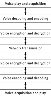
Point-to-point (P2P) real-time voice chaotic encryption and communication system is shown in Figure 7.2. At the transmitter, first, analog signal is transformed into binary plaintext data stream through the A/D converter. Then, chaotic sequence generator generates a chaotic pseudorandom sequence to XOR the plaintext data stream, and a ciphertext data stream is produced. Subsequently, ciphertext is sent to the network channel according to the network protocol. At the receiver, a chaotic sequence, which is synchronous with the sender, is used to decrypt the ciphertext sequence by the XOR operation to restore the binary voice stream. Finally, through D/A converter, the binary voice stream is returned to the analog voice signal and it is broadcasted.
The encryption process at the sender is expressed as
where M (n) is the voice sequence, E(n) is the chaotic sequence, S(n) is the ciphertext sequence, and ⊕ is the XOR operator.
The decryption process at the receiver is the inverse process of encryption, i.e.

Figure 7.2: Principle block diagram of the voice chaotic encryption system.
where R(n) is the ciphertext on the receiving side and R(n) = S(n) for an ideal channel. D(n) is the chaotic sequence on the receiving side. M′(n) is the decryption output. Obviously, when both sides of the system are synchronized, i.e. D(n) = E(n), then M′(n) = M (n). So the voice encryption communication is achieved.
Obviously, the key of realizing the encryption communication is to realize the synchronization of chaotic sequence generators between the receiver and the sender. Because the object of computer processing is digital signal, the existing analog synchronization method cannot meet the requirements of network transmission. Combined physical synchronization with computer programming techniques, the equal interval drive synchronization method is proposed, which is suitable for computer network communication. Theory analysis and experimental results show that this method has strong fault tolerance capability.
7.1.3Cipher Synchronization Technology
Cipher synchronization is the key technology in the digital real-time encryption and communication system. In practice, to ensure the strict consistency of the starting points of system communication on the encryption and decryption sides, the cipher synchronization must be established before encryption and communication. The order of cipher synchronization is shown in Figure 7.3.
First, bit synchronization is set up for the system. It can be realized by the clock provided by the source terminal or channel transmission device, and also can be achieved by extracting the clock from the source terminal or the digital stream provided by the transmission device. Second, cipher synchronization is established. After the establishment of bit synchronization of communication system, the sender sends the cipher synchronization signal (including the synchronization head and the message key) to the other side to make the cipher generator of two sides to work synchronously. For some real-time encryption communication systems, it needs to establish frame synchronization (group synchronization) before the establishment of cipher synchronization. Finally, ciphertext sequence is transmitted. After the code synchronization signal of the sending side is transmitted, the ciphertext sequence is transmitted immediately. The encrypted sequence is obtained by the corresponding encryption algorithm, which is based on the same message key as the receiving side. Receiver extracts the message key from the cipher synchronization signal and injects it into the cipher generator. Simultaneously, the cipher generator generates the cipher sequence, which makes the decryption cipher sequence and the encryption cipher sequence to work in the synchronized state.

Cipher synchronization methods include continuous synchronization, unique initial synchronization, self-synchronization, and special synchronization. In this section, a continuous synchronization method is adopted to realize the cipher synchronization of encryption communication. The continuous cipher synchronization is to send a cipher synchronization signal with a fixed interval, and it has advantages, such as allowing the lag to enter, plaintext beyond function and multiple communication ways. It is worth noting that the transmission cipher synchronization information may reduce the transmission rate, but the security and reliability of system are improved.
7.2Real-Time Data Stream Encryption Algorithm
In real-time voice encryption algorithm, the traditional DES cryptography is no longer safe [149]. Researchers proposed various improved algorithms, such as 3DES based on secrete key expansion, but its key space is still limited. Therefore, 3DES encryption method based on chaotic map is adopted to guarantee the security of data stream. Specifically, synchronized chaotic map systems are set on the encryption and decryption sides, the secrete key of each data packet is generated by chaotic system to realize real-time encryption and transmission of voice data.
7.2.13DES Encryption Algorithm
3DES is defined by the National Institute of Standards of Technology (NIST) in 1999 [150]. 3DES defines two kinds of work modes. In the first mode, secrete key k1 is used to encrypt the 64-bit plaintext. Then secrete key k2 is used for the second encryption. Finally, secrete key k3 is used for the third encryption, and the ciphertext is outputted. This pattern is called DES-EEE, which is expressed as
where M is the plaintext and C is the ciphertext. This encryption mode extends the key space into 168 bits. In the second mode, k1 is used to encrypt the 64-bit plaintext. Then the result is decrypted by k2. Finally, k3 is used to encrypt the decryption result. This pattern is called DES-EDE, which is expressed as
where M is the plaintext and C is the ciphertext. This encryption mode extends the key space into 112 bits. In the encryption process, secrete keys k1, k2, and k3 have three options as follows.
Here, we adopt the second mode of 3DES, and the second way of secrete key. The encryption model is shown in Figure 7.4. 64-bit data is encrypted with k1 to obtain the ciphertext first. Then k2 is used to decrypt the result to obtain “plaintext,” and then k3 (k1) is used to encrypt the decryption results. Obviously, after removing the bits of eight times from the 128-bit secrete key, there are 112-bit secrete key, and the key space is 2112. The only disadvantage of this method is that three times ordinary DES encryption of the algorithm spends about three times implementation time. But it is acceptable for very cheap computing resource at present.
7.2.2Encryption Algorithm Based on 3DES and Chaotic Map
Chaotic dynamics system can be used in many application fields, such as digital communication and multimedia data security [151].
Similarly, logistic map studied in the sixth chapter is defined as
where μ ∈ (0, 4] and xn ∈ (0, 1). When 3.5699 . . . < μ ≤ 4, it is chaotic. According to the statistical analysis in Section 3.1.1, the chaotic sequence of logistic map {xn, n = 0, 1, 2, 3, . . .} is nonperiodic and nonconvergent, and it is very sensitive to initial conditions.
DES algorithm with key expansion (3DES) is the core of real-time voice encryption algorithm, and the secrete keys of encryption and decryption are generated by two synchronized chaotic systems (logistic map). The encryption model is shown in Figure 7.5. Ki is the secrete key of encryption and decryption of each data packet, which is generated by the logistic map. x0 and μ are the initial condition and parameter of logistic map, and that is the secrete key transmitted in the secret channel.
When the logistic map is used to generate secrete key, two problems need to be solved. One is how to transform the generated sequence into a 64-bit secrete key, and another is how to synchronize two chaotic maps to ensure that each data packet to obtain the right secrete key for decryption. Here, the double precision type is used to store the initial condition x0 and parameter μ of logistic map. The double type is 8 bytes (64 bits) in Win32. So it can be used as the secrete key of DES. The secrete key of 3DES is obtained by iterating the logistic map two times to produce 64-bit double data. The storage format of double data is shown in Figure 7.6.

Figure 7.4: 3DES encryption model.


In this figure, the 0th bit is sign bit. The first bit to the 11th bit is 11-bit order code, and the 12th bit to the 63rd bit is 52-bit mantissa. The calculation method of double type data is
where i is the sign bit, e is the order code, and f is the mantissa.
The range of iteration value is (0, 1), and thus e ∈ [0, 1022]. The number of its valid bits is still 11, and its sign bit is unchanged. So the total number of valid bits in double type is 63. The iteration space is 2×(263–252), in which multiplying by 2 represents two 64-bit iterations, and minus 252 means to subtract it at e = 1, 023. Because the number of 8 times in DES algorithm is only used as check bit, the key space of an actual data packet is about 2112.
To realize synchronization between two chaotic systems, the iteration number of system is saved in the header of each encrypted data packet as plaintext. According to the iteration number in the header, the receiver iterates the logistic map to produce decryption key and uses it to decrypt. In practice, the former packet of secrete key can be memorized to reduce iterations. Since the number of iterations is transmitted as plaintext in the header data, it may be intercepted by third party. But the decryption key cannot be obtained without the initial condition and parameter of this map. As long as the synchronous data in the header is received correctly, the synchronization can be achieved.
Shannon proves that one-time pad is unable to be deciphered, and 3DES has high security level. So, the encryption algorithm has a high security. Corresponding to real-time voice communication, if a single data packet is deciphered, it will not affect the entire transmission process. Because the pseudorandomness of chaos leads to the condition that secrete keys are relatively independent, so that each data packet has the same crack strength to ensure the security of data communication to the maximum extent.
7.2.3Network Synchronization Method
Synchronization is the key to achieve real-time data stream encryption. If transmission errors of the sequence generated by the logistic map occur, it will cause the failure of synchronization of encryption and decryption. Here, a synchronization scheme is designed, which fully depends on the network to achieve self-synchronization as shown in Figure 7.7.
It can be seen that the processes of encryption and decryption are symmetrical, and the synchronization between them is completely dependent on the error-free transmission on the network. Tests show that the synchronization of encryption and decryption is good in the beginning of a few minutes. However, when the time is longer (usually between 5 and 10 min), the phenomenon of out of step will suddenly happen, so that the entire decryption is destroyed, and it cannot be restored. On one hand, the transmission control protocol (TCP) cannot be fully realized error-free transmission. On the other hand, both the encryption and decryption sides do not have fault-tolerant ability, and a little mistake could waste all the previous efforts. After further analysis, it is found that the above scheme is not without merit, because it is synchronized at the beginning of a few minutes. That is to say, we could establish an error tolerance and error correction mechanism to make the less probability of data error. But how do you know when the data is wrong, unless the server sends the voice data and error correction code at the same time. Otherwise, it is not known. However, considering the particularity of voice information, it does not necessarily have the ability of error correction as long as the fault is tolerant. In real life, when a sentence does not listen to the other side, he can ask the other side to say it again. Based on the above analysis, an equal interval drive synchronization scheme is designed in Figure 7.8.

Figure 7.7: Network self-synchronization scheme.


Compared with Figure 7.7, the synchronous insertion and synchronous detection module are added to the system in Figure 7.8. In the encryption side, the drive code of chaotic sequence (number of iterations) is inserted into the header of ciphertext data packet, and it is sent with the ciphertext data packet. In decryption side, the driver code is taken out by the synchronous detection module, and it is used to drive the chaotic sequence generator to generate secrete key to decrypt the cipher sequence, and the secrete key is consistent with that of the sender.
The fault tolerance capability of the above synchronization scheme is analyzed. We will consider all errors that may occur in the network transmission. The transmission process is shown in Figure 7.9.
The upper part of Figure 7.9 is the data sent to the network, where Di is the drive code and Ei is encrypted voice stream. The middle data is read from the Internet on the decryption side, where Di is the drive code and Ei is the encrypted voice stream. The bottom data is the decrypted voice data stream. Obviously, transmission errors are classified into the following categories:
- Drive code is transmitted in error. For instance, D1 is transmitted to Dx.
- Encrypted voice data is transmitted in error. For instance, E2 is transmitted to Ex.
- Drive code is lost. For instance, D4 is lost.
As shown in Figure 7.9, the first and second errors only affect one data packet of voice stream. When D2 or D3 is received on the decryption side, all contacts between Ex and Dx will be cut off. D3 is used to iterate two values to generate two double precision decryption sequences to complete decryption, while the encryption side also use D3 to generate two double-precision encryption sequence to accomplish encryption. So the encryption and decryption sequences are same, and the synchronization of encryption and decryption is realized. For the third case, it only affects one voice data packet too. When the correct driver code is received, it will return to the state of synchronization. After a long period of testing, it is proved that this scheme is feasible and can keep synchronization of encryption and decryption in infinite time. Although transmission errors occur accidentally in the middle, they will not affect the whole process of call. There is no security risk to expose the drive code to the outside because the following n-bit sequence does not have the possibility to be predicted without knowing the values of parameter μ and initial condition x0.
In general, the main idea of this synchronization scheme is to make use of the tiny bit error rate provided by network transmission protocol. Regardless of whether there is a bit error, the decryption side is forced to make a new synchronization at set intervals (it is very small). That is to say, the synchronization of the entire call time is changed to the synchronization of many times. Even if a period of time is not synchronized, it will only affect the data in this segment, and the entire call is not affected.
7.2.4Security Analysis of Real-Time Voice Encryption System
Dachselt et al. [152] studied the cryptanalysis method of an encryption system based on discrete chaotic map. Yang et al. [153] thought that analog chaotic encryption system is difficult to resist the return mapping attack. Zhou et al. [154] reported that simple chaotic encryption system did not have a high security level and proposed an improved algorithm by increasing the number of iterations. Here, we design an encryption system, which combines the block encryption algorithm with chaotic encryption algorithm, and the security of system is analyzed by the following cryptanalysis methods:
- The system has the ability to resist the brute-force attack. Because the encryption system is not dependent on the encryption scheme or algorithm, but relies on the secrete key. It is worth noting that secrete key signal generator could not be open, and some literatures about cryptanalysis often adopted this design principle. This is particularly important for the advantages of chaotic encryption. The previous analysis indicates that the system adopts the improved DES algorithm, i.e. 3DES, to encrypt data packets, and its key space is 2112. Since the secrete key of system is generated by chaotic map, the secrete key of each data packet is alterative. Therefore, the key space of each data packet is 2112, which is large enough to resist brute-force attack. Even if the breaker acquires the equation of chaotic map, it is difficult to determine its parameters and initial conditions.
- The system has the ability to resist the chosen plaintext and chosen ciphertext attacks. As the secrete key of system is generated by the chaotic map, and the secrete key sequence is unpredictable, there is no one corresponding to the plaintext and the ciphertext. The ciphertexts corresponding to the same text are different and not related. So, the chaotic encryption system is equivalent to one-time pad mechanism, and Shannon has proved that it is unable to be deciphered.
- The system has the ability to resist spectrum analysis. Spectrum analysis is one of cipher cracking methods often adopted by cryptanalysts. However, because chaotic signal with wide frequency spectrum is similar to the noise, attackers cannot get any useful information about the encrypted signals through the spectrum analysis method. Therefore, this method has no effect on the output signal of chaotic encryption system. In addition, there is no correlation between the chaotic encrypted signal and the original signal, which ensures the security of encryption system. Any deciphered error to the ciphertext is amplified by the chaotic system, and it also improves the encryption intensity.
7.3Realization of Real-Time Voice Encryption System
7.3.1Structure of Real-Time Voice Encryption System
Based on ACE, RTP, and real-time encryption scheme, a real-time network voice encryption system is developed. Its structure is shown in Figure 7.10. The whole system consists of the following modules: voice acquisition/broadcast module, en-coding/decoding module, encryption/decryption module, and transmission module. As a real-time system, it is necessary to have a real-time voice acquisition and broadcast module. Encryption operation is achieved by using real-time encryption scheme. The communication protocol is based on RTP, which is transmitted on the Internet through the network layer and physical layer.
Figure 7.10 is a P2P communication model. Multicast function is realized by using RTP in voice transmission module. So, it is not only used in P2P communication, but also can be used in many-to-many communication. The bidirectional arrows in the figure represent the bidirectional data stream.
The realization of each module is independent of each other. It communicates with other module by interfaces. Each module is realized by the static library (.lib file), such as VoiceIO.lib of voice capture/broadcast module, Codec.lib of voice encoding/decoding module, Crypto.lib of voice encryption/decryption module, and RTPLib.lib of voice transmission module. These static libraries can be used independently or in combination with external applications, which greatly enhances the reusability of each module.
Speech acquisition module records the voice data collected by microphone through sound card, while speech broadcast outputs the speech data by sound card and speaker. The signals via microphone and speaker are analog signals, and signals of computer processing and transmission are digital signals. So the role of sound card is to achieve the mutual conversion of the two kinds of signals. The conversion process is related to the sampling frequency, encoding bits, and channels number. Human voice frequency is about 10 kHz. According to the sampling theorem, the sampling frequency is chosen as 22.050 kHz. Here, the system uses 16-bit memory Pulse Code Modulation (PCM) encoding, single channel.
Encoding/decoding module employs A-law compression encoding. Through this method, 16-bit linear code obtained by sampling can be converted to 8-bit nonlinear encoding. In this way, the transmission rate can be reduced by half.
Encryption/decryption module uses the encryption scheme based on the 3DES (extended DES) and chaotic system (logistic map), and block encryption algorithm is used in the stream communication. Logistic map, synchronization process, and 3DES encryption algorithm are packaged together, and only two interfaces of encryption/decryption are exposed to external. As described in Section 7.2.3, chaotic synchronization is accomplished by the header of data packets, which include the iteration number of logistic map, and the iteration number is directly used to generate the secrete key for encryption/decryption.

Network transmission module is based on RTP, and the network application model is shown in Figure 7.11. User Datagram Protocol (UDP) protocol is used in the RTP transport layer to achieve simple multicast function. The speech transmission module exposes the RTP_Session class to outside, and inside of this module is the specific implementation of RTP.
The RTP is a transport protocol for multimedia data stream on Internet. RTP is defined in the transmission conditions of P2P or one-to-many, and its purpose is to provide time information and achieve flow synchronization. RTP usually uses UDP protocol to transmit data, but RTP can also work on other protocols such as TCP or Asynchronous Transfer Mode (ATM). When an application starts an RTP session, two ports are used, one for RTP and the other for RTCP. RTP itself does not provide flow control or congestion control, but it provides these services by RTCP. RTP algorithm is usually not implemented as an independent network layer, but as a part of the application code. During the RTP session, the participants periodically transmit RTCP packets. The RTCP packet contains some statistical information such as the number of sending packets and lost packets, so that the server can use these information to dynamically change the transmission rate, and even change the effective load type. With the use of RTP and RTCP, they can optimize the transmission efficiency by effective feedback and minimum overhead, which is especially suitable for the transmission of real-time data on Internet.
The software running platform of voice encryption system based on RTP is Windows 2000 professional or Red Hat Linux 9.2. The development tools are Rose Rational 2000, C++ Visual 6, g++, and emacs. The third library is ACE 5.4 and Standard Template Library. The software framework is shown in Figure 7.12.
7.3.2Real-Time Transmission Protocol and Its Data Structure
The RTP data packet is composed of two parts, the RTP header and the continuous media data with indefinite length, and its format is shown in Figure 7.13, where V represents the version number of RTP specified as 2. P is the padding bit. When P = 1, it indicates that the data packet tail is loaded with a nonload information, which can be used to encrypt or notify the bottom layer protocol. A data unit has several RTP packages. X is an extension bit, and when X = 1, it indicates that the RTP header is attached to an extended header with variable length. M is used to mark the important event in the data stream, such as the frame boundary. Load type is used to identify the type of media in the receiver. If it is the encoding data, it determines the decoder of the receiver. The serial number is used to identify the order of the RTP packets sent by the sender, and the serial number increases by 1 when an RTP packet is sent. The receiver detects the loss situation of data packet by serial number, and then the packet is recovered after reordering. The time stamp reflects the sampling interval of RTP packet in the first byte. The sampling frequency must be derived from a clock with linear growth, and the clock frequency usually depends on the data transmission format. If the RTP packet is periodically generated, then the sampling frequency is determined by the sampling clock, rather than the system clock. The synchronization source identifier (SSRC) identifies the synchronization source, which is randomly generated, and the SSRC identifier of two synchronization sources in the same RTP session is different. Contributing source identifier (CSRC) can contain 0–15 items. Contributing source refers to a new combination of RTP packets after the procession of mixer when one or more of RTP data packets are received from the synchronous source. The mixer is used as the SSRC of the combination RTP packet, and all the SSRC are transmitted to the receiver as a special source identifier, so that the receiver knows all the SSRC of RTP packets.

Another protocol is RTCP, which is usually used with RTP, and it can be used to carry out the feedback about transmission quality (such as the jitter and average loss rate) and transfers some identity information of participants. RTCP packet contains the following formats:
SR:source report package; it is used to send and receive the statistics of active source.
RR:receiver report package; it is used to receive the statistics of nonactive station.

SDES:source site description information packet; it is used to report the related information of site, including the specification name CNAME.
BYE:send this packet when you want to leave.
APP:application package; it contains custom functions.
An RTCP composite package usually contains several RTCP packages. To perform this protocol, the following two points must be observed. First, in the case of the bandwidth allowed, receiving statistics (RR or SR) must be transmitted as soon as possible, so that the accuracy of statistics is improved. Therefore, each transmitted RTCP composite package must contain a report package. Second, the new source site must receive CNAME as soon as possible to verify the other source sites. So each RTCP composite package must contain a CNAME SDES too.
With the aid of the above control packet, RTCP can complete four control functions, including quality of service monitoring control, congestion control, flagging media synchronization, providing identification information, and estimation and planning of session size.
7.3.3Implementation of RTP Based on Adaptive Communication Environment
ACE is an object-oriented (OO) toolkit, which implements many basic design patterns of communication software. The target user of ACE is the developer who develops high-performance communication services and applications on UNIX or Win32 platform. ACE simplifies the development of communication between processes, event channel separation, display dynamic link, and concurrent OO network applications and services. By dynamically linking services and applications at run time and executing these services in one or more processes or threads, ACE enables the system’s configuration and reconfiguration to be automated.
As shown in Figure 7.14, the hierarchical architecture of ACE consists of three basic layers: uses layer of operating system (OS), C++ packet layer, and frame component layer [155]. ACE contains a lot of reusable packaging, framework, and classes, which can be used to perform common network programming tasks across many OSs. ACE components can be used to achieve the following objectives: event demultiplexing and event processor allocation, connection establishment and service initialization, inter-process communication and shared memory management, dynamic configuration of distributed communication services, concurrency/concurrent, and synchronization.

The important ACE modules in this system are presented as follows:
- SOCK_SAP. It is inherited from the IPC SAP, and it is the OO package of the bottom layer network programming interface.
- ACE reactor. It is the OO framework for event demultiplexing.
- ACE_Task class. It is the center of the active object and the passive object, which is used to create a user definition and process application messages in ACE.
The structure of RTP library is shown in Figure 7.15. Among them, RTP_Session module is the core module of the whole protocol library and is also the only interface exposed to the upper-level users. Users can control this module to start real-time data communication, and it is responsible for creating the RTCP_Recv_Handler module and RTCP_Timer_Handler modules. RTP_Sender is used to send RTP data packets. RTP_Reactor_Task is a thread object. It is the central hub for the protocol part, and it is also an I/O event dispatcher. RTP_Reactor_Task is used to create three classes, including RTCP_Recv_Handler, RTCP_Timer_Handler, and RTP_Recv_Handler. Then it records the arrival events of RTP and RTCP packets and the timing events of RTCP transmission. Finally, it calls these modules when these events come.

RTP_Recv_Handler module is used to process the arrival event of RTP data packets. It will receive the RTP message when the event arrives. RTP_Hdr_Processor module is used to process the RTP message and extracts the valid data. RTCP_Recv_Handler module is used to receive RTCP message, which has a similar function with RTP_Recv_Handler. RTCP_Processor module is used to process the RTCP message and obtain its statistical information. RTCP_Timer_Handler module is used to send RTCP message. RTCP_Packet_Creator module is used to generate RTCP message. The Sender_Report module is used to set up and save some statistical information in the RTCP message. SDES_Table module is used to save and set SDES information. DST_IP_Table module is used to save the IP information of source site that is involved in the communication. RTP_Timestamp module provides some operations related with time, such as accessing system time or RTP timestamp. RTP_Payload_Queue module is used to save the received RTP data. RTCP_Queue module is used to save the received statistical information of RTCP.
7.3.4System Debugging and Performance Testing
Test project RTVC (real time) is applied to debug each module of the system. CContoller class is used to combine and coordinate each module, which is responsible for receiving user’s parameter settings (audio parameters, secrete key, and communication members) and coordinating the transmission of data stream among each module.
The problems encountered during the debugging process as well as their solution methods are illustrated as follows.
During the test of speech acquisition/playback module, when you stop recording, you are prompted that recording buffer still has data, and the stop recording operation failed, which results in the failure of recording operation again. The error reason is that the recording buffer is released in the message processing function WM_MIM_DONE, and it is not fully released when the recording is stopped. Therefore, the recording buffer memory is managed automatically. When you stop recording, the recording thread is hanged up (also the execution of message processing function WM_MIM_ DONE is suspended), and then the recording buffer is released explicitly. The recording thread is restored when you restart recording.
In addition, communication often automatically terminates when the system works for a period of time. Through testing and tracking, it is found that the output rate of data queue is faster than that of input, which results in that the playback module occasionally does not get data, and then the playback module will be shut down automatically. So communication is terminated. To solve this problem, the whole process is controlled manually. When the play module cannot obtain the data, this module is still working, but it does not fill data to the playing buffer.
The communication system is tested by the release version. The results are shown in Table 7.1. In the conditions of 22.050 kHz sampling frequency, 16-bit quantization data, single channel, and 1,024 bytes recording buffer (sampling time is approximately 22.68 ms), the effect of common mode (no encryption) is best, and the delay cannot be felt. The effect of encryption mode is second, and there is a little noise, but still can be understood. For the use of equal interval drive of the continuous chaotic network synchronization method, the system works in synchronized state. Even if a data packet header is damaged, it has no effect on communication process.
In the conditions of 22.050 kHz sampling frequency, 8-bit quantization data, single channel, and 1,024 bytes recording buffer (the sampling time is 45 ms), the communication effect of common mode is apparently worse than the above mode, and there are some time delay. The reason is that its sampling time is too long. The encryption mode of communication is not as good as the common mode, but its security is superior to the common mode.
Table 7.1: Results of system test using the published version (release).

In this section, we study and develop a real-time voice encryption system based on chaotic map and 3DES encryption algorithm. The system has the characteristics of fast encryption speed, less encryption time, and strong ability of anti-breaking. In the implementation of the whole system, the modular design and multi-thread technology are used to minimize the coupling of each packaging module and improve their reusability. In the implementation of RTP/RTCP, the use of cross-platform ACE greatly improves the cross-platform characteristics of RTP/RTCP module (RTPLib.lib), and it can be ported to Windows 2000 Professional, Linux RedHad 9.2, and other OSs. Through the network test, the encryption system can realize the real-time encryption and transmission of voice signals, and it has good communication quality and high security. However, it is necessary to improve and optimize the encryption speed and signal delay for commercial use.
7.4MPEG Video Encryption Algorithm Based on Chaotic Sequence
Video image data has a strong correlation, i.e. there is a large amount of redundant information. The redundant information can be divided into spatial redundant information and temporal redundant information. Compression technology is used to remove the redundant information in data stream (to remove the correlation between data), and it includes the intra-image data compression technology, inter-image data compression technology, and entropy encoding compression technology. At present, the commonly used video compression algorithms are MPEG, H.26X based on discrete cosine transform (DCT), and compression encoding based on discrete wavelet transform. H.26X standard is mainly used for real-time video communication, such as video conference and video phone. MPEG standard is mainly used for video storage (DVD), video broadcast and video streaming media, such as Digital Subscriberloop (DSL), Internet video, and wireless video. Here, we focus on MPEG video encryption algorithm based on chaos.
In recent years, the encryption algorithm combined with the compression algorithm is applied to MPEG video stream, which has received extensive attention. Bhargava et al. proposed an encryption algorithm, which the secrete key is used to vary the coefficients of DCT and sign bit of motion vector [156]. Based on this method, researchers proposed an algorithm to further encrypt the intra-DC coefficients. A perceptual video encryption algorithm (PVEA) is proposed by encrypting the fixed length code data of all compressed video stream. Due to the smaller amount of encrypted data, the compression algorithm has little effect on video coding and decoding and will not affect the compressed format. But there is still a defect about the security of MPEG. To maintain a fast encryption speed, the above algorithms often use a single stream cipher to carry out data encryption. But the stream cipher cannot resist known plaintext attack. Other optimization measures, such as the scrambling and the plain-text or ciphertext feedback mechanism, are gradually adopted. Considering that both the DC and AC coefficients have a very important effect on encryption, researchers advised to shuffle all DCT coefficients of the same frequency location [157]. To maintain the size of data, some researchers proposed a scheme to shuffle the variable length code or run-length encoded (RLE) event [158, 159] before the entropy encoding, and the same or better results can be obtained from these cryptographic algorithms.
7.4.1Encryption Principle and Procedure of MPEG Video Data
A practical MPEG video encryption algorithm should meet the requirements of the invariance of compression format and ratio, the less computation quantity, and the widely adjustable security level. Encryption of fixed length code data can meet these requirements at utmost extreme, but the encryption degree and security need to be improved further. The analysis and experiment results show that the effective texture information is distributed in all the DCT coefficients. Scrambling for internal macro-block of each video frame is an effective means to hidden information, which is added to the fixed length data encryption algorithm. In general, the entire MPEG video encryption scheme consists of two parts as follows [160].
Step 1:The data are encrypted including the intra-DC coefficients, non-intra-DC coefficients, sign bit of AC coefficients, ESCAPE DCT coefficients, motion vector symbol, and residual fixed length code.
Step 2:The bit stream of macro-block is scrambled, and each frame is assigned a different scrambling table.
As all the operations are done on the video stream, the entire encryption algorithm has no effect on the compression ratio. Stream cipher and scrambling table are generated by the chaotic map. The principle block diagram of encryption algorithm is shown in Figure 7.16. It shows the complete process of chaotic MPEG video encryption. To reduce the chaotic iterations, we uses the same Cat map (with the same initial conditions and parameters) to generate the stream cipher and permutation table. So, the sequence cipher and block cipher (permutation) will share the same set of secrete key parameters {x1(0), y1(0), u, v}. Of course, to enhance the security, we can use chaotic map with different initial conditions and parameters to generate chaotic sequences for different encryption processes. In this case, the stream encryption and scrambling have independent secrete key, but it requires more chaos iteration and the amount of computation.
From Figure 7.16, the key space of whole encryption system is composed of {x1(0), y1(0), u, v, p, x2(0)}. In the experiments, secrete key is reset for each image group. You can change the secrete key to improve the security of system by setting the step size vector d = {du, dv, dp, dx1, dy1, dx2}. The decryption process is the symmetric operation of the encryption process.
The details of encryption process will be presented in the following sections.

Figure 7.16: Principle block diagram of MPEG encryption based on chaos.
7.4.2Design of Stream Cipher Based on Chaos
Chaos-based cryptography has been widely used in video encryption. To design a fast and secure chaotic cipher, we should using fixed point operation instead of floating point operation, using the simple chaotic system, a large encryption unit, and so on. So two simple chaotic maps are selected to design the stream cipher: they are cat map and piecewise linear chaotic map.
Cat map is defined by
where u and v are control parameters.
Piecewise linear chaotic map is defined by

where p is the control parameter.
To avoid floating point operations, the above two maps are discretized to operate in the integer domain. The discretized cat map is described by
where u and v are unsigned integers, and initial conditions x1(0) and y1(0) are restricted to unsigned integers. Obviously, after the discretization, x1(k), y1(k) ∈ [0, 232), and they are integers, which ensure that all operations are fixed point operation. The discretized piecewise linear chaotic map is described by

where ⌊x⌋ represents an integer that is no more than x, and integer p ∈ (0, 231). Correspondingly, x2(k) is an integer that belongs to [0, 232).
Thus, x1, x2, and y1 are three different chaotic integer sequences generated by two chaotic maps. To avoid the degradation of chaotic characteristics after discretization, the following improvement measures are taken. First, two chaotic maps are iterated for 50 times as pretreatment. Then, starting from the 51th iteration, the generated data is processed to obtain two new integer sequences z and w as follows:
where XOR is the XOR operation between bits, and mod is modulo operation. This operation not only reduces the degradation of original chaotic systems but also improves the complexity of the generated chaotic sequence. The new sequences, z = [z(0), z(1), . . . , z(n – 1)] and w = [w(0), w(1), . . . , w(n – 1)], have better random properties. Then, each of them is transformed into the corresponding binary form, i.e. z(i) = b0b1 . . . b31 and ![]() and bj are binary numbers, j = 0,1, . . . , 31). A binary random sequence s is obtained by extracting the bits of integer random sequence z and w, and alternately permuting them. Therefore, when the Cat and Piecewise Linear Chaotic Map (PLCM) maps iterate one time, a 64-bit secrete key stream
and bj are binary numbers, j = 0,1, . . . , 31). A binary random sequence s is obtained by extracting the bits of integer random sequence z and w, and alternately permuting them. Therefore, when the Cat and Piecewise Linear Chaotic Map (PLCM) maps iterate one time, a 64-bit secrete key stream ![]() is produced.
is produced.
Through a series of random tests, it is proved that the sequence s has good randomness. First, set the initial conditions of u = 20, v = 2, p = 220, x1(0) = 600, y1(0) = 100, and x2(0) = 1, 000. Then, for each of iteration, bits of z(i) and w(i) are alternates extracted to obtain three binary random sequences s1, s2, and s3 with length of 200, 2,000, and 20,000, respectively. These binary random sequences are tested randomly, and the results are shown in Table 7.2. As shown, all of them pass the test and show excellent performance.
Table 7.2: Random test results for different length sequences.


Figure 7.17: Autocorrelation and cross-correlation tests of chaotic sequence: (a) autocorrelation; (b) cross-correlation of two sequences with different parameter p; (c) cross-correlation of two sequences with different x1(0); and (d) cross-correlation of two sequences with different parameter u.
To ensure the security of the cipher, it is necessary to carry out the correlation test. The sequences with different lengths are chosen to carry out the autocorrelation and cross-correlation tests. Test results are shown in Figure 7.17.
Obviously, the results of autocorrelation tests are ideal as shown in Figure 7.17(a). Using two different values of p, x1(0), and u, respectively, two different chaotic sequences with the same length are obtained to make the cross-correlation test, and the results are shown in Figure 7.17(b–d). As shown, the test results are also satisfied, which means that the chaotic binary sequence has high sensitivity to parameters of chaotic system.
In this scheme, the sequence s as the stream cipher is used to encrypt the fixed length data of video stream, and the ciphertext feedback mode is adopted to resist the known plaintext attack in the encryption process.
7.4.3Design of Scrambling Algorithm Based on Chaos
The algorithm requires that each frame takes different scrambling tables to scramble macro-block. Here, the sorting-based method is adopted, and it has advantages on simple operation and fast running speed. We suppose that each frame is made up of N macro-blocks. The specific scrambling process for each frame is as follows.
- A sequence with length N, a = {a1, a2, . . . , aN}, is extracted from the chaotic integer sequence. Here, the chaotic sequence is generated by the same chaotic map with the upper stream cipher. That is to say, a sequence with length N can be obtained from the chaotic sequence x1, y1 or x2, and x1 is selected in this experiment.
- Rearrange the sequence in ascending or descending order, and then a new sequence is generated as ã = {ã^1, ã^2, . . . , ã^N}. This method is feasible because there do not exist the same elements of chaotic sequence.
- Record the location in new sequence {ã1, ã2, . . . , ãN} of each element in the original sequence a = {a1, a2, . . . , aN} to get the corresponding address sequence p = {p1, p2, . . . , pN}.
- Use the scrambling addresses p = {p1, p2, . . . , pN} to scramble the macro-block after the current frame is scanned.
The above scrambling method does not increase the redundancy iteration, which makes the whole process simple and quick.
7.4.4Encryption Experiment and Encryption Effect Analysis
The experimental environment are the open-source codec of MPEG-4, xvidcore-1.1.2. XVID has high encoding speed, and it is considered to be the fastest MPEG-4 encoder at present. Moreover, the XVID encoder is designed for Windows users. The source code is completely open, and the quality of image compression is close to DVD quality. But the data quantity is only one-eighth of DVD. So XVID encoder is the best choice for Windows users.
XVID encoder is developed in the UNIX OS and C++6.0 Visual environment. When it is used in the Windows system, you must remove the UNIX format first. The specific method is to use the writing board to open the ∗.dsw, ∗.dsp, and Makefile files, and then save them directly. So it does not appear that there is no phenomenon of engineering loading when opening the xvidcore.dsw file.
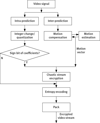
This encryption algorithm is combined with compression algorithm. The basic idea of encoding includes initializing the encoder, creating an encoding instance handle, circular encoding for each frame data, and destroying the existing encoding instance handle to stop encoding. Encryption algorithm is embedded in compressed encoding. For each frame of the image data, the process is shown in Figure 7.18. First, the encoder samples the pixels, and then do DCT. The encryption of the fixed length data is carried out after quantification, and the scrambling of macro-block is done after the entropy encoding. To do so, it will not affect encoding.

According to this procedure, a series of standard test sequences are tested. Figure 7.19 is the encryption effect diagram for two different standard test sequences. Figure 7.19(a) and 7.19(c) is the first frame image of foreman and akiyo, respectively. Figure 7.19(b) is the first frame decoding image of foreman only using the macro-block scrambling method, and Figure 7.19(d) is the first frame decoding image of akiyo using the complete encryption algorithm.
Therefore, attackers cannot get any valuable information from the scrambled and encrypted image. This scheme has good property of format invariance and its control parameters can be further set up to achieve different security levels.
7.4.5Performance Analysis of MPEG Video Encryption System
The performances of encryption system are analyzed mainly from the following two aspects.

Figure 7.19: Video encryption effects: (a) foreman plain image; (b) effect of macro-block scrambling; (c) akiyo plain image; and (d) full encryption effect of this scheme.
7.4.5.1Analysis of the System Security
As discussed previously, for a group of images, key space of the chaotic encryption system consists of {u, v, p, x1(0), y1(0), x2(0)}, which is large enough to resist a brute-force attack. Considering the scrambling process with the size N, for frame p, the majority of macro-blocks come from the corresponding prediction of the previous frame. Because the previous frame has been scrambled, attackers are unable to restore the current image. The same results can be obtained for frame B. For frame I, even in the qicf video clips, the size of scrambling is N = 176 × 144/162 = 99. So the search space is 99! which is large enough to resist the brute-force attack too.
In the fixed length code data encryption, the feedback operation makes secrete key stream to depend on the whole plaintext, and thus can resist the known/chosen plaintext attack. In the scrambling process, if an attacker obtains a pair of plaintext and ciphertext, it is clear that the scrambling table can be obtained by comparing. However, in this system, the scrambling table changes according to the chaotic sequence, and the evolution of chaotic sequence is difficult to be predicted. Therefore, it is not possible to infer the original chaotic sequence from the scrambling algorithm. In addition, the secrete key is changed in real time with the change of images, resulting in that the attack is more difficult.
Experiments show that this algorithm can also resist error concealment attack (ECA). In our experiments, different encryption algorithms are used to encrypt a 176 × 144 akiyo video fragment, and then they are attacked by ECA as shown in

Figure 7.20: Results of ECA attack on the first frame of “akiyo”: (a) encryption algorithm with fixed length data and (b) new algorithm.
Table 7.3: Results of encryption speed test.
| Video clips | Size | Ratio (%) |
| Akiyo | 176 × 144 | 2.5 |
| Carphone | 176 × 144 | 1.9 |
| Foreman | 176 × 144 | 2.1 |
| Miss America | 176 × 144 | 1.6 |
| Dancer | 352 × 288 | 3.1 |
| Singer | 352 × 288 | 2.4 |
Figure 7.20. As can be seen, if a single compressed video stream is encrypted by using fixed length data, a basic outline can be seen after the ECA attack. But it is completely unable to be identified by using our encryption scheme.
7.4.5.2Analysis of Encryption Speed
Experiments show that the new encryption algorithm has a fast speed. By employing two simple chaotic maps and iterating the chaotic maps in the integer domain, the computation time of encryption system is greatly reduced. On the other hand, because of the selected finite fixed length code data to be encrypted and simple scrambling scheme, the average number of iterations is greatly reduced. Taking several 90 frames video fragments as example, the ratios of encryption time and compression time are tested and recorded. Results are shown in Table 7.3. As can be seen, the time cost of encryption process has little effect on the MPEG4 compression, and this scheme can meet the real-time communication requirements.
7.5H.264 Video Encryption Algorithm Based on Chaos
H.264 is a video encoding standard with extremely low bit rate, which is adopted by the International Telecommunication Union. It is the tenth part of MPEG-4 and is also called advanced video coding by the International Organization for Standardization (ISO). H.264 standard has better image quality, higher compression ratio, and better network adaptability than that of the previous video encoding standard. However, its good encoding effect is at the cost of a huge amount of computing. Therefore, the encryption of H.264 should be considered as a simplified encryption algorithm, which can reduce the computational complexity and the cost of secrete key, and simultaneously the compression effect does not be affected.
In this section, a new chaotic video encryption scheme is designed.
7.5.1Chaotic Stream Cipher Based on Tangent Delay-Ellipse Reflecting Cavity System
Chaotic stream cipher is constructed by tangent delay-ellipse reflecting cavity system (TD-ERCS) chaotic system. In fact, the TD-ERCS chaotic system is an iterative map, which is discussed in Section 3.1.4. Iterate the chaotic map for one round at each time, and then the tail numbers of results are extracted to construct pseudorandom binary sequence. The generated sequences x and k are denoted as {xj|j = 1, 2, 3, . . . } and {kj|j = 1, 2, 3, . . .}, where xj and kj represent the iteration values x and k in round m + j – 1. The binary codes of kj and xj mantissa are extracted from low to high and are denoted as ![]() and
and ![]() respectively. The binary pseudorandom sequence s of TD-ERCS is obtained by alternant arranging
respectively. The binary pseudorandom sequence s of TD-ERCS is obtained by alternant arranging ![]() and
and ![]() As it can be seen, when the TD-ERCS goes into normal state, each round of iteration can generate 104-bit binary sequence, which is 13 bytes.
As it can be seen, when the TD-ERCS goes into normal state, each round of iteration can generate 104-bit binary sequence, which is 13 bytes.
According to the characteristics of H.264 standard, the selective encryption algorithm is investigated based on chaotic pseudorandom sequence. The main feature of this algorithm is that chaos is introduced to enhance the security of system and the encryption speed is improved. The encryption algorithm has low complexity and good performance on security and real time. It has little influence on the compression performance of encoding and has certain data operability, which is consistent with the basic requirements of video data encryption.
7.5.2H.264 Video Encryption Scheme
To reduce the amount of data to be encrypted, the most effective data must be selected for encryption. Because the human eye is more sensitive to the brightness information than the color information, and the brightness information and color information are contained in the compressed file separately. Here a few key data are selected to encrypt. The basic encryption framework is shown in Figure 7.21. The encryption content of this scheme includes all sign bits of DC and AC coefficients in 4 × 4 luminance block, the sign bits of DC coefficients in chroma block, and the sign bits in motion vector of P/SP frame and B frame. The reason for choosing these data to encrypt is because those data can maximize the impact of visual effects and maintain the basic compression ratio and signal-to-noise ratio (SNR) of encoding at the minimum cost.
The chaotic stream cipher is designed by using the above pseudorandom sequence s. To improve the security, the following ciphertext feedback mode is adopted. Encryption process is described by
where XOR is the bit XOR operation; s is the secrete key stream; and C(i) is the ciphertext.
Experiments are carried out on the H.264 open-source codec JM. JM is one of the three official encoders of H.264. Although the algorithm is complex and its speed is slow, it is suitable for the second development. To run JM in the VC6.0 compiler, you have to set up configuration file before the coding and decoding. For example, the encoding configuration file can be set to encoder_baseline.cfg.

Figure 7.22: H.264 video encryption effects. (a) First frame of foreman. (b) First frame full encryption of foreman. (c) Encryption symbol bit of brightness of DCT coefficient. (d) Encryption symbol bit of chroma DC coefficient. (e) mv encryption for frame 89 of foreman. (f) Full encryption for frame 89 of foreman. (g) Mobile plain image. (h) Full encryption of mobile image.
In this experiment, the encryption effect of different data in the standard video sequence is recorded as shown in Figure 7.22. As it can be seen, different data can be encrypted to achieve different results. For the encryption of motion vector, an inevitable result is that the encryption effect is not obvious for a set of video sequences at the beginning as shown in Figure 7.22(b). With the accumulation of motions, the ciphertext information of encrypted motion vector will continue to be accumulated, and the effect is more and more obvious as shown in Figure 7.22(e) and 7.22(f). After full encryption, the image has become very blurred as shown in Figure 7.22(f) and 7.22(h). To improve the security of encryption further, we can scramble the frequency coefficient, 4× 4 change block or Flexible Macroblock Ordering (FMO)-based macro-block. Of course, those algorithms are based on the cost of compression ratio and encryption delay.
7.5.3Performance Analysis of Video Encryption
7.5.3.1Security Analysis of the Encryption System
On one hand, for the chaotic pseudorandom sequence generator based on the TD-ERCS map, the total secrete key parameters are (x0, tgα, μ, m), and small changes in parameters will generate a completely different sequence. Obviously, the key space is large enough to resist the brute-force attack. At the same time, because of the real-time variation of the chaotic iteration parameters and initial conditions in each image, the algorithm has the ability to resist the chosen plaintext attack.
On the other hand, for the selective encryption scheme, encrypted data includes the DCT coefficients, which represent the texture information, and the motion vector, which represents the motion information. To do so, the readability of video data can be greatly damaged.
7.5.3.2Real-Time Analysis of the Encryption System
The encryption speed depends on the producing speed of the chaotic stream cipher and the amount of encrypted video data. For TD-ERCS, the system can generate 104-bit secrete key stream for each round of iteration. For encrypted data, the proposed encryption scheme only selects the key data of video stream and only involves the sign bit. For example, considering that the majority of AC coefficients of chroma are zero, the encryption effect is not affected. So the DC coefficients of chroma are chosen to be encrypted. Experiments are carried out on several standard sequences with Quarter Common Intermediate Format (QCIF) format, and the real-time performance is shown in Table 7.4. The percentage of encryption time accounting for encoding time shows that the encryption system has good real-time performance.
Table 7.4: Results of encryption speed.

Any encryption method may have an impact on the encoding effect of video sequences. Practical encryption algorithm should reduce the influence of compression ratio and SNR of video sequences. Because only the sign bits of video data are encrypted, the encryption algorithm has little impact on the SNR and compression ratio of video sequence. This algorithm takes the macro-block, the frame, and the image group as the encoding unit, so it can keep the frame synchronization information of the video data to be invariable, and it has certain data operability, such as supporting the operations of position index, pasting, and cutting. For the encryption to DCT and quantization coefficients, it does not change any information about data format. The experimental results show that the SNR and compression ratio are not affected.
Questions
- What are the technical difficulties of real-time data stream encryption?
- How to evaluate the security of real-time data stream encryption?
- How to deal with the relationship between encryption and compression in video transmission?
- Design a wireless transmission scheme based on chaos.