
7 Drum system
As pioneered in Whirlwind, the AN/FSQ-7 relied on magnetic drums to decouple the operations of the central computer system itself and the variety of asynchronously operating input /output equipment. In addition to this, magnetic drums were used as swap space for programs from core memory –another first of this remarkable machine. Figure 7.1 shows the front view of a frame holding six magnetic drums in the lower half, while the upper half is occupied by the necessary read/write-amplifiers and associated circuitry. All in all twelve magnetic drums were used in an AN/FSQ-7 installation:
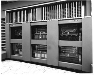
Figure 7.1: Front view of the drum section (courtesy of the Computer History Museum)
LOG: The LOG drum served as interface between the central computer and the long-range radar input (LRI), contained the Output Buffer (OB), and received data from the gap-filler radars (GFI).
MIXD: The MIXD drum was the interface to the manual input system (MI), Intercommunication (IC) (communication with the other AN/FSQ-7 computer in the DC),372 Crosstell (XTL – communication with adjacent DCs and CCs), spare XTL, the Digital Display (DD), and contained one spare auxiliary memory area where program and data could be stored and retrieved by the central computer.
RD and TD: The Radar Display (RD) and Track Data (TD) drums stored radar and track data to be displayed on the various display consoles.
AM: Eight Auxiliary Memory (AM) drums (AM-A, . . . , AM-H) served as storage for program and data.
In contrast to the rather simple auxiliary drum system – being quite similar to other drum systems used for intermediate program and data storage of that time – the LOG, MIXD, RD, and TD drums were much more difficult to interface as they had to decouple the central computer and the asynchronously operating input/output systems. Accordingly, one has to distinguish between so-called Computer-Drum (CD) transfers, where data is transmitted between the central computer and the drum, and Other-than-computer-Drum (OD) transfers, denoting transfers between an input/output unit and a drum, taking place simultaneously.373
Each of the drums is divided into fields 33 bits wide (32 bit data plus one parity bit) with either 2,048 memory locations per field around the circumference of the drum, or 2060 cells in the case of the RD and TD drums. The RD drum has nine such fields (72 kB) while the other eleven drums feature six fields each (48 kB).374
7.1 Magnetic drums
Figure 7.2 shows the layout of a typical magnetic drum used in the AN/FSQ-7. It consists of
- the so-called drum cradle, a hinge allowing the drum assembly to swing out for maintenance,
- shielding cans containing diode switches for the fields accessed through CD-TRANSFERS,
- a 0.5 hp synchronous 3-phase drum motor running at 3600 rpm (this motor, requiring three phases at 208 V had such an excessively high starting current of 125 A that a sequencer was necessary to make sure that only one of these motors was started at a time),
- the drum motor pulley,
- a pulley guard,
- drum belt,
- shielding cans holding diode switches for OD-fields,
- another pulley guard (transparent),
- the drum rotor pulley (due to the transmission ratio of the motor and rotor pulleys, the drum is rotating at 2914 rpm – at this speed the average access time is 10 ms with a maximum of 20 ms, and the transfer time for one 33 bit word is 10 µs),
- a static grounding brush,375 and
- the drum rotor itself.
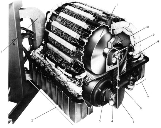
Figure 7.2: Breakdown of mechanical drum assembly (see [IBM DRUM] [p. 7])
The head bars are clearly visible located around the circumference of the drum rotor, each holding 33 read/write heads. These head bars are shifted slightly against each other in horizontal direction, resulting in a one-to-one correspondence of head bars to data fields in the case of an auxiliary drum. The remaining drums, acting as buffers between input/output equipment and the central computer, have corresponding pairs of head bars installed, so each field has two head bars – one connected to the computer and one to the associated input/output device. This arrangement allows parallel read/write transfers for a single field on these buffer drums.
Selecting a drum and a particular field on this drum is implemented by diode switches as shown in figure 7.3: Shown are two drums, A and B, with two fields each (represented by a single head per field). To select a single field, its associated Drum Field Driver (DFD) generates a +125 V signal at its output which is connected to the center tap of all read/write heads belonging to that particular field. All other, unselected DFDs hold their outputs at +70 V. In the picture, the left upper field is selected – since the two diodes at the top left are now in the conducting state, as their anodes are more positive than their cathodes, the two outer connections to the selected head are connected to the plates of the two driver pentodes shown on the lower left while the other heads are deactivated.
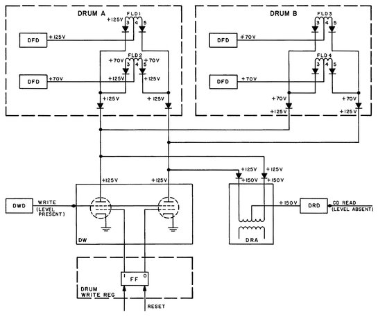
Figure 7.3: Diode switch for drum head selection (see [IBM DRUM] [p. 66])
Since the plate voltage of these two pentodes is supplied by the selected DFD via the selected head and associated diodes, all, what is necessary to write a bit to the drum, is to load the associated flip-flop in the drum write register with the desired value and activate the pentode pair by a positive write level at their suppressor grids. This will tie one end of the read/write head to ground potential while the other will stay at +125 V. Writing a 0 energizes one half of the read/write head while writing a 1 energizes the other half under control of the drum write register.
Reading from the drum works similarly: Each field has an associated Drum Read Driver (DRD) which is connected to the center tap of a decoupling transformer like that shown on the lower right in figure 7.3. An unselected DRD yields +150 V at its output, effectively blocking the two diodes connecting the transformer with the read/write head diode network. When a field is selected for reading, its corresponding DRD output will be at +100 V, so that the two diodes at the transformer will conduct. Accordingly, the secondary of the transformer will show the read-signal from the selected read/write head, feeding a read-amplifier.
Obviously the gap between the read/write heads and the surface of the drum rotor is critical regarding magnetic flux density and thus read/write levels. Figure 7.4 shows the structure of such a read/write head: Its outer aluminum case is tightly screwed to the head bar while the read/write coil with its core and the core gap slides on a carriage within this enclosure. Using the adjustment screw at the top of the head assembly the gap between the lower tip of the actual read/write head and the drum surface can be adjusted.
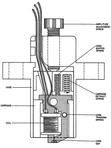
Figure 7.4: Read/write head assembly (see [IBM DRUM] [p. 10])
Since typical run-down and restart times for these drums were of the order of 15 to 20 minutes, some technicians not only adjusted but replaced heads on a running drum as MIKE LOEWEN remembers:
“Some of the maintenance procedures were particularly memorable, such as changing heads on the drums. Because it took in excess of 20 minutes for a drum to spin down, you couldn’t often afford the down time and you changed the head while the drum was turning at speed. It was a nerve wrecking process which involved using an oscilloscope to monitor the signal amplitude on the head. You cranked the head down towards the drum surface until the signal reached the proper level. If the head went too far and actually touched the surface of the drum, it would score the surface and make that track unusable.”376
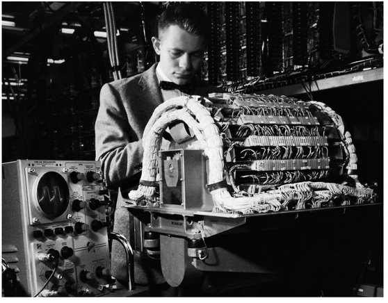
Figure 7.5: Memory drum undergoing maintenance
Figure 7.5 shows a drum undergoing maintenance: A technician adjusts heads for maximum read levels guided by an oscilloscope displaying the current read signal from the particular head under adjustment.
7.2 Timing
The generation of timing signals controlling the actual read/write operations is a central aspect in every rotating storage medium. While modern disk drives normally employ timing and servo information377 which is embedded directly in the data tracks, older systems used a dedicated track for deriving timing information. Basically all drums used in AN/FSQ-7 featured two dedicated tracks holding timing information: One track generated 2048 (or 2060 in the case of the RD and TD drums) pulses per revolution while the other track generated one pulse per revolution yielding the necessary index information denoting the first sector of a track.
The early incarnations of the drums used a glass disk mounted to the drum shaft containing a sinusoidal pattern representing the timing information.378 Timing information was read from this disk by an optical system containing a light source, seven lenses, and a photomultiplier tube with associated amplifiers and logic circuitry to derive proper timing pulses. Since this type of pulse generation would have required a substantial amount of additional hardware per drum,379 the timing information derived by this optical system was written to two tracks on the drum in a preliminary step. Thus a single instance of the signal conditioning hardware, which could be switched from one drum to another, was sufficient to generate timing information and write this onto the two dedicated timing tracks.
This capability of rewriting timing and index information derived by means of this optical system with its associated electronics package was necessary, since erasing a disk, which was sometimes necessary during maintenance, erased all tracks, not just data tracks.380
Later,381 another timing generation method based on an etched timing disk was used, thus rendering the complex optical system with its associated signal generation and shaping electronics obsolete. Figure 7.6 shows such a timing disk with an enlarged section showing the timing and index slots. This disk was mounted on the drum rotor shaft and could be read with a normal read head and associated electronics just like the timing channels written by the OTG in earlier devices. Due to its structure, the etched timing disk was not affected by an erase operation, simplifying operations considerably.
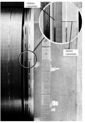
Figure 7.6: Etched timing disk of a drum (see [IBM DRUM][p. 12])
Although data on a drum could simply be overwritten by writing a new bit stream to a particular track, the drums featured a so-called erase bar which allowed all tracks of a drum to be erased at once. This bar was in effect just a single write head as wide as the drum rotor itself. It was powered by a motor controlled Variac during an erase operation. The output of this Variac – driven by a 125 V, 60 Hz signal – was varied slowly from its maximum amplitude to zero. This ensured that the drum did not contain any magnetization patterns at all after an erase operation.382
7.3 Status concept and time stamps
Since all of the drums (with the exception of the auxiliary drums) are used to decouple the asynchronous operations of the central computer and its associated input/output equipment, a synchronization mechanism is necessary.383 Therefore, all input and output fields have two associated status channels of one bit each, the so-called OD and CD status channels. Words of a field containing valid data ready to be read by the computer system are flagged by a 1 bit in their associated CD status channel, while the OD status channel marks fields which have already been read by the computer and can be used by the input equipment to store new incoming data. The CD status channel of an output field tells the computer which words of a field are ready to accept new data while the OD status channel controls the operation of the output system.384
In addition to this embedded and hardware supported status scheme, timing information derived from the clock register being part of the right arithmetic element was inserted automatically into bits L10 to L14 of each GFI data word as it was transferred from the gap filler radars to the GFI field of the LOG drum. This was necessary since all calculations regarding targets and tracks rely primarily on precise time information regarding the input data.
7.4 Data flows
Figure 7.7 shows the overall data flows between the central computer system, the various magnetic drums, and the associated input/output equipment. The central role of the drum system is obvious. Basically, five types of data transfers can be distinguished: 385
- Data source and destination is the central computer, i. e. the drum is used to store programs or data under computer control which is the task of the eight auxiliary drums. These drums do not contain any status channels since they are operated under program control only.
- Data is written to a drum by the input system and read by the computer. Drums used in this mode are the LOG (LRI and GFI fields) and the MIXD drum (MI and XTL fields).
- Data is written to the drum by the computer and read by the output system. This involves the LOG drum (OB fields).
- Data is transferred from the computer to the display system via TD, RD and MIXD drums.
- The active computer transmits data to the standby computer through the MIXD drum (IC field).
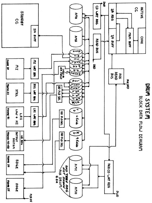
Figure 7.7: Drum system data flow (courtesy of MIKE LOEWEN)