
17. Access Control Panels and Networks
Chapter objectives
1. Get to Know the Basics in the Chapter Overview
2. Learn about Panel Components
3. Learn about Panel Functions
4. Learn about Panel Form Factors
5. Learn about Typical Panel Locations
6. Understand Local and Network Cabling
7. Understand Redundancy and Reliability Factors
8. Answer Questions about Access Control Panels and Networks
CHAPTER OVERVIEW
Access Control Panels perform the heavy lifting in Alarm/Access Control Systems. Every single function that Access Control Systems perform in the real world occurs first in the “mind” of an Access Control Panel.
All Access Control Panels share certain attributes and components. Alarm Input and Output Control Components may be internal or external to the basic Access Control Panel. There are a variety of Access Control Panel Form Factors that can be used in a variety of locations as system needs dictate.
In the past a wide variety of different types of wiring schemes and wiring protocols existed, but today most systems use one or two of only a few. Finally, we will discuss Reliability and Redundancy issues — how to get the most out of the hardware.
Access Control Panels perform the heavy lifting in Alarm/Access Control Systems. Every single function that Access Control Systems perform in the real world occurs first in the “mind” of an Access Control Panel.
All Access Control Panels share certain attributes and components. Alarm Input and Output Control Components may be internal or external to the basic Access Control Panel. There are a variety of Access Control Panel Form Factors that can be used in a variety of Locations as system needs dictate.
In the past a wide variety of different types of wiring schemes and wiring protocols existed, but today most systems use one or two of only a few. Reliability and Redundancy issues and how to get the most out of the hardware are discussed at the end of this chapter.
Keywords: Access Control Panel, Alarm, Input, Mind, Output, Protocol, Redundancy, Reliability, Wiring
Author Information:
Thomas L. Norman, CPP, PSP, CSC, Executive Vice President, Protection Partners International
Access Control Panel Attributes and Components
You will remember that the Second Generation of Access Control Systems was the first to wire all access control devices centrally. The purpose of this was to achieve both centralized control and reporting. Both Second and Third Generation Access Control Systems required that all devices be wired from wherever they were in the building all the way back to the location of the Central Processing Unit (CPU). In the Second Generation this comprised a large object that looked like a giant desk calculator, and in the Third Generation this comprised a mini-computer the size of a four-drawer filing cabinet.
Early Second Generation systems had little if any storage. Their purpose was control, not recordkeeping, of just a very few doors. Third Generation systems operated up to 64 doors. But both Second and Third Generation systems suffered from the same limitation — the number of doors that could be wired back to the CPU. Although this presented a practical limitation in terms of wiring difficulty, it also presented a barrier because of the cost. Even in those times, copper and the labor to run it was expensive. Additionally, the reality of Ohm's Law meant that there was a practical limitation to the distance that doors could be placed away from the CPU.
The whole idea of Fourth Generation Access Control Systems was to find a way to increase the capacity of the systems (numbers of doors connected) and decrease the amount of wiring necessary for each door. I have done budgets that saw as much as 34% of the entire security system budget going to cable and conduit. Although necessary for the operation of the system, cable and conduit contribute nothing to functionality, so anything that can reduce their costs can drive down the overall cost of the entire security system without losing any functionality. Fourth Generation Access Control Systems were the first to “farm out” the access control decisions and operation of remote field devices (locks, etc.) to Access Control Panels instead of connecting all of those devices centrally to a single computer that made all decisions centrally.
The constant theme of security system development has been and continues to be
• More Functions
• Easier to Use
• Lower Cost
With that in mind, let's look at what we have to work with in an Alarm/Access Control System to achieve those goals. An Alarm/Access Control System comprises the following elements:
• Field Elements
• Credential Reader
• Door Lock
• Door Position Switch
• Request-to-Exit Sensor
• Alarm/Access Control System Panels
• Access Control Panels
• Alarm Input Boards
• Output Relay Boards
• Server(s)
• Workstation(s)
• Communications Infrastructure
• Communication Boards (Protocol specific — RS-485, etc.)
• Digital Switches
• Cables and Conduits
• Software
• Operating Systems
• Software
Of all these, the best places to achieve our three goals are
• More Functions — System Software and Hardware Interfaces
• Easier to Use — System Software
• Lower Cost
• System Architecture (Alarm/Access Control System Panels)
• Anything to reduce the need for Cables (Panel Design)
• We can also expect the cost of Servers and Workstations to continue to decline
We look at Access Control Panel Form Factors next in this chapter, and you will see how panel design can dramatically affect cable and conduit costs.
So back to Access Control Panels. Let's look at how their components and attributes contribute to their functions. Once this is understood, we can begin manipulating them to do more at lower costs.
Let's call the term “Access Control Panel,” a generic phrase that can include:
• An electronics panel that can interface with and control Access Control System Field Devices (credential reader, electrified lock, door position switch, and request-to-exit devices)
• An electronics panel that can interface with alarm devices (alarm input board)
• An electronics panel that can control electrical devices (output control panel)
The panel must communicate with the Access Control System. It must be able to make access control decisions locally based on information stored about the user presenting his/her credential and then after operating the access portal, and it must report the event to the master Access Control System database archive.
So the Alarm/Access Control System Panel includes all the elements shown in Figure 17-1.
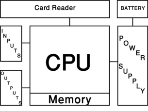
Communications Board
The Communications Board provides the communications to and from the System Server(s). It is wired to the servers using a digital protocol. The most common digital protocols used to connect Access Control Panels to their Servers include:
• Ethernet (TCP/IP)
• RS-485 (4-Wire)
• RS-485 (2-Wire)
• RS-232
• Protocol B (Older Cardkey Protocol)
In addition to allowing communications with the Server(s), the Communications Board may also allow downstream communications to other Access Control Panels and/or a local connection to a diagnostic laptop computer. It is common to see one Access Control Panel that connects using TCP/IP that connects to the Server and then that same panel connects to a number of other access control panels using RS-485. This reduces demands on digital switches and extends the distance over which communications can take place.
There are several different types of Cabling and Networking used in the security industry. These are discussed later in this chapter (Local and Network Cabling).
Power Supply and Battery
Each Access Control Panel is equipped with a low-voltage Power Supply that converts Mains AC Power to Low Voltage DC power. Access Control Panels are often also equipped with a back-up battery to ensure consistent power in case of a sudden voltage drop or other disturbance. The battery should be sufficient to power the panel and its locks for up to four hours.
Central Processing Unit
The CPU is the “brain” of the Access Control Panel. This device performs the following functions:
• Receives downloaded data from Server(s)
• Time Zones
• Portal Configurations
• Database of Authorized Users for Portals under the control of the Access Control Panel including:
- Users
- Portals Authorized
- Time Zones Authorized
• Makes Access Control Decisions
• Receives request from the Credential Reader
• Queries the on-board memory for the authorization for this user for that access portal
• Makes the access control decision (Grant/Deny)
• If the decision is to grant access:
- Unlocks the door
- Suppresses the door alarm
- Re-locks the door on closure
- Resets the door alarm on door closure
• Receives alarm status information from the Alarm Inputs
• Directs the Output Control to activate a relay
• Communicates all event data to the on-board memory (first in-first out)
• Communicates all event data to the Server(s)
Erasable Programmable Read-Only Memory
The Erasable Programmable Read-Only Memory (EPROM) is a data circuit that retains its memory even when power is off. Security System Manufacturers use EPROMs to hold both the Operating System and the Program for the Access Control Panel. The CPU performs the logical functions, but it gets its instructions from the EPROM.
The difference between Fourth and Fifth Generation Access Control Systems is the extent to which the EPROM determines what functions are performed and how they are performed. Fourth Generation Systems get all their instructions from EPROMs. whereas Fifth Generation Systems get some of their instructions from EPROMS and the balance of their instructions from the contents of Structured Query Language (SQL) databases (or their equivalent in another language than SQL).
This is an important distinction because Fourth Generation Systems can perform ONLY the functions described by the EPROM, but Fifth Generations Systems can perform virtually any function based upon the contents of the SQL database, plus the status of inputs and outputs, counters, and timers. Thus, virtually any imaginable function can be performed by a Fifth Generation Access Control System.
Random Access Memory
The Access Control Panel needs Random Access Memory (RAM) to store its decision resource information (time zones, access levels, user information, etc.) and its event history. In early Fourth Generation Access Control Systems, this memory was limited due to cost. Today it is common to see systems that sport comparatively enormous memory.
The larger memory of Fifth Generation Systems allows for SQL functions that earlier systems were incapable of performing, making those very capable machines.
Input/Output Interfaces
As capable as all of the previously mentioned components are, they are of no use if they cannot connect to devices in the real world. Most Access Control Panels have the following Input/Output connections:
• Between 1 to 16 Credential Reader Inputs
• Between 1 to 16 Door Position Switch Inputs
• Between 1 to 16 Door Lock Control Relays
• Between 1 to 16 Request-to-Exit Sensors
• Between zero to 8 Alarm Input Points
• Between zero to 8 Output Relay Points
Increasingly, Inputs and Outputs of all kinds are relegated off the Main Access Control Panel electronics “Motherboard” and onto so-called “Daughter” boards. Often the only difference between an Access Control Panel that can control 2 readers and one that can control 16 is the connectors on the Motherboard and the programming of its EPROM.
Additionally, there is a trend toward software rather than hardware interfaces to other systems. Long ago if one wanted to integrate an access control system to a video or intercom system, for example, to trigger a camera in response to an alarm, it was always done by connecting a relay dry contact from the access control system to an input on the video system, or by connecting a dry contact on an intercom call button to an alarm input on the access control system. Today, this kind of interface is mostly accomplished by a software interface using a “Software Developers Kit” (SDK). Accordingly, several manufacturers have discontinued older “multi-connection” Input and Output boards in favor of smaller 8 input or output boards. At this time, there is a healthy black market for the older 32- and 48 point boards, which were far more economical.
Access control manufacturers are always looking for new ways to make a buck and as software is replacing hardware, some are relying on making the rarer hardware interfaces more costly.
Regardless, hardware interfaces have their benefits. The foremost problem with interfacing two systems from different manufacturers using software is that the interface is only as good as the latest software version from both manufacturers. There have been cases where software has been integrated in one version only to be abandoned in later versions, forever compelling the owners of the earlier version to hold onto their now outdated software versions or else lose the integration. Hardware interfaces do not have this problem. As long as the new software version still talks to the old hardware, you are golden. Manufacturers tend to support their own older hardware much longer than the software interfaces of other manufacturers.
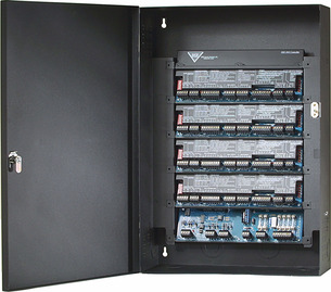
Access Control Panel Form Factors
The architecture of the basic panel shown in the previous section can take many forms (Figure 17.2). The most common include:
• 2, 4, 8, or 16 door connections
• Additional inputs and outputs on the Main Access Control Panel
• Input and Output Boards moved off the main Access Control Panel board as separate boards attaching to the Access Control Panel or directly on the Communications path
If we remember that our goal is to increase functionality, ease of use, and reduce costs, how then can system Access Control Panel Form Factors contribute to these goals?
Let's look at each goal:
• Increase Functionality: This derives from the design of the CPU, the amount of memory available, and the functions defined by the EPROM.
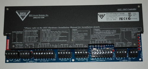
• Improve User Experience: Sorry, this is almost entirely a software function. However, there are a couple of brands of Access Control Systems that label their Access Control Panels so well that as-built documentation is virtually unnecessary in the field (Figure 17.3). Those are a pleasure for installers and maintenance technicians to work with. (Thanks DSX!)
• Reduce Costs: Here is where system architecture can make a very large difference.
Virtually unlimited functionality can be achieved by allowing the integrator to access the status and function of every single access control system attribute through SQL commands and data fields.
The Access Control Industry is still in the “toddler” phase of Fifth Generation Technology. A surprising number of Access Control System manufacturers have no idea what their Access Control Systems are capable of when properly programmed. Quite understandably, these are the manufacturers that limit what system attributes and functions their SQL programming can access, and generally these systems also make it complicated to access their SQL programming at all.
This will all change as smart manufacturers begin to see profits from allowing their system integrators and end users to access the full capabilities of their systems. This process may take a decade.
When I wrote Integrated Security Systems Design in 2006, I predicted that a new type of Access Control Panel would be introduced into the market. I called it a “Microcontroller.” I described a tiny Access Control Panel that could fit into an electrical box above a door, designed to control just one door. I indicated that Microcontrollers would be connected via TCP/IP to their Servers. When I first introduced this idea, I was universally declared an idiot. Today, most major manufacturers have Microcontrollers in their product line.
The Microcontroller has not fully matured. I predicted that the Microcontrollers would not only operate a single door, but would also include a couple of alarm inputs and output control relays, and most important, include a 4-port 100Base-T Digital Switch that provided 2 ports for local devices (camera and intercom) and one each of uplink/downlink ports. Several Microcontrollers include the alarm input and output control points, but none so far includes the digital switch. This will eventually change, because the market wants it.
Access Control Panel Functions
Access Control Panels have a number of basic functions that we have come to expect from anything defined as an Access Control Panel; however, they can also provide many more functions.
Every Access Control Panel must do the following to be an Access Control Panel:
• Receive downloaded data from Server(s)
• Time Zones
• Portal Configurations
- Credential Reader Type/Time Zone for Operation
- Lock Type, unlock time, re-lock function, etc.
- Door Position Switch (Normally Open/Normally Closed)
- Request-to-Exit Sensor (Normally Open/Normally Closed)
- Portal Operation Time Zone (otherwise unlocked or locked without any access possible)
• Database of Authorized Users for Portals under the control of the Access Control Panel
- List of Authorized Users (their credential number)
- Portals Authorized on this Access Control Panel
- Time Zones Authorized for Each User on Each Portal on this Access Control Panel
• Make Access Control Decisions
• Receive request from the Credential Reader
• Query the on-board memory for the authorization for this user for that access portal
• Make the access control decision (Grant/Deny)
• If the decision is to grant access:
- Unlock the door
- Suppress the door alarm
- Re-lock the door on closure
- Reset the door alarm on door closure
• Receive alarm status information from the Alarm Inputs
• Direct the Output Control to activate a relay
• Communicate all event data to the on-board memory (first in-first out)
• Communicate all event data to the Server(s)
Many Access Control Panels also do the following:
• Communicate with other Access Control Panels
• Communicate with outboard Alarm Input Boards
• Communicate with outboard Output Relay Boards
• Interlink with other Access Control Panels to create a Global Anti-passback function
Fifth Generation Access Control Panels can also:
• Allow access to all system functions and attributes through SQL or similar language
True, fully developed Fifth Generation Systems will exist in both the physical and virtual world. That is, for every device or attribute in the physical world (card reader, alarm input, output control, etc.) there will be an equivalent device in software that allows access to and from the physical device. Each device has attributes that can be accessed for status (open/closed, secure, alarm, bypass and trouble, card reader digital data stream, etc.), and each device has functions that can be executed (unlock, sound buzzer, light a lamp, etc.). In addition to all the devices in the physical world, the Access Control Panel also has purely logical devices such as counters, timers and clocks.
Fully developed Fifth Generation Systems blur the line between physical and logical worlds. Every alarm exists in both worlds and every output control exists in both worlds, so one can have both a physical alarm display on a Workstation Map and create a virtual alarm that can cause events to actuate, counters, timers and in logical combinations with other system device's status can execute very complicated logical actions. For example, on the first valid card read at the parking structure vehicle entry of a corporate building in the morning, the system will:
• Store a video image of the driver, the car, and the license plate in the Access Control System database along with the card reading event
• Set an Anti-passback Event to prevent an Authorized User from passing back his/her card to the next driver in line who is unauthorized to enter the Employee Parking Area
• Set the Employee Door to Unlock on reading the same Authorized User's Credential
• Turn on Building Core Lighting
• Turn off Building Signage Lighting (if also daylight)
• If a Working Day:
• Turn on Building HVAC
• Turn on power to Vending Machines in Employee Lounges
• Change PABX Answering Message from Night to Working Day Message
• If a Weekend Day or Holiday:
• Turn on power to Vending Machines in Employee Lounge nearest to this Authorized User's work area
• Turn on HVAC Zone for this Authorized User's work area
• If Night:
• Turn on path lights from Parking Structure to work area for this particular Authorized User
• Turn on HVAC Zone for this Authorized User's work area
• Turn on power to Vending Machines in Employee Lounge nearest to this Authorized User's work area
• If same Authorized User leaves the Parking Structure:
• Scan database to see if any other authorized users remain in the building
• If no other Authorized Users during Night, Weekend, or Holiday Day:
- Sweep off HVAC
- Sweep off power to all vending machines
• If other Authorized Users still in the building:
- Turn off HVAC for unused zones
- Turn off Vending Machine Power to unused zones
• Close out the Anti-passback Event
In other words, virtually anything you can imagine, the system can do. Although Fifth Generation Systems can possess truly awesome power, few do today because few manufacturers provide access to the full complement of system devices, attributes, and functions. This too will change.
Access Control Panel Locations
Remembering that one of the key goals of Access Control System design is to minimize the cost of system installations, it is worthwhile to note that where you locate Access Control System Panels greatly affects overall system cost.
Imagine for a moment that we have an Access Control System in a ten-story building with 100 access controlled doors and that all of the Access Control Panels are located in the same room with the Server.
As you can imagine, the cost for cabling from Access Control Panels to servers would be tiny, while the cost for cabling and conduit from Access Control Panels to all 100 doors spread across a ten-story building would likely dwarf the cost of the Access Control System. The decision on placement of Access Control System Panels has cost consequences.
As Access Control Systems moved from older proprietary wiring schemes to TCP/IP Ethernet communication, this has opened up new opportunities for cost savings (more on this in the next section).
Generally, conventional old-style Access Control Panels should be located in a secure location such as a Telecom Room. The room should have a locked door, and I recommend that it also have a Card Reader and Door Position Switch on the door. I often design Access Control Panels into rooms that include a camera facing the door with video motion detection to confirm the door opening. Access Control Panels should be located as near as possible to the doors they serve to minimize cable and conduit costs.
Each Access Control Panel should be accompanied by a Lock Power Supply. These must all be served by reliable power, preferably power from an Uninterruptable Power Supply (UPS) that is backed up by an Emergency Generator. The Access Control Panel should also be equipped with four-hour battery back-up. All panels should be key-locked and equipped with a tamper switch.
There is a fine balance between reducing the number of Credential Reader inputs to minimize cabling and conduit costs, and understanding that Access Control Panels that can accommodate fewer readers often cost more than those with a higher reader capacity. I suggest that a per foot (or meter) panel to portal cable/conduit cost should be calculated and then costs should be estimated for cabling and conduit based on maximum reader density panels, centrally located on each floor (or section) of a building. Then look to see if the additional cost of lower reader density panels is outweighed by the lower cost of cable and conduit if Access Control Panels are distributed throughout the floor.
When distributed, security of the panels and Lock Power Supplies may be maintained by placing the panels above the ceiling, accessible through removable ceiling tiles or ceiling access panels. Wherever the panels are located, they should always be located on the “secure” side of the wall, behind an access-controlled door, and never above the ceiling in a public or semi-public hallway.
Microcontrollers with integral digital switches offer the maximum potential cost reduction as they become commodities. With a typical Microcontroller located in a junction box (j-box) just above the controlled door, Microcontrollers provide the minimum possible wiring to each door.
Adding to that a digital switch–equipped Microcontroller also reduces wiring costs for a nearby digital camera and digital intercom. The wiring to a Microcontroller then becomes only two wires (Ethernet and Power), with the added possibility for Power over Ethernet (PoE), depending on the configuration. Microcontrollers should always be placed in a j-box over the secure side of the door, never on the unsecure side.
Note: One manufacturer, who I otherwise respect highly, makes a Microcontroller that has an integrated card reader, thus placing the Microcontroller in a j-box at waist height on the unsecure side of the door. These should be used with extreme caution as one can remove the card reader and have immediate access to lock power, and thus the ability to enter the door from the unsecure side with only hand-tools. It goes without saying that these should never, under any circumstances, be used on exterior doors.
Local and Network Cabling
In the early days of Access Control Systems, each manufacturer used its own wiring scheme, its own operating system, and its own communications protocol. This provided excellent security, since a “hacker” could not easily break into the system, but upon doing so, he would find data that he could not understand. This was especially true for those higher echelon systems that encrypted their data. However, this also made for completely proprietary systems that were impossible to interface with other security systems except by using alarm inputs, dry contacts, and RS-232 connections between computers of different systems.
Gradually, the security industry gravitated toward more universal communications protocols in an effort to minimize development and manufacturing costs. The most common communications protocols for Access Control Systems became:
• RS-232
• RS-485 (2- or 4-Wire)
• RS-422
• And finally, TCP/IP
RS-232 (Recommended Standard 232): This is the name for a series of serial binary single-ended data and control system signals connecting between Data Terminal Equipment (DTE) and Data Circuit-Terminating Equipment (DCE). Until recently it was the most common wiring scheme for computer serial ports (replaced by Universal Serial Bus, USB). It is still used extensively to communicate between Access Control Panels and a local diagnostic laptop computer, and sometimes it is still used to communicate to a system server, although this has been mostly replaced by TCP/IP Ethernet connections.
RS-485 (also known as TIA/EIA-485): This is a standard that defines the electrical characteristics of drivers and receivers used in balanced digital systems. It is capable of point-to-point or point-to-multipoint wiring configurations. RS-485 is especially attractive because it can support communications across long distances as compared to Lantronics, RS-232, and Ethernet. The RS-485 standard only specifies the electrical characteristics of the transmitter and receiver. It does not specify the digital communications protocol. This factor made it highly attractive to access control system manufacturers who wanted to maintain their own proprietary communications protocols. RS-485 offers data transmission speeds of between 100 Kb/second at 1,200 m and up to 35 Mb/second up to 10 m. Because it uses a differential balanced line over twisted pair copper, it can easily communicate over long distances up to 4,000 feet, or just over 1,200 m. RS-485 can operate as half-duplex (talk or listen but not both at the same time) over 2 wires and can be configured for full-duplex operation (talk and listen simultaneously) over 4 wires. RS-485 can operate as point-to-point (between two devices) or as multipoint (daisy-chaining several devices along a single RS-485 line). RS-422 can be configured to operate in a star-communications fashion by using a repeater (star coupler), which isolates each leg of communications from the others.
RS-422 (also known as ANSI/TIA/EIA-422-B): This is an ANSI standard. RS-422 can operate as point-to-point or multi-drop, whereas RS-485 operates as multipoint. Unlike RS-485, RS-422 does not allow for multiple transmitters, only multiple receivers. RS-422 allows for higher data rates than RS-485, but its architecture characteristics have limited its acceptance as a primary wiring protocol in access control systems. Like RS-485, RS-422 does not specify a communications protocol, allowing manufacturers to use their own proprietary protocols. RS-422 is often used as an RS-232 extender.
Ethernet TCP/IP: Today, most Access Control Panels communicate to their Server(s) using Ethernet (TCP/IP). This is good for a number of reasons, but chiefly for standardization. The speed with which the security industry has adopted Ethernet connectivity is purely a result of customer demand. As companies moved toward “Enterprise” systems (systems that span across facilities, campuses, cities, states, and even country borders), all other communications systems except for Ethernet are unable to do this.
TCP/IP is an industry standard for both the Information Technology Industry and for the Security Industry. This also means that an access control system that communicates using Ethernet TCP/IP also uses a common operating system and can “talk” with other systems using the same operating system, such as Microsoft Windows. This also opened up Access Control Panels to communicate using the same protocol as the Server and Workstations, and of course other related systems like Digital Video and Digital Intercom systems. Finally, all of these systems can speak the same language (usually SQL), enabling functionality and interfacing options on a scale never before possible.
Ethernet systems link together across digital switches and routers. Although all Ethernet enabled Access Control Systems communicate using TCP/IP, it is only one of several protocols available on Ethernet.
All TCP/IP systems ensure that each packet is received (it re-transmits the same packet as many times as necessary until its receipt is acknowledged). But TCP/IP protocol is a bad idea for Digital Video and Intercom systems. If we lose a pixel in a picture, we do not want to see it inserted into the next frame. Using TCP/IP protocol on audio also results in “grainy” static-filled audio that can become unintelligible.
For those technologies, UDP/IP and RTP/IP are protocols that do not try to re-send lost packets. These are called “streaming” protocols because the receiving device receives an uninterrupted stream of data from the sender. TCP/IP is also well adapted to Unicast protocol, which is point-to-point in nature (one transmitter and one receiver). In Unicast protocol, there is one data stream for each receiving device. If a transmitting device needs to send to four receiving devices, it will send four individual data streams.
For Digital Video and Intercom systems, where there is a need to send to multiple receiving devices, Multicast Protocol can be used. This is Point-to-Multipoint communication (One-to-Many).
Multicast Protocol should not be used on a switch port serving TCP/IP devices, as it will cause communications problems. Accordingly, it is important to establish a “Virtual Local Area Network (VLAN)” on the digital switch network to isolate TCP/IP devices such as Access Control Panels from UDP/IP or RTP/IP devices such as Digital Video or Digital Intercom systems. A typical VLAN configuration is as follows:
VLAN 0 — Not used
VLAN 1 — Administrative VLAN for Digital Switches
VLAN 2 — Digital Video VLAN
VLAN 3 — Alarm/Access Control System VLAN
VLAN 4 — Digital Intercom VLAN
VLAN 2 — Addressing Scheme
• 10.128.2.XXX
• 10.128.2.10 — Beginning Address for Digital Video Servers
• 10.128.2.50 — Beginning Address for Digital Video Workstations
• 10.128.2.100 — Beginning Address for Digital Video Cameras and Encoders
VLAN 3 — Addressing Scheme
• 10.128.3.XXX
• 10.128.3.10 — Beginning Address for Alarm/Access Control System Servers
• 10.128.3.50 — Beginning Address for Alarm/Access Control System Workstations
• 10.128.3.100 — Beginning Address for Alarm/Access Control System Panels
VLAN 4 — Addressing Scheme
• 10.128.4.XXX
• 10.128.4.10 — Address for Digital Intercom Matrix Switch
Each port on each digital switch must be configured for the correct protocol as well (TCP/IP, UDP/IP, or RTP/IP) and Unicast and/or Multicast enabled. Do not mix TCP/IP and UDP/RTP on the same port. Unicast and Multicast can both be enabled on UDP/RTP ports, but Multicast cannot be enabled on TCP/IP ports.
Redundancy and Reliability Factors
Many Access Control Systems are “Mission Critical Systems”; that is, the operation of the Access Control System is critical to the mission of the organization. Accordingly, reliability is a primary factor in the design and maintenance of Access Control Systems. The key to reliability is good design, good installation, good wiring, good power, and a good data infrastructure.
Good Wiring and Installation
I am occasionally asked to visit an existing Access Control System installation that is not working properly. Invariably, I am consistently stunned at poor wiring practices when I tour these installations. Good wiring practices do more than look good, they help ensure reliable system operation.
Good Design
What makes a good design, and why is it so important? A good design is one that ensures that the system will be reliable, expandable, and flexible. Reliable design includes enclosing all exposed system cables in conduit and ensuring that power is reliable (see the section Good Power).
System panels must be in secured locations that are environmentally appropriate (no Janitor's Closets). The environment should ideally be temperature and humidity controlled to within the rated temperature and humidity operating range of the Access Control Panel. The closer that is to the extremes, the less ideal it is. The temperature should be largely within the middle of the range, so it is best not to mount Access Control Panels outdoors in very hot or cold climates. Although an environment with air conditioning would be ideal, it is not always necessary if the area generally maintains a stable temperature and humidity.
Be careful to select an access control system that provides extensive expansion capabilities, well beyond the logical immediate needs of the Owner. Many systems have been replaced due to unforeseen expansion of a system into an Enterprise class system when it was found that the original system could not communicate across a TCP/IP network.
Similarly, the system should have capabilities far beyond those needed immediately. This ensures that no matter what needs develop, the system can accommodate them.
Good Power
After poor wiring, power quality and reliability are probably the biggest problems with unreliable Alarm/Access Control Systems. On too many systems, designers and installers assume that “power is the owner's responsibility.” I routinely see Access Control Panel A/C power plugs simply plugged into a convenient nearby power receptacle from who knows what source. Oh yeah, and that plug is in fact plugged into a three-way tap on the top half of the receptacle, and there is another one on the lower half of the receptacle that is serving a nearby window air conditioner, a small refrigerator, and a small electrical heater. This is a formula for a highly unreliable Access Control System.
Alarm/Access Control System power should be provided from a dedicated clean power source, on its own circuit breaker, and not on a circuit with any “noise-producing” equipment such as air conditioners, refrigerators, heaters, or fan units.
Power for the Security System should be backed up by a UPS (one for the whole system per building) and that should be backed up by an Emergency Generator.
Each Access Control Panel should be equipped with a four-hour back-up battery, which should be sufficient to power the panel and locks for four hours.
Good Data Infrastructure
For systems that communicate using TCP/IP, this is often also equally overlooked. Reliable digital communications require quality digital switches. I strongly advise you not to skimp on switches. Digital switches should be a major brand of commercial grade switch such as Cisco, 3Com, HP, or similar. Use “computer store brand” switches at your peril. There is a vast difference in capabilities between a $2,000 switch and a $20 switch.
Especially important is to never under any circumstances use a Hub instead of a Switch in an Alarm/Access Control System network. Although the security system may not include a digital video system in the beginning, that element could be added later on and when there is a “BANG,” your system will go down! Hubs are completely incompatible with Digital Video Multicast Protocol (Internet Group Management Protocol, IGMP). The use of a Hub in a digital system that includes any IGMP devices such as digital video cameras or encoders will cause the entire system to stop communicating. This is because the TCP/IP devices see the multicast signals on their Hub port and attempt to answer the IGMP group membership request. Repeatedly! Again and Again! Eventually resulting in what is effectively a Denial of Service (DoS) attack from within the system, effectively bringing the entire system to its knees until there is no effective communications. Don't use Hubs at all and you will be safe from this issue.
As part of a mission critical system, the switch should have a redundant power supply and lots of buffering, and it should be remotely configurable across the network. The switch should be capable of supporting multiple VLANs, Virtual Private Networks (VPNs), and protocols (TCP/IP, UDP/IP, RTP/IP, Unicast, and Multicast to each individual port). I strongly recommend that you do not mix brands of switches on the same network. This leads to configuration complications and reliability problems. Except for switches in the same physical room, digital switches should uplink via Fiber to avoid data interference.
Redundancy
Everything fails. And redundancy helps ensure reliability when things fail. The following items should be configured with redundant systems or devices:
• A/C Power:
• Provide power from two sources to each server and digital switch
• Provide power to the whole system from a UPS
• Back up the UPS with an Emergency Generator
• Back up Access Control Panel Power with four-hour back-up batteries
• Digital Communications:
• Configure the Uplink/Downlink on digital switches as a fiber-optic loop such that if communication is lost between any two digital switches, data can flow in the opposite direction around the loop
• Servers:
• Use a redundant mirrored fail-over server (operates continuously mirroring the primary server and takes over if the primary server fails)
• At a minimum, use a fail-over server (takes over only if the primary server fails)
• Heartbeat and Watchdog Timer:
• Configure the digital communications system with a heartbeat and a watchdog timer to ensure continuous communications (the heartbeat is checked constantly by the watchdog to ensure that the digital infrastructure is communicating and the Watchdog timer resets digital switches if communications fail and notifies the operator of the reset (event and success/failure). This requires digital infrastructure monitoring software.
Chapter Summary
1. The constant theme of security system development has been and continues to be
• More Functions
• Easier to Use
• Lower Cost
2. Fourth Generation Access Control Systems were the first to “farm out” the access control decisions and operation of remote field devices (locks, etc.) to Access Control Panels instead of connecting all those devices centrally to a single computer that made all decisions centrally.
3. Access Control Panel is a generic phrase that can include:
• An electronics panel that can interface with and control Access Control System Field Devices (credential reader, electrified lock, door position switch, and request-to-exit devices)
• An electronics panel that can interface with alarm devices (alarm input board)
• An electronics panel that can control electrical devices (output control panel)
4. Basic Access Control Panel components include:
• A communications board
• A power supply and battery
• A Central Processing Unit (CPU)
• An EPROM
• Random Access Memory (RAM)
• Input/Output Interfaces
5. Access Control Panel form factors include:
• 2, 4, 8, or 16 door connections
• Additional inputs and outputs on the Main Access Control Panel
• Input and Output Boards moved off the main Access Control Panel board as separate boards attaching to the Access Control Panel or directly on the Communications path
6. Access Control Panel functions include:
• Receiving downloaded data from the server(s)
• Making access control decisions
• Receiving alarm status information from the alarm inputs
• Directing the output control to activate a relay
• Communicating all event data to the on-board memory (first in-first out)
• Communicating all event data to the Server(s)
7. Many Access Control Panels also do the following:
• Communicate with other Access Control Panels
• Communicate with outboard Alarm Input Boards
• Communicate with outboard Output Relay Boards
• Interlink with other Access Control Panels to create a Global Anti-passback function
8. Fifth Generation Access Control Panels can also:
• Allow access to all system functions and attributes through SQL or similar language
9. Access Control Panel location selection has a very big effect on cabling costs
10. Common local and network connection communication protocols for access control systems include:
• RS-232
• RS-485 (2- or 4-Wire)
• RS-422
• TCP/IP
11. Multicast Protocol should not be used on a switch port serving TCP/IP devices as it will cause communications problems.
12. A typical VLAN configuration is as follows:
• VLAN 0 — Not used
• VLAN 1 — Administrative VLAN for Digital Switches
• VLAN 2 — Digital Video VLAN
• VLAN 3 — Alarm/Access Control System VLAN
• VLAN 4 — Digital Intercom VLAN
13. The key to reliability is good design, good installation, good wiring, good power, and a good data infrastructure.
14. Good wiring practices do more than look good; they help ensure reliable system operation.
15. A good design is one that ensures that the system will be reliable, expandable, and flexible.
16. Reliable design includes enclosing all exposed system cables in conduit and ensuring that power is reliable.
17. After poor wiring, power quality and reliability are probably the biggest problems with unreliable Alarm/Access Control Systems.
18. Reliable digital communications requires quality digital switches.
19. Everything fails. Redundancy helps ensure reliability when things fail.
1) The purpose of wiring all access control devices centrally was to
a. Achieve both centralized control and reporting
b. Achieve both centralized command and control
c. Achieve both centralized management and distribution
d. Achieve both centralized delivery and maintenance
2) The constant theme of security system development has been and continues to be
a. More Functions
b. Easier to Use
c. Lower Cost
d. All of the above
3) An Alarm/Access Control System comprises
a. Field Elements and System Panels
b. Servers and Workstations
c. Communications Infrastructure and Software
d. All of the above
4) An Access Control Panel must communicate with the
a. Digital Video System
b. Access Control System
c. Security Intercom System
d. Building Automation System
5) The Access Control Panel must make
a. Access Control decisions
b. Alarm decisions
c. Employee plan decisions
d. Visitor plan decisions
6) Access Control Panels include
a. A Communications Board and EPROM
b. A Power Supply and Random Access Memory (RAM)
c. A Central Processing Unit and Input/Output Interfaces
d. All of the above
7) Access Control Panel Functions must
a. Receive downloaded data from servers
b. Make Access Control decisions
c. Receive alarm status information from alarm inputs
d. All of the above
8) Access Control Panel Functions must
a. Direct the Output Control to activate a relay
b. Communicate all event data to the on-board memory
c. Communicate all event data to the server(s)
d. All of the above
9) Access Control Panel Functions must
a. Direct the Output Control to turn on the workstation
b. Communicate all event data to the Building Automation System
c. Both a and b
d. Neither a nor b
10) Access Control Panel Functions may
a. Communicate with other Access Control Panels
b. Communicate with outboard Alarm Input Panels
c. Both a and b
d. Neither a nor b
11) Access Control Panel Functions may
a. Interlink with other Access Control Panels to create a Global Anti-passback function
b. Communicate with outboard Output Relay Panels
c. Both a and b
d. Neither a nor b
12) Access Control Panel Functions may
a. Interlink with the CCTV system to monitor intercoms
b. Interlink with the Intercom system to monitor fire alarms
c. Both a and b
d. Neither a nor b
13) Fifth Generation Access Control Panels can also:
a. Allow access to all system functions and attributes through SQL or similar language
b. Allow access to all system functions and attributes through Pascal, Fortran, or similar language
c. Allow access to all CCTV system functions and attributes through dry contact interfaces
d. None of the above
14) Fully developed Fifth Generation Systems
a. Blur the line between physical and logical worlds
b. Blur the line between Alarm and CCTV Systems
c. Blur the line between operators and guards
d. None of the above
15) TCP/IP Ethernet communication
a. Has made Alarm/Access Control Systems more costly
b. Has opened up new opportunities for cost savings
c. Has allowed PC Computers to operate card readers through USB connections
d. None of the above
16) The most common communications protocols for Access Control systems included
a. RS-232, RS485, RS-422, and TCP/IP
b. RS-232 and RS485
c. RS-422 and TCP/IP
d. None of the above
17) Because of ___________ it is important to establish a VLAN on the digital switch network to isolate devices' Access Control Panels from Digital Video or Intercom Systems.
a. Unicast Protocol
b. Multicast Protocol
c. UUNet Protocol
d. International Protocol
18) Redundancy helps assure reliability when
a. Earthquakes strike
b. Tsunamis strike
c. Employees strike
d. Things fail
Answers: 1) a, 2) d, 3) d, 4) b, 5) a, 6) d, 7) d, 8) d, 9) d, 10) c, 11) c, 12) d, 13) a, 14) a, 15) b, 16) a, 17) b, 18) d
..................Content has been hidden....................
You can't read the all page of ebook, please click here login for view all page.