
CHAPTER 15
Real-Time Interfacing with the PRU-ICSS
The Beagle board AM335x SoC contains two programmable real-time units (PRUs) that can be used for certain real-time operations, and these are the focus of this chapter. The chapter begins with input and output examples that help explain the operation of the PRUs and their encompassing industrial communication subsystem (PRU-ICSS). The real-time capabilities of the AM335x are demonstrated using two applications—the first generates custom waveforms on a GPIO, and the second uses a low-cost ultrasonic distance sensor that requires precise timing to communicate the distance to an obstacle.
EQUIPMENT REQUIRED FOR THIS CHAPTER:
- Any Beagle board
- LED, FET (e.g., BS270), push button, capacitors, and resistors
- Oscilloscope (optional but useful)
- HC-SR04 ultrasonic sensor and logic-level translator board
Further resources for this chapter are available at www.exploringbeaglebone.com/chapter15/.
The PRU-ICSS
The Programmable Real-Time Unit and Industrial Communication Subsystem (PRU-ICSS) on the Beagle board's AM335x SoC contains two 32-bit 200 MHz RISC cores, called PRUs. These PRUs have their own local memory allocation, but they can also use the BeagleBone P8/P9 or PocketBeagle P1/P2 header pins and share memory with the Linux host device.
The PRU-ICSS is a valuable addition to a general embedded Linux platform, as it can provide support for interfacing applications that have hard real-time constraints. It is important to note that the PRU-ICSS is not a hardware accelerator—it cannot be used to improve the general performance of code that is executing on the Linux host device. Rather, it can be used to manipulate inputs, outputs, and memory-mapped data structures to implement custom communication interfaces (e.g., simple I/O manipulation, bit-banging, SPI, UARTs). For example, in this chapter the PRU-ICSS is used to interface to an ultrasonic distance sensor by accurately measuring PWM signal properties.
The PRU-ICSS Architecture
Figure 15-1 outlines the PRU-ICSS architecture. There are two independent 32-bit RISC PRU cores (PRU0 and PRU1), each with 8 KB of program memory and 8 KB of data memory. The program memory stores the instructions to be executed by each PRU, and the data memory is typically used to store individual data values or data arrays that are manipulated by the program instructions. The PRU0 uses Data RAM0, and the PRU1 uses Data RAM1; however, each PRU can access the data memory of the other PRU, along with a separate 12 KB of general-purpose shared memory.
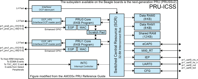
Figure 15-1: The PRU-ICSS architecture
Customized for the Beagle boards from an image that is courtesy of Texas Instruments
The PRU-ICSS subsystem that is available on the AM335x is the second-generation PRUSSv2, but not all its features are available on the Beagle board platform. In addition to the PRU cores and memory blocks, the most important blocks are illustrated in Figure 15-1, including the following:
- Enhanced GPIO (EGP): The PRU subsystem has a specific set of fast GPIOs, many of which are accessible via the BBB P8/P9 and PocketBeagle P1/P2 headers.
- OCP master port: Facilitates access to external Linux host memory. For example, this block also allows the PRUs to manipulate the state of GPIOs that are used in Chapter 6.
- Multiplier with optional accumulation (MAC): This block can be used to multiply two 32-bit operands and provide a 64-bit result.
- Interrupt controller (INTC): An interrupt controller can be used to notify each PRU that an event has occurred or to notify the host device of events (e.g., that the PRU executable program has run to completion).
- Scratch pad (SPAD): This provides three banks of 30 × 32-bit registers that are shared between the two PRU cores.
- UART0: A UART device with a dedicated 192 MHz clock is available on the Beagle board headers.
The Switched Central Resource (SCR) connects the PRUs to the other resources inside the PRU-ICSS. PRUs have access to resources on the AM335x (e.g., regular GPIOs) using the Interface/OCP master port. Linux host memory can also be used by the PRUs; however, its use is several times slower than using PRU memory, as memory access needs to be routed external to the PRU-ICSS, and back in via the PRU-ICSS Interface/OCP slave port.
The Remote Processor Framework
The Linux remote processor framework, remoteproc, is designed to allow heterogeneous multiprocessor SoCs (HMPSoCs) to control the various remote/slave processors in a unified manner. The AM335x is an HMPSoC, as the PRU-ICSS has a different hardware architecture than the Arm Cortex-A8 main processor.
The remoteproc framework allows a main processor that is running Linux to control the slave processors via OS device bindings. For example, by using the following simple commands on a Beagle board, you can turn off, load new firmware, and turn on a PRU device:
root@ebb:/sys/class/remoteproc/remoteproc1# echo 'stop' > stateroot@ebb:/sys/class/remoteproc/remoteproc1# cat stateofflineroot@ebb:…/remoteproc1# echo 'am335x-pru0-fw' > firmwareroot@ebb:…/remoteproc1# echo 'start' > stateroot@ebb:…/remoteproc1# cat staterunning
In this example, PRU0 is controlled, and the firmware from the /lib/firmware/am335x-pru0-fw file is loaded into the PRU. You can change this file at run time and thereby load new binary firmware (presently this must be in ELF32 form) to the PRU. The PRU must be stopped before you can write new PRU programs (i.e., firmware) to the device.
The remoteproc framework provides advanced features such as a remote processor messaging framework (rpmsg) that allows kernel drivers to communicate with processors. Each rpmsg device is a communication channel, termed channel, and the remote device is termed the destination rpmsg address. A driver listens to a channel, in which the receive callback is associated with a unique address value. When messages arrive, they are then dispatched by the rpmsg core to the registered driver.
Important Documents
The most important documents that are available to describe the PRU-ICSS are listed here and at the chapter web page:
- The PRU-ICSS Reference Guide: This document is the main reference for the PRU-ICSS hardware:
tiny.cc/beagle1501 - The PRU-ICSS Getting Started Guide on Linux:
tiny.cc/beagle1502 - The PRU Debugger User Guide:
tiny.cc/beagle1503 - The Remote Processor Framework:
tiny.cc/beagle1504 - The Processor Messaging Framework:
tiny.cc/beagle1505
The descriptions in this chapter refer to the preceding documents repeatedly, so it is useful to have them on hand.
Development Tools for the PRU-ICSS
Two tools must be installed to build and test the example applications that are described in this chapter, the PRU CGT and the PRU Debugger.
The PRU Code Generation Tools
Texas Instruments released the PRU Code Generation Tools (CGT) in May 2017. These development tools have full support for the remote processor framework.
- The compiler (
clpru) takes in C/C++ (C89/C99) source code and produces assembly language code. - The assembler (built in to
clpru) translates assembly language code into machine object (.object) files. - The linker (
lnkpru) combines the object files into a single executable object file (.out). This single executable object file can be executed directly on a PRU device.
The compiler can be invoked and has the general usage:
clpru [options][filenames][--run_linker[link_options] [object files]] where source filenames must be placed before the --run_linker option, and all linker options must be placed after this option. In this chapter, the clpru is called from within a Makefile file because of the significant number of required configuration options. There is further detail on the CGT at tiny.cc/beagle1506 and the compiler at tiny.cc/beagle1507.
The first step is to install the compiler on your Beagle board. Browse to www.ti.com/tool/download/PRU-CGT-2-1/ and determine the link to the latest download version. At the time of writing, this is version 2.1.5, which can be installed as follows:
debian@ebb:~$ wget http://software-dl.ti.com/codegen/esd/cgt_publ →ic_sw/PRU/2.1.5/ti_cgt_pru_2.1.5_armlinuxa8hf_busybox_installer.sh…~$ chmod ugo+x ti_cgt_pru_2.1.5_armlinuxa8hf_busybox_installer.sh…~$ sudo ./ti_cgt_pru_2.1.5_armlinuxa8hf_busybox_installer.shInstalling PRU Code Generation tools version 2.1.5 into /please wait, or press CTRL-C to abortExtracting archiveInstalling files[####################] 100%Installed successfully into /debian@ebb:~$ clpru --compiler_revision2.1.5debian@ebb:~$ whereis clpruclpru: /usr/bin/clpru
The PRU Debugger
The PRU Debugger, prudebug (sourceforge.net/projects/prudebug/), is a useful tool for identifying problems with your PRU program code. It can be executed in a separate terminal and used to view the registers when the PRU program is halted. For example, it can display the registers as follows (please note that the unusual register values in R00 to R07 result from an example in this chapter):
root@ebb:~# prudebugPRU Debugger v0.25(C)2011, 2013 by Arctica Technologies. All rights reserved.Written by Steven AndersonUsing /dev/mem device.Processor type AM335xPRUSS memory address 0x4a300000PRUSS memory length 0x00040000offsets below are in 32-bit word addresses (not ARM byte addr)PRU Instruction Data Ctrl0 0x0000d000 0x00000000 0x000088001 0x0000e000 0x00000800 0x00009000PRU0> rRegister info for PRU0Control register: 0x00000001+Reset PC:0x0000 STOPPED, FREE_RUN, COUNTER_DISABLED, NOT_SLEEPING,PROC_DISABLED Program counter: 0x003bCurrent instruction: HALTR00: 0x00010008 R08: 0xd767338a R16: 0x00000020 R24: 0x80000000R01: 0xebbfeed0 R09: 0xfcccfbf7 R17: 0xffffff50 R25: 0x733c6942R02: 0xebbfeed1 R10: 0xbaff8256 R18: 0x00000403 R26: 0x3a8215cdR03: 0xebbfeed2 R11: 0x43935b82 R19: 0x00091e38 R27: 0xaa7935e9R04: 0xebbfeed3 R12: 0x5097debd R20: 0xc0490000 R28: 0xff5fe5ddR05: 0xebbfeed4 R13: 0xb3b7db2e R21: 0x40490000 R29: 0xe6b79da6R06: 0xebbfeed5 R14: 0x00000003 R22: 0x00000000 R30: 0x00000000R07: 0xebbfeed6 R15: 0x0000003b R23: 0x00000000 R31: 0x00000000
The PRU debugger can also be used to load binaries into the PRUs, display instruction/data memory spaces, disassemble instruction memory space, and start/halt or single-step a PRU. This is useful, as it is difficult to debug programs that are running on the PRU because of the absence of a standard output. For example, you can switch PRU using the following:
PRU0> pru 1Active PRU is PRU1.
Or, you can display the current values in PRU data memory:
PRU0> DDAbsolute addr = 0x0000, offset = 0x0000, Len = 16[0x0000] 0xebbfeed0 0xebbfeed1 0x00000000 0x00000000[0x0004] 0x00000000 0x00000000 0x00000000 0x00000000[0x0008] 0x00000000 0x00000000 0x00000000 0x00000000[0x000c] 0x00000000 0x00000000 0x00000000 0x00000000
Use Q to quit the debugger, RESET to reset the current PRU, SS to single step, G to start the processor, and BR to set a breakpoint. The debugger is revisited shortly in the first PRU program example.
Using the AM335x PRU-ICSS
The PRU-ICSS is not configured for use on the Beagle boards by default; therefore, you must first enable it and test that it is working.
Setting Up the Board for Remoteproc
There are virtual capes available for the Beagle board that allow you to easily enable the PRU. The /boot/uEnv.txt configuration file allows you to choose between two PRU interfacing models, remoteproc and UIO. UIO was used in the first edition of this book but is no longer supported under the latest kernel versions.
Edit the /boot/uEnv.txt file as follows to uncomment the pru_rproc line, which should be edited to identify the device tree binary (.dtbo) for the kernel version you are currently running. In my case, I am running Linux 4.14.67, which means I must choose AM335X-PRU-RPROC-4-14-TI-00A0.dtbo from the /lib/firmware/ directory.
root@ebb:/boot# uname -r4.14.67-ti-rt-r73root@ebb:/boot# ls /lib/firmware/AM335X-PRU*/lib/firmware/AM335X-PRU-RPROC-4-14-TI-00A0.dtbo/lib/firmware/AM335X-PRU-RPROC-4-14-TI-PRUCAPE-00A0.dtbo/lib/firmware/AM335X-PRU-RPROC-4-4-TI-00A0.dtbo…/lib/firmware/AM335X-PRU-UIO-00A0.dtboroot@ebb:/boot# more uEnv.txt…###PRUSS OPTIONS###pru_rproc (4.4.x-ti kernel)#uboot_overlay_pru=/lib/firmware/AM335X-PRU-RPROC-4-4-TI-00A0.dtbouboot_overlay_pru=/lib/firmware/AM335X-PRU-RPROC-4-14-TI-00A0.dtbo###pru_uio (4.4.x-ti, 4.14.x-ti & mainline/bone kernel)#uboot_overlay_pru=/lib/firmware/AM335X-PRU-UIO-00A0.dtbo…
The PRU pins are listed in Figure 6-8 and Figure 6-9 of Chapter 6, where they are prefixed by pr1_pru0_ or pr1_pru1_. For example, P9_27/P2.34 in Figure 6-9 can be configured as a PRU input in Mode6 (pr1_pru0_pru_r31_0) and an output in Mode5 (pr1_pru0_pru_r30_0). This notation is described shortly. However, you will notice that many of the PRU pins, particularly on the BeagleBone P8 header, are already allocated to HDMI. At this point, you may also want to edit the uEnv.txt file to disable the video virtual cape.
root@ebb:~$ more /boot/uEnv.txt…###Disable auto loading of virtual capes (emmc/video/wireless/adc)#disable_uboot_overlay_emmc=1disable_uboot_overlay_video=1…
On reboot you can use the dmesg command to check for errors that have arisen as a result of your edits to the uEnv.txt configuration file. For example, a fully functioning PRU-ICSS will result in similar boot messages to the following:
root@ebb:~# dmesg |grep pru[ 279.649950] pruss 4a300000.pruss: creating PRU cores and →other child platform devices[ 279.823196] remoteproc remoteproc1: 4a334000.pru is available[ 279.823424] pru-rproc 4a334000.pru: PRU rproc node →/ocp/pruss_soc_bus@4a326004/pruss@0/pru@34000 probed successfully[ 279.919415] remoteproc remoteproc2: 4a338000.pru is available[ 279.919695] pru-rproc 4a338000.pru: PRU rproc node →/ocp/pruss_soc_bus@4a326004/pruss@0/pru@38000 probed successfully
Note that 4a334000.pru (PRU0) is associated with Linux remoteproc1 and that 4a338000.pru (PRU1) is associated with Linux remoteproc2. A call to lsmod will also list the associated LKMs.
debian@ebb:~$ lsmod|grep prupruss_soc_bus 16384 0pru_rproc 28672 0pruss 16384 1 pru_rprocpruss_intc 20480 1 pru_rproc
Testing Remoteproc under Linux
Remoteproc binds to a number of locations under sysfs, providing a straightforward mechanism for loading firmware and interacting with the individual PRUs. Once loaded, the PRUs should appear as follows, where once again 0x4a334000 is the address of PRU0 and 0x4a338000 is the address of PRU1.
root@ebb:/sys/bus/platform/drivers/pru-rproc# ls -llrwxrwxrwx 1 root root 0 Sep 6 05:54 4a334000.pru …lrwxrwxrwx 1 root root 0 Sep 6 05:54 4a338000.pru …lrwxrwxrwx 1 root root 0 Sep 6 05:54 module …--w------- 1 root root 4096 Nov 3 2016 ueventroot@ebb:/sys/bus/platform/drivers/pru-rproc# cd 4a334000.pruroot@ebb:/sys/bus/platform/drivers/pru-rproc/4a334000.pru# lsdriver driver_override modalias of_node power remoteprocsubsystem uevent
Each PRU can be controlled using its /sys/kernel/debug/ binding. For example, the following calls show the structure of these bindings, where remoteproc1 is bound to PRU0 and remoteproc2 is bound to PRU1. The entry for remoteproc0 relates to the Wakeup M3 (CM3) remoteproc driver that helps with low-power tasks on the Cortex M3 co-processor in the AM33xx family of devices—it has no role in controlling the PRU-ICSS.
root@ebb:/sys/kernel/debug/remoteproc# lsremoteproc0 remoteproc1 remoteproc2root@ebb:/sys/kernel/debug/remoteproc# cd remoteproc1root@ebb:/sys/kernel/debug/remoteproc/remoteproc1# ls -l-r-------- 1 root root 0 Sep 6 05:51 carveout_memories-r-------- 1 root root 0 Sep 6 05:51 name-r-------- 1 root root 0 Sep 6 05:51 recovery-r-------- 1 root root 0 Sep 6 05:51 regs-r-------- 1 root root 0 Sep 6 05:51 resource_table-rw------- 1 root root 0 Sep 6 05:51 single_step
Note that this provides a view of the registers that is consistent with the earlier output in this chapter from the PRU Debugger.
You can also control each PRU using its /sys/class/remoteproc/ binding, which allows you to update firmware and start and stop each PRU.
root@ebb:/sys/class/remoteproc# lsremoteproc0 remoteproc1 remoteproc2root@ebb:/sys/class/remoteproc# tree remoteproc1remoteproc1├└─ device -> ../../../4a334000.pru├└─ firmware├└─ power│ ├└─ async│ ├└─ autosuspend_delay_ms│ ├└─ control│ ├└─ runtime_active_kids│ ├└─ runtime_active_time│ ├└─ runtime_enabled│ ├└─ runtime_status│ ├└─ runtime_suspended_time│ └└─ runtime_usage├└─ state├└─ subsystem -> ../../../../../../../../class/remoteproc└└─ uevent
For example, to start and stop a PRU, you can use the following commands:
root@ebb:/sys/class/remoteproc/remoteproc1# echo 'stop' > stateroot@ebb:/sys/class/remoteproc/remoteproc1# echo 'start' > stateroot@ebb:/sys/class/remoteproc/remoteproc1# echo 'start' > state-bash: echo: write error: Device or resource busy
The PRU cannot be started twice and will give the error shown earlier should you try to do so or to write firmware to the device while it is running.
A First PRU Example
A “Hello World” LED flashing application is developed in this section so that you can quickly get started with the PRU-ICSS. The subsequent sections provide more detailed instruction and more complex examples.
PRU-ICSS Enhanced GPIOs
Each PRU has a set of GPIOs that have enhanced functionality, such as parallel-to-serial conversion. Their internal signal names have the following naming convention: pr1_pruX_pru_r3Y_Z, where X is the PRU number (0 or 1), Y defines whether the pin is an input (1) or an output (0), and Z is the pin number (0–16). For example, pr1_pru0_pru_r30_5 is output 5 for PRU0, and pr1_pru0_pru_r31_3 is input 3 for PRU0.
In Chapter 6, Figures 6-8 and 6-9 list the enhanced GPIO pins that are available on the P8/P9 and P1/P2 headers. It is clear from these figures that the pin mux must be configured in Mode5 or Mode6 using the config-pin tool to utilize these inputs/outputs. Not all the pins are exported to the P8/P9 headers on the BeagleBone or the P1/P2 headers on the PocketBeagle.
A circuit is illustrated in Figure 15-2 that uses two enhanced PRU pins. This circuit is used for several of the examples in this chapter.
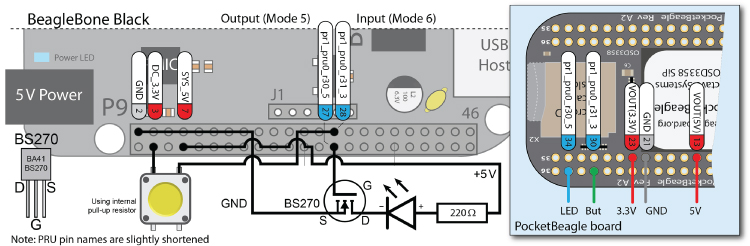
Figure 15-2: An example PRU0 circuit that uses pr1_pru0_pru_r30_5 for output and pr1_pru0_pru_r31_3 for input on the BBB and PocketBeagle boards
The pins must be configured to be in PRU mode. In this example, P9_27 (or P2.34 on the PocketBeagle) must be configured as a PRU output, as follows:
debian@ebb:~$ config-pin -l P9_27default gpio gpio_pu gpio_pd gpio_input qep pruout pruindebian@ebb:~$ config-pin P9_27 pruoutdebian@ebb:~$ config-pin -q P9_27P9_27 Mode: pruout
And, P9_28 (or P2.30 on the PocketBeagle) must be configured as a PRU input:
debian@ebb:~$ config-pin -l P9_28default gpio gpio_pu gpio_pd gpio_input spi_cs pwm pwm2 pruout pruindebian@ebb:~$ config-pin P9_28 in-debian@ebb:~$ config-pin -q P9_28P9_28 Mode: gpio_pd Direction: in Value: 0debian@ebb:~$ config-pin P9_28 pruindebian@ebb:~$ config-pin -q P9_28P9_28 Mode: pruin
A First PRU Program
The first PRU program is designed to flash the LED that is connected to pr1_pru0_pru_r30_5 (P9_27/P2.34) until a button that is connected to pr1_pru0_pru_r31_3 (P9_28/P2.30) is pressed (refer to Figure 15-2). This example is provided in C and in assembly language form.
A First PRU Program in C
The code for the PRU program is provided in Listing 15-1. This C code looks a little different than regular C code as it does not execute in Linux userspace; rather, it executes on a PRU. The LED is controlled by bit 5 in the register r30, which is accessed as hexadecimal 0x0000 0020 (i.e., 1000002). Similarly, the button is controlled by bit 3 in the register r31, which is accessed as hexadecimal 0x0000 0008 (i.e., 10002). Please refer to the “Bit Manipulation in C/C++” feature in Chapter 6 for further details on the bitwise operations, which are performed in these examples.
Listing 15-1: /exploringbb/chp15/pru/ledFlash/ledFlash.c
/* Source Modified by Derek Molloy for Exploring BeagleBone Rev2* Based on the examples distributed by Texas Instruments */#include <stdint.h>#include <pru_cfg.h>#include "resource_table_empty.h"volatile register uint32_t __R30; // output gpio registervolatile register uint32_t __R31; // input gpio registervoid main(void) {volatile uint32_t led, button; // for bit identifiers// Use pru0_pru_r30_5 as an output i.e., 100000 or 0x0020led = 0x0020;// Use pru0_pru_r31_3 as a button i.e., 1000 or 0x0008button = 0x0008;// Stop the loop when the button is pressedwhile (!(__R31 && button)) { // while button bit not set__R30 ^= led; // invert/flash the LED bit// delay for approx. 0.25s (one quarter second)__delay_cycles(50000000);}__halt(); // end the program}
The C program in Listing 15-1 is placed in a project directory with the following files:
Makefilehas all the build options for the project. You can callmake,make cleanto clear build files, andmake install_PRUxto deploy the binary executable to a PRU.AM335x_PRU.cmdis a linker command file for linking PRU programs built with the compiler. It contains the memory map and definition for the PRU architecture.resource_table_empty.his required by remoteproc to define the required resource table for the PRU cores.
debian@ebb:~/exploringbb/chp15/pru/ledFlashC$ ls -l-rw-r--r-- 1 debian debian 3505 Sep 7 05:29 AM335x_PRU.cmd-rw-r--r-- 1 debian debian 2326 Sep 18 00:09 ledFlash.c-rw-r--r-- 1 debian debian 3616 Sep 7 05:29 Makefile-rw-r--r-- 1 debian debian 2789 Sep 7 05:29 resource_table_empty.h
This project can be built using the Makefile file as follows:
…/chp15/pru/ledFlashC$ makeBuilding project: ledFlashCBuilding file: ledFlash.cInvoking: PRU Compiler/usr/bin/clpru --include_path=/usr/lib/ti/pru-software-support-package/include--include_path=/usr/lib/ti/pru-software-support-package/include --include_path=/usr/lib/ti/pru-software-support-package/include/am335x -v3 -O2--display_error_number --endian=little --hardware_mac=on --obj_directory=gen--pp_directory=gen -ppd -ppa -fe gen/ledFlash.object ledFlash.cBuilding target: gen/ledFlashC.outInvoking: PRU Linker/usr/bin/clpru -v3 -O2 --display_error_number --endian=little --hardware_mac=on--obj_directory=gen --pp_directory=gen -ppd -ppa -z-i/usr/lib/ti/pru-software-support-package/lib-i/usr/lib/ti/pru-software-support-package/include --reread_libs--warn_sections --stack_size=0x100 --heap_size=0x100 -o gen/ledFlashC.outgen/ledFlash.object -mgen/ledFlashC.map ./AM335x_PRU.cmd --library=libc.a--library=/usr/lib/ti/pru-software-support-package/lib/rpmsg_lib.lib<Linking>Finished building target: gen/ledFlashC.outOutput files can be found in the "gen" directoryFinished building project: ledFlashC
and then deployed to PRU0 using make install_PRU0:
…/chp15/pru/ledFlashC$ sudo make install_PRU0Stopping current PRU0 application (/sys/class/remoteproc/remoteproc1)Stop… Installing firmware… Deploying firmware…am335x-pru0-fw… Starting new PRU0 application… Start
Effectively, this Makefile builds a binary ledFlashC.out in the gen/ directory, which is then copied to /lib/firmware/am335x-pru0-fw (hence the superuser requirement). In the same manner as previously described in this chapter, the PRU0 is stopped, the firmware file is written to PRU0 program memory, and then it is restarted.
…/chp15/pru/ledFlashC$ cd gen…/chp15/pru/ledFlashC/gen$ lsledFlashC.map ledFlashC.out ledFlash.object ledFlash.pp…/chp15/pru/ledFlashC/gen$ ls -l ledFlashC.out-rw-r--r-- 1 debian debian 32284 Sep 18 01:15 ledFlashC.out…/chp15/pru/ledFlashC/gen$ cd ..…/chp15/pru/ledFlashC$ ls -l /lib/firmware/am335x-pru0-fw-rw-r--r-- 1 root root 32284 Sep 18 01:14 /lib/firmware/am335x-pru0-fw
A First PRU Program in Assembly
It is also possible to write this program in assembly language, which is sometimes more straightforward when designing timing-critical programs. The assembly code has the extension .asm, but you still require a C container program, such as that provided in Listing 15-2.
Listing 15-2: /exploringbb/chp15/pru/ledFlashASM/main.c
#include <stdint.h>#include <pru_cfg.h>#include "resource_table_empty.h"// the function is defined in ledFlashASM.asm in same dir// declaration is here, definition is linked to the .asmextern void start(void); // not defined here, but in the .asmvoid main(void) {START(); // call START in ledFlashASM.asm}
The flash LED code in the project ledFlashASM.asm uses raw assembly code in Listing 15-3. The LED is turned on for 50 ms and then off for 50 ms, which means that the LED will flash at 10 Hz (i.e., 10 times per second), resulting in the output shown in Figure 15-4.
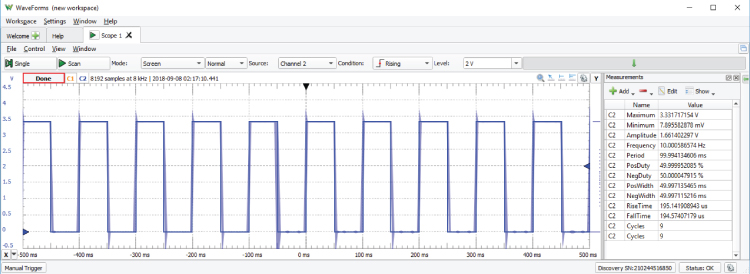
Figure 15-4: Flashing an LED cleanly at 10 Hz
Listing 15-3: /exploringbb/chp15/pru/ledFlashASM/ledFlashASM.asm
.cdecls "main.c".clink.global START.asg "5000000", DELAY ; hard define the DELAYSTART:SET r30, r30.t5 ; set the output LED pin (LED on)LDI32 r0, DELAY ; load the delay value into REG0DELAYON:SUB r0, r0, 1 ; subtract 1 from the REG0 valueQBNE DELAYON, r0, 0 ; loop to DELAYON, unless REG0=0LEDOFF:CLR r30, r30.t5 ; clear the output pin (LED off)LDI32 r0, DELAY ; Reset REG0 to the length of the delayDELAYOFF:SUB r0, r0, 1 ; decrement REG0 by 1QBNE DELAYOFF, r0, 0 ; loop to DELAYOFF, unless REG0=0QBBC START, r31, 3 ; is the button pressed? If not, loopEND:HALT ; halt the pru program
Details about the available assembly language instructions are provided later in this chapter, but the important instructions that are used in Listing 15-3 are as follows:
SET r30.t5: Sets bit 5 on register 30 to be high. REG30 is used to set the PRU0 GPIO pins high. Bit 5 specifically controls thepr1_pru0_pru_r30_5pin output.-
LDI32 r0, DELAY: Loads the 32-bit delay value (i.e., 5,000,000) in the register REG0. Registers are used here, just as variables are used in C. Assembly operations are performed on registers. DELAYON: A user-defined label to which the code can branch.SUB r0, r0, 1: Subtracts1from REG0 and stores the result in REG0. It is essentially the same as the codeREG0=REG0-1.QBNE DELAYON, r0, 0: Performs a quick branch if REG0 is not equal to 0. This creates a loop that loops these two instructions 5,000,000 times (taking exactly 50ms!).CLR r30, r30.t5: Clears bit 5 on register 30, setting the output low and turning the LED off.QBBC START, r31.t3: Does a quick branch toSTARTif ther31.t3bit is clear (i.e.,0). REG31 is the input register that is used to read the state of the input—t3is bit 3, which is connected to thepr1_pru0_pru_r31_3pin. As the button input pin is configured to have a pull-down resistor enabled, it will return0when it is not pressed and1when it is pressed. If the button is not pressed, then the program loops forever, continually flashing the LED. When the button is first found to be in the pressed state at this point during program execution, then the program continues to the next line.- The program then ends with the call to
HALT.
This program can be built using a call to the make command and then deployed to a PRU of your choice as follows:
…/chp15/pru/ledFlashASM$ make…/chp15/pru/ledFlashASM$ sudo make install_PRU0
resulting in a file ledFlashASM.out in the gen/ directory.
Each time that the program is executed, the LED will flash at 10 Hz until the button is pressed. One impressive feature of this application is the regularity of the output signal, which can be observed when the circuit is connected to an oscilloscope. Figure 15-4 illustrates the output and the frequency measurements, and it is clear from the measurements that the signal does not suffer from the jitter issues that affect a similar circuit in Chapter 6. Also, the program is running with almost no Linux overhead.
The PRU-ICSS in Detail
It is useful to have a working example in place, but some features of the PRU-ICSS must be covered in more detail to ensure that you can write your own applications that build on the preceding example.
Registers
In the previous example, one register (REG0) is used as the memory location in which to store and decrement the time delay. Registers provide the fastest way to access data—assembly instructions are applied to registers, and they complete in a single clock cycle. However, each PRU core has 32 registers (0–31). Registers REG1 to REG29 are general-purpose registers, whereas REG30 and REG31 are special-purpose registers, and REG0 is used for indexing (or as a general-purpose register). It should be noted that 30 general-purpose registers is a generous number for a microcontroller, as these registers can be reused repeatedly. For example, in the previous PRU program, both delays are performed using a single register.
Register values are 32-bit variables that can be accessed using a suffix notation, which is illustrated in Figure 15-5. In Listing 15-3, shown earlier, bit 5 of REG30 is accessed using r30.t5. There are three suffixes.
- word
.wn (where n is 0…2) - byte
.bn (where n is 0…3) - bit
.tn (where n is 0…31)
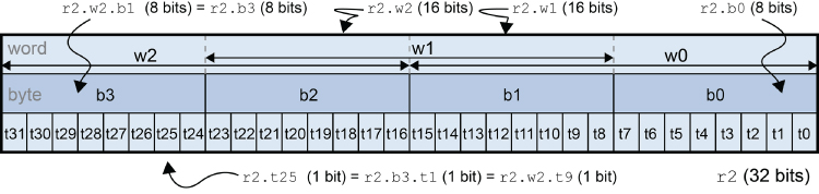
Figure 15-5: PRU register bit field notation
It is important to note that there are three word indices—w1 is offset by eight bits and therefore overlaps half the contents of w0 and w2. Figure 15-5 also provides some usages—for example, r2.w1.b1 requests byte 1 of word 1, which is eight bits in length (i.e., bits 16 to 23 of r2). This is equivalent to a request for r2.b2 (eight bits), but it is not equivalent to r2.w2, which has the same starting address but is 16 bits in length. Examples of illegal register calls include r2.w2.b2, r2.t4.b1, r2.w1.t16, and r2.b0.b0.
REG31 is called the PRU Event/Status Register (r31). It is a particularly complex register, which behaves differently depending on whether you are writing to it or reading from it. When writing to REG31, it provides a mechanism for sending output events to the Interrupt Controller (INTC). By writing an event number (0 to 31) to the five LSBs (PRU_VEC[4:0]) and setting bit 5 (PRU_VEC_VALID) high, an output event can be sent to the Linux host.
When reading from REG31, it provides the state of the enhanced GPIO inputs. For example, in Listing 15-3, the line QBBC START, r31.t3 reads bit 3 from REG31 to determine whether the button is in a pressed state. Essentially, it reads the state of the GPIO that is connected to bit 3.
REG30 is used by the PRU to set enhanced GPIO outputs. For example, in Listing 15-3, the line SET r30.t5 is used to set bit 5 of REG30 high. In turn, this results in the associated GPIO output switching the LED on.
Local and Global Memory
The PRUs have general-purpose local memory that can be used by PRU programs to store and retrieve data. Because this local PRU memory is mapped to a global address space on the Linux host, it can also be used to share data between PRU programs and programs running on the Linux host. Figure 15-6 illustrates the memory mappings.
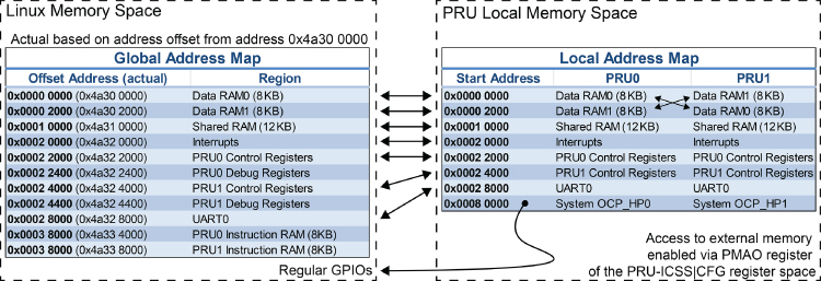
Figure 15-6: The PRU-ICSS memory address maps
Image created from data that is courtesy of Texas Instruments
It is important to note that there is a slight difference between the PRU memory spaces. PRU0 accesses its primary memory (Data RAM0) at address 0x0000 0000, and PRU1 also accesses its primary memory (Data RAM1) at address 0x0000 0000. However, each PRU can also access the data RAM of the other PRU at address 0x0000 2000. In addition, 12 KB of shared memory can be used by both PRUs at the local address 0x0001 0000. The PRU cores can also use the global memory map, but there is latency as access is routed through the OCP slave port (refer to Figure 15-1).
Listing 15-4 is a short C program that uses PRU0 to write seven 32-bit values to three different memory locations, PRU0 memory, PRU1 memory, and the shared PRU memory. The addresses of each of these memory locations is illustrated in Figure 15-6. The values were chosen to be clearly identifiable, that is, 0xEBBFEEDx.
Listing 15-4: /exploringbb/chp15/pru/pruTest/pruTest.c
#include <stdint.h>#include <pru_cfg.h>#include "resource_table_empty.h"#define PRU0_DRAM 0x00000000volatile uint32_t *pru0Mem = (unsigned int *) PRU0_DRAM;#define PRU1_DRAM 0x00002000volatile uint32_t *pru1Mem = (unsigned int *) PRU1_DRAM;#define SHARE_MEM 0x00010000volatile uint32_t *shared = (unsigned int *) SHARE_MEM;extern void start(void);void main(void) {pru0Mem[0] = 0xEBBFEED0;pru0Mem[1] = 0xEBBFEED1;pru1Mem[0] = 0xEBBFEED2;pru1Mem[1] = 0xEBBFEED3;shared[0] = 0xEBBFEED4;shared[1] = 0xEBBFEED5;shared[2] = 0xEBBFEED6;start();}
The code in Listing 15-5 is a PRU program that is started by the call to start() in Listing 15-4. This assembly program simply loads the registers r1 to r7 with the values in the different memory locations. The register r0 is used as a temporary register that stores the address value to load.
Listing 15-5: /exploringbb/chp15/pru/pruTest/pruTest.asm
.cdecls "pruTest.c".clink.global startstart:LDI32 r0, 0x00000000 ; load r0 with the PRU0 address to loadLBBO &r1, r0, 0, 4 ; load r1 with value at r0 EBBFEED0LDI32 r0, 0x00000004 ; load r0 with the next PRU0 addressLBBO &r2, r0, 0, 4 ; load r2 with the EBBFEED1LDI32 r0, 0x00002000 ; load r0 with the PRU1 address to loadLBBO &r3, r0, 0, 4 ; load r3 with value at r0 EBBFEED2LDI32 r0, 0x00002004 ; load r0 with the next PRU1 addressLBBO &r4, r0, 0, 4 ; load r4 with the EBBFEED3LDI32 r0, 0x00010000 ; load r0 with the shared addressLBBO &r5, r0, 0, 4 ; load r5 with the EBBFEED4LDI32 r0, 0x00010004 ; load r0 with the next shared addressLBBO &r6, r0, 0, 4 ; load r6 with the EBBFEED5LDI32 r0, 0x00010008 ; load r0 with the next shared addressLBBO &r7, r0, 0, 4 ; load r7 with the EBBFEED6HALT
The project can be built and executed using the following:
debian@ebb:~/exploringbb/chp15/pru/pruTest$ makedebian@ebb:~/exploringbb/chp15/pru/pruTest$ sudo make install_PRU0
Once this code is executed, you can access the memory addresses from Linux userspace using the devmem2 tool and the address map in Figure 15-6, which results in the following:
debian@ebb:~/exploringbb/chp15/pru/pruTest$ sudo -iroot@ebb:~# /home/debian/devmem2 0x4a300000Memory mapped at address 0xb6f6a000.… Value at address 0x4A300000 (0xb6f6a000): 0xEBBFEED0root@ebb:~# /home/debian/devmem2 0x4a300004… Value at address 0x4A300004 (0xb6fe8004): 0xEBBFEED1root@ebb:~# /home/debian/devmem2 0x4a302000… Value at address 0x4A302000 (0xb6fe3000): 0xEBBFEED2root@ebb:~# /home/debian/devmem2 0x4a302004… Value at address 0x4A302004 (0xb6f03004): 0xEBBFEED3root@ebb:~# /home/debian/devmem2 0x4a310000… Value at address 0x4A310000 (0xb6fae000): 0xEBBFEED4root@ebb:~# /home/debian/devmem2 0x4a310004… Value at address 0x4A310004 (0xb6f51004): 0xEBBFEED5root@ebb:~# /home/debian/devmem2 0x4a310008… Value at address 0x4A310008 (0xb6feb008): 0xEBBFEED6
The preceding values confirm that the mappings in Figure 15-6 are correct and that devmem2 is useful for verifying that the values in memory are as expected. Remember that it can also be used to write to memory locations.
You can use the remoteproc register view to confirm that the registers have been loaded, as described in Listing 15-5.
root@ebb:/sys/kernel/debug/remoteproc/remoteproc1# cat regs============== Control Registers ==============CTRL := 0x00000001STS (PC) := 0x0000003b (0x000000ec)…=============== Debug Registers ===============GPREG0 := 0x00010008 CT_REG0 := 0x00020000GPREG1 := 0xebbfeed0 CT_REG1 := 0x48040000GPREG2 := 0xebbfeed1 CT_REG2 := 0x4802a000GPREG3 := 0xebbfeed2 CT_REG3 := 0x00030000GPREG4 := 0xebbfeed3 CT_REG4 := 0x00026000GPREG5 := 0xebbfeed4 CT_REG5 := 0x48060000GPREG6 := 0xebbfeed5 CT_REG6 := 0x48030000GPREG7 := 0xebbfeed6 CT_REG7 := 0x00028000 …
You can also use the PRU debugger to confirm the same register and memory values.
root@ebb:~# prudebugPRU Debugger v0.25(C)2011, 2013 by Arctica Technologies. All rights reserved.Written by Steven AndersonUsing /dev/mem device.Processor type AM335xPRUSS memory address 0x4a300000PRUSS memory length 0x00040000offsets below are in 32-bit word addresses (not ARM byte addresses)PRU Instruction Data Ctrl0 0x0000d000 0x00000000 0x000088001 0x0000e000 0x00000800 0x00009000PRU0> ddAbsolute addr = 0x0000, offset = 0x0000, Len = 16[0x0000] 0xebbfeed0 0xebbfeed1 0x00000000 0x00000000…PRU0> rRegister info for PRU0Control register: 0x00000001Reset PC:0x0000 STOPPED, FREE_RUN, COUNTER_DISABLED,NOT_SLEEPING, PROC_DISABLEDProgram counter: 0x003bCurrent instruction: HALTR00: 0x00010008 R08: 0xd767338a R16: 0x00000020 R24: 0x80000000R01: 0xebbfeed0 R09: 0xfcccfbf7 R17: 0xffffff50 R25: 0x733c6942R02: 0xebbfeed1 R10: 0xbaff8256 R18: 0x00000403 R26: 0x3a8215cdR03: 0xebbfeed2 R11: 0x43935b82 R19: 0x00091e38 R27: 0xaa7935e9R04: 0xebbfeed3 R12: 0x5097debd R20: 0xc0490000 R28: 0xff5fe5ddR05: 0xebbfeed4 R13: 0xb3b7db2e R21: 0x40490000 R29: 0xe6b79da6R06: 0xebbfeed5 R14: 0x00000003 R22: 0x00000000 R30: 0x00000000R07: 0xebbfeed6 R15: 0x0000003b R23: 0x00000000 R31: 0x00000000
The PRUs have a constants table, which contains a list of commonly used addresses that are often used in memory load and store operations. This reduces the time required to load memory pointers into registers. Most of the constants are fixed, but some are programmable by using PRU control registers. The constants table is utilized later so that the PRU can access regular GPIOs that are outside the PRU-ICSS.
PRU Assembly Instruction Set
The PRU-ICSS has a relatively small RISC instruction set architecture (ISA), with approximately 45 instructions that can be categorized as arithmetic operations, logical operations, register load and store, and program flow control. A summary description of each of the instructions is provided in Figure 15-7. The full description of each instruction is available in the PRU-ICSS Reference Guide.
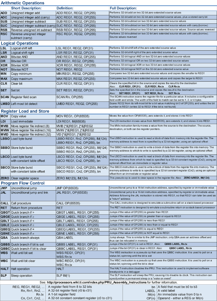
Figure 15-7: Summary of the PRU instruction set
Image created from information that is courtesy of Texas Instruments
Instructions consist of an operation code (opcode) and a variable number of operands, where the third operand can often be a register or an immediate value (a simple number or an expression that evaluates to a constant value). Here's an example:
ADD REG1, REG2, OP(255) where ADD is a mnemonic that evaluates to an opcode (e.g., 0x01 for ADD), REG1 is the target register, REG2 is a source register, and OP(255) can be another register field or an immediate value—it must be, or evaluate to, the range of 010 to 25510 for the ADD operation. Here are some example usages (see the chp15/pru/testASM/ project):
LDI32 r1, 0x25 ; set r1 = 0x25 = 37 (dec)LDI32 r2, 4 ; set r2 = 4 (dec)ADD r1, r1, 5 ; set r1 = r1 + 5 = 42 (dec)ADD r2, r2, 1<<4 ; set r2 = r2 + 10000 (bin) = 20 (dec)ADD r1, r2, r1.w0 ; set r1 = r2 + r1.w0 = 20 + 42 = 62 (dec)LDI32 r0, 0x00002000 ; place PRU1 data RAM1 base address in r0SBBO &r1, r0, 4, 4 ; write r1 to the address that is stored in r0; offset = 4 bytes, size of data = 4 bytes
If this example is run on PRU0, the value of r1 (6210 = 0x3e) is written to the PRU1 Data RAM1, which is at address 0x0000 2000 in the PRU1 memory space, and is at 0x4A30 2000 in Linux host memory space. The value is written at an offset of four bytes, so it appears at the address 0x4A30 2004 in the Linux host memory space. This code segment does not overwrite the 0xEBBFE ED2 value (from the previous example) when an offset of four bytes is used:
root@ebb:~# /home/debian/devmem2 0x4a302000Value at address 0x4A302000 (0xb6fd9000): 0xEBBFEED2root@ebb:~# /home/debian/devmem2 0x4a302004Value at address 0x4A302004 (0xb6f85004): 0x3E
PRU-ICSS Applications
In this section, several example applications are developed to test the performance of the PRU-ICSS and to illustrate how you can build Linux host applications that interact with it. Each application introduces additional features of the PRU-ICSS, so it is important that you read each one, even if you do not intend to build that particular type of application.
PRU-ICSS Performance Tests
In Chapter 6, a test is described that evaluates the performance of a Linux user space C/C++ application that lights an LED when a button is pressed. A similar set of tests is presented here that use the PRU-ICSS. All these tests use the circuit illustrated in Figure 15-2. The tests are as follows:
- The assembly button press, LED response test is available in the
/chp15/pru/perfTestASM/directory and in Listing 15-6. This test aims to evaluate the fastest response of a PRU to an input when the code is written in assembly language. - The C button press, LED response test is available in the
/chp15/pru/perfTest/directory and in Listing 15-7. This test aims to evaluate the fastest response of a PRU to an input when the code is written in the C programming language. - The high-frequency LED flash test is available in the
/chp15/pru/blinkLED/directory and in Listing 15-8. This test aims to consistently flash an LED at a frequency of 1 MHz.
These tests stretch the capabilities of the Analog Discovery (5 MHz, 50 MSPS). The sample values are represented by “x” markers in Figure 15-8, which are spaced at 10 ns intervals (curve fitting is used to display the outputs). Despite the shortcomings of the Analog Discovery, the graphs are indicative of the high-performance capability of the PRU-ICSS.
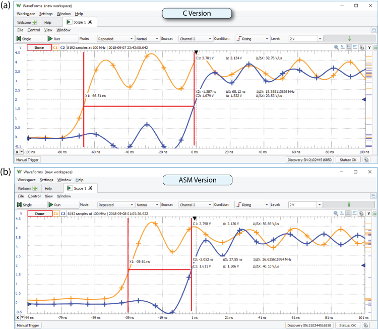
Figure 15-8: The button press LED response test, written in (a) C and (b) assembly language
Each of these tests is an individual project and executable binary. The comments in each code listing describe how the test is performed.
Listing 15-6: /chp15/pru/perfTestASM/perfTestASM.asm
.cdecls "perfTestContainer.c".clink.global startstart:CLR r30, r30.t5 ; turn off the LEDWBS r31, 3 ; wait bit set - i.e., button pressSET r30, r30.t5 ; set the output bit - turn on the LEDHALT
Listing 15-7: /chp15/pru/perfTest/perfTest.c
#include <stdint.h>#include <pru_cfg.h>#include "resource_table_empty.h"volatile register uint32_t __R30;volatile register uint32_t __R31;void main(void) {volatile uint32_t led, button;// Use pru0_pru_r30_5 as an output i.e., 100000 or 0x0020led = 0x0020;// Use pru0_pru_r31_3 as a button i.e., 1000 or 0x0008button = 0x0008;// Turn the LED off__R30 &= !led;// Stop the loop when the button is pressedwhile (!(__R31 && button)) {// Do nothing}// Turn the LED on__R30 ^= led;__halt();}
Listing 15-8: /chp15/pru/perfTestLED/perfTestLED.asm
.cdecls "main.c".clink.global START.asg "48", DELAY ; needs to account for control logicSTART:SET r30, r30.t5LDI32 r0, DELAYDELAYON:SUB r0, r0, 1QBNE DELAYON, r0, 0 ; loop to DELAYON, unless REG0=0LEDOFF:CLR r30, r30.t5 ; clear the output bin (LED off)LDI32 r0, DELAY ; reset REG0 to the length of the delayDELAYOFF:SUB r0, r0, 1 ; decrement REG0 by 1QBNE DELAYOFF, r0, 0 ; loop to DELAYOFF, unless REG0=0QBBC START, r31, 3 ; is the button pressed? If not, loopEND: ; notify the calling app that finishedHALT ; halt the pru program
The results for each of the tests are as follows:
- For the pure assembly program in Listing 15-7, the LED lights approximately 39 ns after the button is pressed (31 ns when a high-resolution oscilloscope is used)—see Figure 15-8(b). To put this number in context, in this time a light pulse would have traveled approximately 9 meters through free space (at 3×10⁸ m/s) and sound would have traveled 100th of a mm in air (340 m/s at sea level). The latter means that this time resolution, coupled with suitable acoustic sensor(s), makes accurate distance measurements feasible with the PRU-ICSS. Figure 15-9(a) confirms the measurement of the Analog Discovery using a higher bandwidth oscilloscope.
- For the C program, the LED lights approximately 67 ns after the button is pressed—see Figure 15-8(a). This is an impressive result for code that has been automatically compiled to assembly.
- The LED test, as indicated in Figure 15-9(b), indicates that each PRU can be used to output user-configurable signals at very high frequencies (note that the PRU-ICSS also has dedicated clock outputs—e.g., a 192 MHz UART clock).
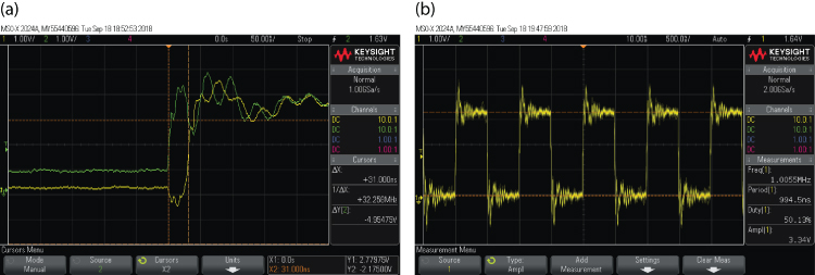
Figure 15-9: Measurements using a 20 MHz scope: (a) button press assembly test, (b) LED test at a blink frequency of 1MHz
Importantly, none of these tests has a significant CPU or memory load on the Linux host. To run these tests, choose the test directory (perfTest, perfTestASM, or perfTestLED) and then use the following:
debian@ebb:…/chp15/pru/perfTestASM$ makedebian@ebb:…/chp15/pru/perfTestASM$ sudo make install_PRU0
Utilizing Regular Linux GPIOs
Each PRU is attached to an OCP master port, as illustrated in Figure 15-1, which permits access to memory addresses on the Linux host device. This functionality allows the PRUs to manipulate the state of the regular GPIOs that are used in Chapter 6. The first step is to enable the OCP master port using the following instructions:
LBCO &r0, C4, 4, 4 ; load SYSCFG reg into r0 (use c4 const addr)CLR r0, r0, 4 ; clear bit 4 (STANDBY_INIT)SBCO &r0, C4, 4, 4 ; store the modified r0 back at the load addr
Here, c4 refers to entry 4 in the constants table, which is the PRU_ICSS CFG (local) address. Therefore, offset 4 refers to the SYSCFG register. The CLR instruction sets bit 4 (STANDBY_INIT) to be 0, thus enabling the OCP master ports when r0 is written back to the SYSCFG register using the SBCO (store byte burst with constant table offset) instruction.
The next step is to determine the explicit Linux host memory addresses for the GPIOs—this is described in the feature “Memory-Based GPIO Switching” in Chapter 6. The GPIO bank addresses and states can be defined using the following addresses and offsets:
.asg 0x44e07000, GPIO0 ; GPIO Bank 0, See the AM335x TRM.asg 0x4804c000, GPIO1 ; GPIO Bank 1, Table 2.2 Peripheral Map.asg 0x481ac000, GPIO2 ; GPIO Bank 2,.asg 0x481ae000, GPIO3 ; GPIO Bank 3,.asg 0x190, GPIO_CLRDATAOUT; for clearing the GPIO registers.asg 0x194, GPIO_SETDATAOUT; for setting the GPIO registers.asg 0x138, GPIO_DATAIN ; for reading the GPIO registers.asg 1<<30, GPIO0_30 ; P9_11 gpio0[30] Output - bit 30.asg 1<<31, GPIO0_31 ; P9_13 gpio0[31] Input - bit 31
The PRU code is provided in Listing 15-9. It is similar to Listing 15-8, with the exception that the GPIO addresses must be loaded into registers and manipulated at the bit level. The C code is not listed here, as it is similar to Listing 15-2. However, the full project is available in the /chp15/pru/ledFlashASM_OCP/ repository directory.
Listing 15-9: /chp15/pru/ledFlashASM_OCP/ledFlashASM_OCP.asm
; This program flashes an LED on P9_11/P2.05 until a button that is; attached to P9_13/P2.07 is pressed..cdecls "main.c".clink.global START.asg "5000000", DELAY.asg 0x44e07000, GPIO0 ; GPIO Bank 0, See the AM335x TRM.asg 0x4804c000, GPIO1 ; GPIO Bank 1, Table 2.2 Peripheral Map.asg 0x481ac000, GPIO2 ; GPIO Bank 2,.asg 0x481ae000, GPIO3 ; GPIO Bank 3,.asg 0x190, GPIO_CLRDATAOUT ; for clearing the GPIO registers.asg 0x194, GPIO_SETDATAOUT ; for setting the GPIO registers.asg 0x138, GPIO_DATAIN ; for reading the GPIO registers.asg 1<<30, GPIO0_30 ; P9_11/P2.05 gpio0[30] Output - bit 30.asg 1<<31, GPIO0_31 ; P9_13/P2.07 gpio0[31] Input - bit 31.asg 32, PRU0_R31_VEC_VALID ; allows notification of program completion.asg 3, PRU_EVTOUT_0 ; the event number that is sent backSTART:; Enable the OCP master portLBCO &r0, C4, 4, 4 ; load SYSCFG reg into r0 (use c4 const addr)CLR r0, r0, 4 ; clear bit 4 (STANDBY_INIT)SBCO &r0, C4, 4, 4 ; store the modified r0 back at the load addrMAINLOOP:LDI32 r1, (GPIO0|GPIO_SETDATAOUT) ; load addr for GPIO Set data r1LDI32 r2, GPIO0_30 ; write GPIO0_30 to r2SBBO &r2, r1, 0, 4 ; write r2 to the r1 address value - LED ONLDI32 r0, DELAY ; store the length of the delay in REG0DELAYON:SUB r0, r0, 1QBNE DELAYON, r0, 0 ; Loop to DELAYON, unless REG0=0LEDOFF:LDI32 r1, (GPIO0|GPIO_CLRDATAOUT) ; load addr for GPIO Clear dataLDI32 r2, GPIO0_30 ; write GPIO_30 to r2SBBO &r2, r1, 0, 4 ; write r2 to the r1 address - LED OFFLDI32 r0, DELAY ; Reset REG0 to the length of the delayDELAYOFF:SUB r0, r0, 1 ; decrement REG0 by 1QBNE DELAYOFF, r0, 0 ; Loop to DELAYOFF, unless REG0=0LDI32 r5, (GPIO0|GPIO_DATAIN) ; load read addr for DATAOUTLBBO &r6, r5, 0, 4 ; Load the value at r5 into r6QBBC MAINLOOP, r6, 31 ; is the button pressed? If not, loopEND: ; notify that finishedLDI32 R31, (PRU0_R31_VEC_VALID|PRU_EVTOUT_0)HALT ; halt the pru program
There are two regular GPIO pins, P9_11/P2.05 (output) and P9_13/P2.07 (input). The P9_11/P2.05 pin should be connected to the FET gate input, and P9_13/P2.07 should be connected to the button, as described in Figure 15-2. Ensure that the GPIOs are configured as follows, before the application is executed:
root@ebb:~/PRU# config-pin -a P9_11 outroot@ebb:~/PRU# config-pin -q P9_11P9_11 Mode: gpio Direction: out Value: 0root@ebb:~/PRU# config-pin -a P9_11 hiroot@ebb:~/PRU# config-pin -a P9_11 loroot@ebb:~/PRU# config-pin -q P9_13 in-P9_13 Mode: default Direction: in Value: 0
When executed, the code will provide output similar to that shown in Figure 15-9(b).
…/chp15/pru/ledFlashASM_OCP$ make…/chp15/pru/ledFlashASM_OCP$ sudo make install_PRU0
A PRU PWM Generator
As described in Chapter 6, PWM has many applications, such as motor and lighting control, and there is hardware PWM support available on the Beagle boards that can be accessed directly from Linux user space. However, sysfs is slow at adjusting the duty cycle, and it is prone to the same type of latency issues as regular GPIOs. In the next section, PWM is used to output a sine wave signal by rapidly changing the duty cycle of a high-frequency switched digital output cyclically as a function of time. In this section, we prepare for that application by setting up a square waveform with a constant duty cycle.
Listing 15-10 is the Linux container code for the assembly code. It also uses the main() function to transfer the PWM duty cycle percentage and the delay factor (i.e., how many instructions × 5 ns there should be for each of the 100 samples per period). The values passed by the code in Listing 15-10 result in a PWM signal with a duty cycle of 75 percent and a period of approximately 11 µs (i.e., 100 samples per period × 10 delay steps per sample × 2 instructions per delay × 5 ns per instruction + looping overhead).
Listing 15-10: /exploringbb/chp15/pru/pwm/main.c
#include <stdint.h>#include <pru_cfg.h>#include <pru_ctrl.h>#include "resource_table_empty.h"#define PRU0_DRAM 0x00000volatile unsigned int *shared = (unsigned int *)(PRU0_DRAM);extern void START(void);void main(void) {// Copy the PWM percentage (0-100) and delay factor into PRU memoryshared[0] = 75;// Delay factor -- write it into the next word location in// memory (i.e.,4-bytes later)shared[1] = 10;START();}
The assembly code is provided in Listing 15-11. It consists of a main loop that loops once for each signal period, until a button that is attached to r31.t3 is pressed. Within the main loop are two nested loops. One iterates for the number of samples that the signal is high, and the second iterates for the number of samples that the signal is low. The total number of nested iterations is 100, where each iteration has a user-configurable delay.
Listing 15-11: /exploringbb/chp15/pru/pwm/pwm.asm
; Written for Exploring BeagleBone v2 by Derek Molloy; This program uses the PRU as a PWM controller based on the values in; 0x00000000 (percentage) and 0x00000004 (delay).cdecls "main.c".clink.global START.asg 32, PRU0_R31_VEC_VALID ; allows notification of program completion.asg 3, PRU_EVTOUT_0 ; the event number that is sent backSTART:; Reading the memory that was set by the C program into registers; r1 - Read the PWM percent high (0-100)LDI32 r0, 0x00000000 ; load the memory locationLBBO &r1, r0, 0, 4 ; load the percent value into r1; r2 - Load the sample time delayLDI32 r0, 0x00000004 ; load the memory locationLBBO &r2, r0, 0, 4 ; load the step delay value into r2; r3 - The PWM percent that the signal is low (100-r1)LDI32 r3, 100 ; load 100 into r3SUB r3, r3, r1 ; subtract r1 (high) away from 100MAINLOOP:MOV r4, r1 ; start counter at number of steps highSET r30, r30.t5 ; set the output P9_27/P2.34 highSIGNAL_HIGH:MOV r0, r2 ; the delay step length - load r2 aboveDELAY_HIGH:SUB r0, r0, 1 ; decrement delay loop counterQBNE DELAY_HIGH, r0, 0 ; repeat until step delay is doneSUB r4, r4, 1 ; the signal was high for a stepQBNE SIGNAL_HIGH, r4, 0 ; repeat until signal high steps are done; Now the signal is going to go low for 100%-r1% - i.e., r3MOV r4, r3 ; number of steps low loadedCLR r30, r30.t5 ; set the output P9_27/P2.34 lowSIGNAL_LOW:MOV r0, r2 ; the delay step length - load r2 aboveDELAY_LOW:SUB r0, r0, 1 ; decrement loop counterQBNE DELAY_LOW, r0, 0 ; repeat until step delay is doneSUB r4, r4, 1 ; the signal was low for a stepQBNE SIGNAL_LOW, r4, 0 ; repeat until signal low % is doneQBBS END, r31, 3 ; quit if button on P9_28/P2.30 is pressedQBA MAINLOOP ; otherwise loop foreverEND: ; end of program, send back interruptLDI32 R31, (PRU0_R31_VEC_VALID|PRU_EVTOUT_0)HALT ; halt the pru program
The circuit is wired as shown in Figure 15-2, and the same pin configuration is used for this example. The output of the circuit is displayed in Figure 15-10. A simple low-pass filter is added to the P9_27/P2.34 output pins, and it results in the “Low-pass filtered output” signal in Figure 15-2. In this example, the RC filter consists of a 4.7 kΩ resistor that is connected to P9_27/P2.34 and a 0.1 μF capacitor connected from the output side of the resistor to GND (i.e., not between P9_27/P2.34 directly and GND). The RC filter results in a time-averaged output, which is representative of the duty cycle. For example, if the PWM duty cycle is 75 percent, then the output voltage of the RC filter is approximately 0.75 × 3.3 V = 2.625 V, as illustrated in Figure 15-10.
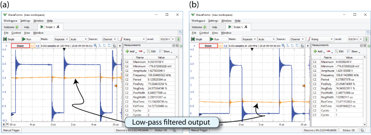
Figure 15-10: The PWM generator output: (a) 75% duty cycle (~2.5V) and (b) 25% duty cycle (0.8V)
The same example is built using C code in Listing 15-12, and the code is perhaps easier to follow.
Listing 15-12: /exploringbb/chp15/pru/pwmC/pwmC.c
#include <stdint.h>#include <pru_cfg.h>#include "resource_table_empty.h"// Delay factor which defines the PWM frequency#define DELAYFACTOR 10volatile register uint32_t __R30;volatile register uint32_t __R31;void main(void) {volatile uint32_t gpio, button;uint32_t percent, count;// The PWM percentage (0-100) for the positive cyclepercent = 75;// Use pru0_pru_r30_5 as an output i.e., 100000 or 0x0020gpio = 0x0020;// Use pru0_pru_r31_3 as a button i.e., 1000 or 0x0008button = 0x0008;// Stop the loop when the button is pressedwhile (!(__R31 && button)) {for(count=0; count<100; count++) {// Use two comparisons to equalize the timingif(count<=percent) { __R30 |= gpio; }if(count> percent) { __R30 &= (~gpio); }__delay_cycles(DELAYFACTOR);}}__halt();}
Interestingly, this example shows the challenges of writing code for the PRU in C while trying to maintain precise timing. For example, these lines of code:
if(count<=percent) { __R30 |= gpio; }if(count> percent) { __R30 &= (~gpio); }
would usually be written as this:
if(count<=percent) { __R30 |= gpio; }else { __R30 &= (~gpio); }
However, on testing the latter code, the timing is not consistent and results in a bias that is proportional to the duty cycle. By using two if() statements, the timing is balanced for the full range of duty cycles.
Figure 15-11 shows the PWM C program in operation, where the high-bandwidth oscilloscope is used to confirm the consistency observed in Figure 15-10.
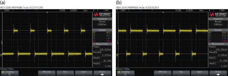
Figure 15-11: The PWM generator output with the PWM C program: (a) 25% duty cycle, (b) 75% duty cycle
A PRU Sine Wave Generator
The PRU PWM generator code in the previous section can be adapted to generate user-defined waveforms on a GPIO pin. This is achieved by altering the PWM signal duty cycle rapidly over time and passing the output through a low-pass filter. Figure 15-10 illustrates the output of such as circuit, where a 4.7 kΩ resistor and a 4.7 nF capacitor are used to form the requisite low-pass filter. The smoothing is effectively of shorter duration than the previous RC component values. Figure 15-12(a) displays the PWM signal with a duty cycle that changes over time. The low-pass filtered output is displayed in Figure 15-12(b), where it is clearly a good approximation to a sine waveform signal. The full project is available in the chp15/pru/sineWave/ directory.
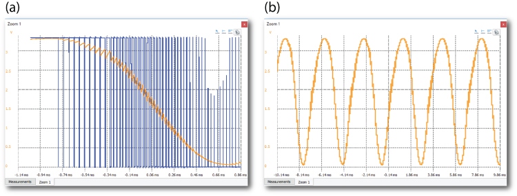
Figure 15-12: User-defined sine waveform output at different time bases: (a) with PWM signal present, and (b) low-pass output only
The PRU C code is provided in Listing 15-13. The main novelty in this code is the generation of a set of 100 values representing a single cycle of a sine waveform. The values of the sine wave cycle are designed to have an amplitude of 50 and an offset of +50 so that the output can be directly used as the duty cycle percentage values for the PWM generator code described in the previous section.
Listing 15-13: /exploringbb/chp15/pru/sineWave/sineWave.c
#include <stdint.h>#include <pru_cfg.h>#include "resource_table_empty.h"#include <math.h>// Delay factor which defines the PWM frequency#define DELAYFACTOR 0volatile register uint32_t __R30;volatile register uint32_t __R31;void main(void) {volatile uint32_t gpio, button;uint32_t count, i;uint32_t waveform[100];float gain = 50.0f; // want the full range 0-99float phase = 0.0f; // phase can be changedfloat bias = 50.0f; // center on 1.65V, full rangefloat freq = 2.0f * 3.14159f / 100.0f;for (i=0; i<100; i++){ // general sine wave equationwaveform[i] = (unsigned int)(bias + (gain * sin((i * freq) + phase)));}// Use pru0_pru_r30_5 as an output i.e., 100000 or 0x0020gpio = 0x0020;// Use pru0_pru_r31_3 as a button i.e., 1000 or 0x0008button = 0x0008;// Stop the loop when the button is pressedwhile (!(__R31 && button)) {for(i=0; i<100; i++){for(count=0; count<100; count++){// Use two comparisons to equalize the timingif(count<=waveform[i]) { __R30 |= gpio; }if(count> waveform[i]) { __R30 &= (~gpio); }__delay_cycles(DELAYFACTOR);}}}__halt();}
The PRU code in Listing 15-13 builds on the PWM code in Listing 15-12. The main difference is an additional loop that loads a PWM duty cycle for each data array value. The code will output any periodic waveform that is passed to it, with a maximum periodic sample length of just under 8 KB (PRU0 RAM0) in this example. The code could be improved to extend this limit or to iterate with fewer instructions. However, the code demonstrates the principle that a PRU can be used to generate arbitrary custom analog waveforms using its digital GPIO outputs.
An Ultrasonic Sensor Application
As described in Chapter 10, the HC-SR04 is a low-cost (~$5) ultrasonic sensor that can be used to determine the distance to an obstacle using the speed of sound. The sensor has a range of approximately 1″ (2.5 cm) to 13′ (4 m). It is a 5 V sensor, so logic-level translation circuitry is required (as described at the end of Chapter 8). The final circuit is illustrated in Figure 15-13. It uses the same pin configuration that is described earlier in this chapter.
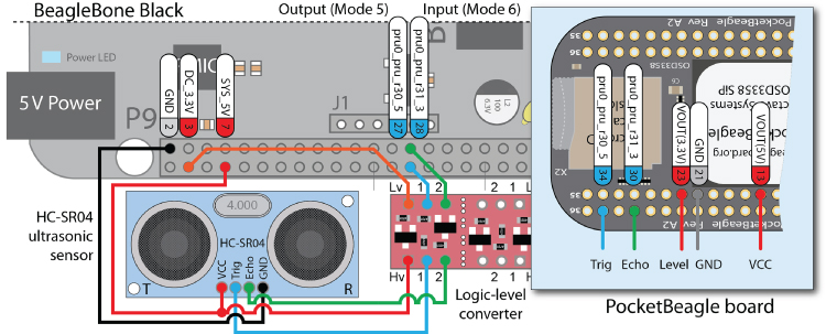
Figure 15-13: The HC-SR04 ultrasonic distance sensor circuit
Figure 15-14 illustrates how interaction takes place with this sensor. A 10 µs trigger pulse is sent to the “Trig” input of the sensor; the sensor then responds on its “Echo” output with a pulse that has a width that corresponds to the distance of an obstacle (approximately 150 µs to 25 ms, or 38 ms if no obstacle is in range).
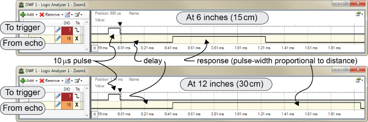
Figure 15-14: Signal response of the HC-SR04
The nondeterministic nature of Linux means that it would be difficult to use this sensor directly from Linux user space using regular GPIOs. There are UART versions of this sensor that contain a microcontroller, but they are much more expensive. In fact, the solution that is presented here is fast enough to enable you to connect ten or more such sensors to a single PRU—a single trigger signal could be sent to many sensors simultaneously, and different enhanced GPIOs could be used to measure the response signals from each sensor. Assembly language code is developed for this application with the following structure:
- Initialization takes place to set up shared memory.
- The main loop begins.
- A pulse is sent to the output pin. The output pin (P9_27/P2.34) is set high, and the code delays for exactly 10 μs before switching low.
- The input pin (P9_28/P2.30) is then polled until it goes high. At that point, a “width” timer counts until the input pin goes low.
- The width timer value is written into shared memory. The main loop begins again.
The project code is available in the directory /chp15/pru/ultrasonic/.
#include <stdint.h>#include <pru_cfg.h>#include <pru_ctrl.h>#include "resource_table_empty.h"#define PRU0_DRAM 0x00000000volatile unsigned int *shared = (unsigned int *)(PRU0_DRAM);extern void START(void);void main(void) {// The number of samplesshared[0] = 5000;// Sample delay in msshared[1] = 2;START();}
The PRU code is provided in Listing 15-15. The program loops as described and stores the current value in memory on each iteration.
Listing 15-15: /exploringbb/chp15/pru/ultrasonic/ultrasonic.asm
; Written for Exploring BeagleBone v2 by Derek Molloy; This program uses the PRU as an ultrasonic controller based on the; values in 0x00000000 (percentage) and 0x00000004 (delay).cdecls "main.c".clink.global START.asg 32, PRU0_R31_VEC_VALID ; allows notification of program completion.asg 3, PRU_EVTOUT_0 ; the event number that is sent back.asg 1000, TRIGGER_COUNT ;.asg 100000, SAMPLE_DELAY_1MS; Using register 0 for all temporary storage (reused multiple times)START:; Read number of samples to read and inter-sample delayLDI32 r0, 0x00000000 ; load the memory location, number of samplesLBBO &r1, r0, 0, 4 ; load the value into memory - keep r1; Read the sample delayLDI32 r0, 0x00000004 ; the sample delay is in the second 32-bitsLBBO &r2, r0, 0, 4 ; the sample delay is stored in r2MAINLOOP:LDI32 r0, TRIGGER_COUNT ; store length of the trigger pulse delaySET r30, r30.t5 ; set the trigger highTRIGGERING: ; delay for 10usSUB r0, r0, 1 ; decrement loop counterQBNE TRIGGERING, r0, 0 ; repeat loop unless zeroCLR r30, r30.t5 ; 10us over, set the triger low - pulse sent; clear the counter and wait until the echo goes highLDI32 r3, 0 ; r3 will store the echo pulse widthWBS r31, 3 ; wait until the echo goes high; start counting (measuring echo pulse width) until the echo goes lowCOUNTING:ADD r3, r3, 1 ; increment the counter by 1QBBS COUNTING, r31, 3 ; loop if the echo is still high; at this point the echo is now low - write the value to shared memoryLDI32 r0, 0x00000008 ; going to write the result to this addressSBBO &r3, r0, 0, 4 ; store the count at this address; one more sample iteration has taken placeSUB r1, r1, 1 ; take 1 away from the number of iterationsMOV r0, r2 ; need a delay between samplesSAMPLEDELAY: ; do this loop r2 times (1ms delay each time)SUB r0, r0, 1 ; decrement counter by 1LDI32 r4, SAMPLE_DELAY_1MS ; load 1ms delay into r4DELAY1MS:SUB r4, r4, 1QBNE DELAY1MS, r4, 0 ; keep going until 1ms has elapsedQBNE SAMPLEDELAY, r0, 0 ; repeat loop unless zeroQBNE MAINLOOP, r1, 0 ; loop if the no of iterations has not passedEND: ; end of program, send back interruptLDI32 R31, (PRU0_R31_VEC_VALID|PRU_EVTOUT_0)HALT ; halt the pru program
The C code in Listing 15-16 is a separate Linux userspace program that accesses the PRU memory location 0x4a30 0008 and reads the current timing value. It then uses the displayDistance() function to convert this value into its equivalent distance in inches and centimeters.
Listing 15-16: /exploringbb/chp15/pru/ultrasonic/readDistance.c
#include <stdio.h>…#include <sys/mman.h>#define MAP_SIZE 4096UL#define MAP_MASK (MAP_SIZE - 1)void displayDistance(unsigned int raw_distance) {float distin = ((float)raw_distance / (100 * 148));float distcm = ((float)raw_distance / (100 * 58));printf("Distance is %f inches (%f cm) ", distin, distcm);}int main(int argc, char **argv) {int fd, i, j;void *map_base, *virt_addr;unsigned long read_result, writeval;unsigned int numberOutputSamples = 1;off_t target = 0x4a300008;if((fd = open("/dev/mem", O_RDWR | O_SYNC)) == -1){printf("Failed to open memory! ");return -1;}fflush(stdout);map_base = mmap(0, MAP_SIZE, PROT_READ | PROT_WRITE, MAP_SHARED,fd, target& ~MAP_MASK);if(map_base == (void *) -1) {printf("Failed to map base address ");return -1;}fflush(stdout);for(j=0; j<1000; j++){for(i=0; i<numberOutputSamples; i++){virt_addr = map_base + (target & MAP_MASK);read_result = *((unsigned long *) virt_addr);//printf("Value at address 0x%X is: 0x%X ", target, read_result);displayDistance((unsigned int)read_result);usleep(500000);}fflush(stdout);}if(munmap(map_base, MAP_SIZE) == -1) {printf("Failed to unmap memory");return -1;}close(fd);return 0;}
The code example can be built using the build script and results in the following output when executed:
debian@ebb:~/exploringbb/chp15/pru/ultrasonic$ makedebian@ebb:~/exploringbb/chp15/pru/ultrasonic$ sudo make install_PRU0debian@ebb:~/exploringbb/chp15/pru/ultrasonic$ sudo ./readDistanceDistance is 5.335135 inches (13.551244 cm)
The program output updates on a single shell console line whenever it is sampled. This continues until the program is exited. The signal output is displayed in Figure 15-15. The sampling rate is variable in this example. It could be altered to a fixed sample period if required; however, a fixed sampling rate would have to account for the 38 ms pulse that the sensor returns when no obstacle is detected.
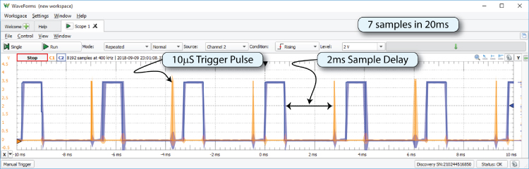
Figure 15-15: Signal response of the HC-SR04 with the ultrasonic project example
Summary
After completing this chapter, you should be able to do the following:
- Describe real-time kernel and hardware solutions that can be used on the Beagle boards
- Use tools such as the PRU Debugger and Texas Instruments' PRU Code Generation Tools (CGT) for PRU-ICSS application development
- Write a PRU program that can flash an LED and transfer it to the PRU-ICSS using remoteproc
- Describe the important features of the PRU-ICSS, such as its structure, registers, memory addressing, and assembly language instructions
- Write a PRU program that shares memory with a Linux host application
- Write a PRU program that interfaces to regular GPIOs that are in Linux host space
- Write a PRU program that generates PWM signals and adapts it to output user-defined analog waveforms on a GPIO pin
- Apply the PRU to sensor interfacing applications for which time measurement is important, such as interfacing to ultrasonic distance sensors
Further Reading
There are many links to websites and documents provided throughout this chapter. Additional links and further information on the topics in this chapter are provided at www.exploringbeaglebone.com/chapter15/.
Prof. Mark A. Yoder, co-author of the BeagleBone Cookbook, has developed a PRU Cookbook, which is an excellent resource for those who are planning to develop PRU applications. See markayoder.github.io/PRUCookbook/.
Mark A.Yoder, Jason Kridner, BeagleBone Cookbook: Software and Hardware Problems and Solutions, O'Reilly Media Inc., ISBN: 1491905395, 2015.