
CHAPTER 6
Interfacing to the Beagle Board Input/Outputs
This chapter integrates the Linux, programming, and electronics groundwork from earlier chapters to show you how to build circuits and write programs that interface to Beagle board single-wire inputs and outputs. In this chapter, you will see practical examples that explain how to use a general-purpose input/output (GPIO) to output a binary signal to switch on an LED or to read in a binary input from a push button. Optocoupler circuits are discussed so that you can safely interface to externally powered circuits. Also included are the steps required to read in an analog input and to send out a pulse-width modulated (PWM) output. GPIO interfacing is first performed using sysfs to ensure that you have skills that are transferrable to other embedded Linux devices. Next, BoneScript and memory-mapped approaches are investigated, which are largely specific to the AM335x SoC. Finally, there is a brief discussion on the impact of udev rules and Linux permissions on GPIO interfacing.
EQUIPMENT REQUIRED FOR THIS CHAPTER:
- BeagleBone or PocketBeagle SBC
- General components from Chapter 4 and a generic light-dependent resistor
- Hitec HS-422 Servo Motor (or equivalent)
Further details on this chapter are available at www.exploringbeaglebone.com/chapter6/.
General-Purpose Input/Outputs
At this point in the book, you have seen how to administrate a Linux system, write high-level programming code, and build basic but realistic electronic interfacing circuits. It is now time to bring those different concepts together so that you can build software applications that run on Linux to control, or take input from, electronics circuits of your own design.
Introduction to GPIO Interfacing
It is possible to interface electronic circuits and modules to the Beagle boards in several different ways. Here are some examples:
- Using the GPIOs on the expansion headers: This provides you with versatility in terms of the type of circuits that you can connect and is the subject of this chapter.
- Using the buses (e.g., I2C, SPI, CAN Bus), or UARTs on the expansion headers: Bus connections enable communications to complex modules such as sensors and displays. This topic is discussed in Chapter 8.
- Connecting USB modules (e.g., keyboards, Wi-Fi): If Linux drivers are available, many different electronic device types can be connected to a Beagle board. Examples are provided throughout later chapters.
- Communicating through Ethernet/Wi-Fi/Bluetooth/ZigBee to electronics modules: It is possible to build network-attached sensors that communicate to the Beagle boards using network connections. Chapter 11 and Chapter 12 focus on this topic.
The next step in working with a Beagle board is to connect it to circuits using the GPIOs and analog inputs of the expansion headers (as illustrated in Figure 1-5 and Figure 1-6 of Chapter 1). The background material of earlier chapters is important, as this is a surprisingly complex topic that will take some time to get used to, particularly the content on the Linux device tree and pin multiplexing. However, code and example circuits are provided throughout this chapter that you can use to help you build your own circuits.
Figure 6-1 provides you with a first view of the functionality of the inputs and outputs on the BeagleBone's P8 and P9 headers. Many of these pins are multiplexed, meaning they have many more functions than what is displayed in the figure. The name listed typically describes the default operation of the pin. An equivalent figure is provided for the PocketBeagle P1 and P2 headers in Figure 6-2.
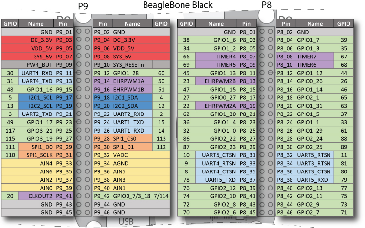
Figure 6-1: The BeagleBone P8/P9 headers with pin names, which describe each pin's default functionality
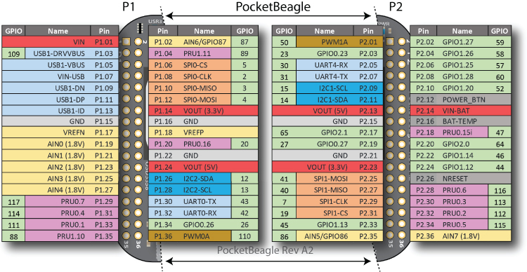
Figure 6-2: The PocketBeagle P1/P2 headers with pin names, which describe each pin's default functionality
This chapter discusses how you can interface to the expansion header pins in the following ways:
- Digital output: How you can use a GPIO to turn an electrical circuit on or off. The example uses an LED, but the principles hold true for any circuit type; for example, you could even use a relay to turn on/off high-powered devices. A circuit is provided to ensure that you do not draw too much current from a GPIO. A C++ class is developed to make software interfacing straightforward and efficient.
- Digital input: How you can read in a digital output from an electrical circuit into a software application running under Linux. Circuits are provided to ensure that this is performed safely for your board. At the end of the chapter, more advanced digital input that allows for efficient detection of an input state change is also discussed.
- Analog input: How you can read in an analog output from an electrical circuit in the range of 0 V to 1.8 V (or 3.3 V on selected PocketBeagle pins) using one of the Beagle board's on-board analog-to-digital converters (ADCs). A circuit is provided to ensure that you do not draw current from the reference supply, which would mean that its voltage value could no longer be guaranteed.
- Analog output: How you can use PWM to output a proportional signal that can be used as an analog voltage level or as a control signal for certain types of devices, such as servo motors.
This chapter assumes you have read Chapter 4—in particular, switching circuits using FETs and the use of pull-up/down resistors.
GPIO Digital Output
The example output configuration illustrated in Figure 6-3 uses a GPIO connected to a FET to switch a circuit using the same GPIO on a BeagleBone and a PocketBeagle board. As described in Chapter 4, when a voltage is applied to the gate input of a FET, it will close the virtual drain-source “switch,” enabling current to flow from the 5 V supply through the 220 Ω current-limiting resistor and then to GND through a lighting LED. The advantage of this type of circuit is that it can be applied to many on/off digital output applications, as the BS270 FET data sheet indicates that it can drive a constant current of up to 400mA (and a pulsed current of up to 2A) across the drain-source at up to 60V. However, the maximum current is limited in this circuit, not by the FET, because the SYS_5V/VOUT(5V) pin (P9_07/P2.13) can supply a maximum of 250mA. As an alternative on the BeagleBone, the VDD_5V (P9_05 and P9_06) can supply up to 1A, but it is active only if a power supply is plugged into the 5V DC jack.
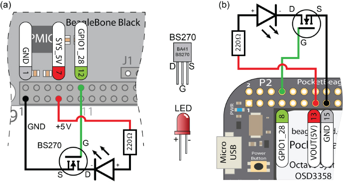
Figure 6-3: A FET-driven LED circuit connected to GPIO 60 on (a) the BeagleBone and (b) the PocketBeagle
Beagle board GPIOs are 3.3V tolerant, and you can only source 4–6 mA and sink about 8mA to each pin. In the example, it is safe to use the 5V supply to drive the LED, as the drain source circuit of the FET is never connected to the gate input. You will also notice that, unlike the example in Chapter 4, there is no resistor on the gate of the FET. It is not necessary in this particular case because an internal pull-down resistor is enabled within the BeagleBone or PocketBeagle, by default, on this pin. This is discussed shortly.
As described in Figure 6-1 and Figure 6-2, the P9 header pin on the BeagleBone and the P2 on the PocketBeagle have different GPIOs available. GPIO1_28 is available on P9 pin 12 on the BeagleBone and on P2 pin 8 on the PocketBeagle. Once the circuit is built and attached to the Beagle board, you can boot the board and control the LED using a Linux terminal.
The AM335x has four banks (0–3) of 32 GPIOs that are numbered 0 to 31. This means that GPIO1_28 is GPIO 28 of 32 (0–31) on the second GPIO chip of four (0–3). As there are 32 GPIOs on each GPIO chip, the internal GPIO number corresponding to pin GPIO1_28 is calculated as follows: (1×32) + 28 = 60. The total range is GPIO 0 (i.e., GPIO0_0) to GPIO 127 (i.e., GPIO3_31), but as previously discussed, not all AM335x GPIOs are available on the headers of the different Beagle boards.
GPIOs on the BeagleBone P8 header or the PocketBeagle P1 header can also be used, but to keep the figures concise, the P9 header GPIOs on the BeagleBone and P2 header on the PocketBeagle are chosen. To use GPIO 60 as an output, use the following commands at the Linux shell prompt on the PocketBeagle p2.08 (substitute in p9.12 for the BeagleBone):
debian@ebb:~$ config-pin -a p2.08 outdebian@ebb:~$ config-pin -q p2.08P2_08 Mode: gpio Direction: out Value: 0
The query result indicates that the pin is now set up as a GPIO in output mode.
You can then browse to the relevant GPIO sysfs directory so that you can control the pin directly. The /sys/class/gpio/ directory lists the available GPIOs along with the four GPIO banks (labeled 0, 32, 64, and 96).
debian@ebb:~$ cd /sys/class/gpio/debian@ebb:/sys/class/gpio$ lsexport gpio117 gpio23 gpio41 gpio50 gpio7 gpiochip96gpio110 gpio12 gpio26 gpio42 gpio52 gpio86 unexportgpio111 gpio13 gpio27 gpio43 gpio57 gpio87gpio112 gpio14 gpio3 gpio44 gpio58 gpio88gpio113 gpio15 gpio30 gpio45 gpio59 gpio89gpio114 gpio19 gpio31 gpio46 gpio60 gpiochip0gpio115 gpio2 gpio4 gpio47 gpio64 gpiochip32gpio116 gpio20 gpio40 gpio5 gpio65 gpiochip64
You can see all the GPIOs that are currently available on the PocketBeagle board. GPIOs that are not available are being utilized for other functions (see Figure 6-2) or have not been physically connected to the headers.
debian@ebb:/sys/class/gpio$ cd gpio60debian@ebb:/sys/class/gpio/gpio60$ ls -ltotal 0-rw-rw-r-- 1 root gpio 4096 Jan 1 2000 active_lowlrwxrwxrwx 1 root gpio 0 May 17 03:25 device -> …-rw-rw-r-- 1 root gpio 4096 Jan 1 2000 direction-rw-rw-r-- 1 root gpio 4096 Jan 1 2000 edge-rw-rw-r-- 1 root gpio 4096 Jan 1 2000 labeldrwxrwxr-x 2 root gpio 0 Jan 1 2000 powerlrwxrwxrwx 1 root gpio 0 May 17 03:25 subsystem -> …-rw-rw-r-- 1 root gpio 4096 Jan 1 2000 uevent-rw-rw-r-- 1 root gpio 4096 Jan 1 2000 valuedebian@ebb:/sys/class/gpio/gpio60$ cat labelP2_08debian@ebb:/sys/class/gpio/gpio60$ cat directionout
The GPIO is confirmed as an output, and the value can be changed, which results in the LED connected to GPIO1_28 (as in Figure 6-3) being turned on and off.
debian@ebb:/sys/class/gpio/gpio60$ echo 1 > valuedebian@ebb:/sys/class/gpio/gpio60$ echo 0 > value
To test the performance of this approach, a short script to flash the LED as quickly as possible, using a bash shell script, follows. This does not result in a visible “blink,” as the LED is flashing faster than can be visibly observed; however, it can be visualized using an oscilloscope.
debian@ebb:~/exploringbb/chp06/flash_script$ more flash.sh#!/bin/bash# Short script to toggle a GPIO pin at the highest frequency# possible using Bash - by Derek Molloyecho "out" > /sys/class/gpio/gpio60/directionCOUNTER=0while [ $COUNTER -lt 100000 ]; doecho 0 > /sys/class/gpio/gpio60/valueecho 1 > /sys/class/gpio/gpio60/valuelet COUNTER=COUNTER+1donedebian@ebb:~/exploringbb/chp06/flash_script$ ./flash.sh
You can see from the oscilloscope trace in Figure 6-5 that the output is cycling every 0.54 ms approximately (although not all cycles are the same length), equating to a frequency of approximately 1.86 kHz, which is not very high for an embedded controller. In addition, the top command (executed in another Linux terminal window) indicates that the CPU load for this script is 98 percent. If you attach a multimeter, you can also see that the current driving the LED is 12 mA, which is large enough to damage a Beagle board if this current were directly sourced from, or sinked to, a GPIO itself.
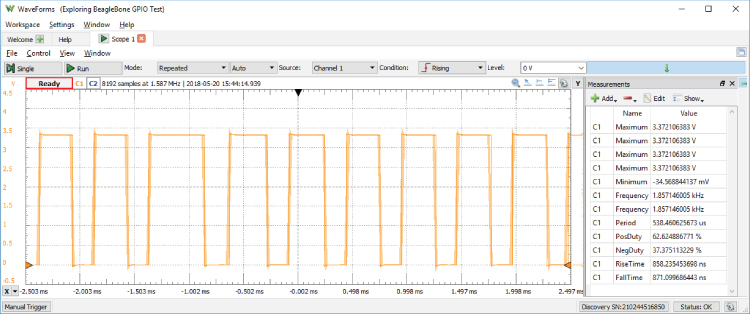
Figure 6-5: Scope output measuring the maximum switching rate for a GPIO controlled with the flash.sh script
A C++ class is presented later in this chapter that can be used to control a GPIO, and it achieves higher switching frequencies but with similar CPU loads. If you require a high-frequency periodic switching signal, then PWM, which is discussed later in this chapter, can be used. PWM can achieve frequencies of 1 MHz or higher, without a significant CPU load. If you require a non-periodic output at a high frequency, then you will have to investigate the Programmable Real-Time Units (PRUs) in Chapter 15. However, many applications require the activation of a switched circuit at low frequencies (e.g., controlling motors, smart home control, etc.), and in such cases this configuration is perfectly valid.
GPIO Digital Input
The next application uses a GPIO as a digital input, which will enable software written on the board to read the state of a push button or any other logic high/low input. This task is first performed using a Linux terminal, and then it is performed using C/C++ code. The LED circuit in Figure 6-3 can be left connected when building this circuit.
The circuit shown in Figure 6-6 uses a normally open push button (SPST) that is connected to the GPIO1_14, which is pin 16 on the BeagleBone P8 header or pin 22 on the PocketBeagle P2 header. You will notice that, having discussed the need for pull-up or pull-down resistors on push button switches in Chapter 4, none are present in this circuit. This is not accidental, as we have control over internal pull-up and pull-down resistors on the Beagle boards using the config-pin tool.
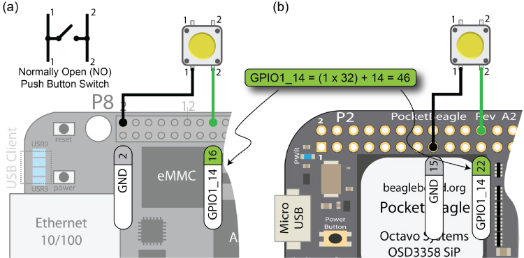
Figure 6-6: A GPIO button input example with an internal pull-up resistor enabled on (a) the BeagleBone and (b) the PocketBeagle
In this example, say you want to configure the button to have a pull-up resistor enabled on the input pin. This means that the input will be high (pulled up to 3.3V through the internal resistor) when the button is not pressed, and it will be low (connected to GND through the button) when the button is pressed. You can set this configuration on the PocketBeagle as follows, where you configure pin 22 on the P2 header as a GPIO input (in) with a pull-up resistor (+) (use p8.16 in place of p2.22 on the BeagleBone board):
debian@ebb:~$ config-pin -q p2.22P2_22 Mode: default Direction: in Value: 0debian@ebb:~$ config-pin -a p2.22 in+debian@ebb:~$ config-pin -q p2.22P2_22 Mode: gpio_pu Direction: in Value: 1
The query (-q) output on the last line indicates that the GPIO is an input in pull-up mode (i.e., gpio_pu) and that the present input value is high (1).
You can use sysfs to read the state of the button using a Linux terminal, where GPIO1_14 is GPIO 46 (i.e., (1 × 32) + 14):
debian@ebb:~$ cd /sys/class/gpio/gpio46debian@ebb:/sys/class/gpio/gpio46$ ls -l-rw-rw-r-- 1 root gpio 4096 Jan 1 2000 active_lowlrwxrwxrwx 1 root gpio 0 May 17 03:25 device -> …-rw-rw-r-- 1 root gpio 4096 May 20 17:09 direction-rw-rw-r-- 1 root gpio 4096 Jan 1 2000 edge-rw-rw-r-- 1 root gpio 4096 Jan 1 2000 labeldrwxrwxr-x 2 root gpio 0 Jan 1 2000 powerlrwxrwxrwx 1 root gpio 0 May 17 03:25 subsystem -> …-rw-rw-r-- 1 root gpio 4096 Jan 1 2000 uevent-rw-rw-r-- 1 root gpio 4096 Jan 1 2000 valuedebian@ebb:/sys/class/gpio/gpio46$ cat directionindebian@ebb:/sys/class/gpio/gpio46$ cat value1
And, when the button is pressed, and subsequently released, you'll see this:
debian@ebb:/sys/class/gpio/gpio46$ cat value0debian@ebb:/sys/class/gpio/gpio46$ cat value1
To reiterate, since there is an internal pull-up resistor enabled on the input, it is “pulled up” to 3.3 V when no input is attached. This means that the button input value is 1 when the button is not pressed. When the button is pressed, the input is grounded and a 0 value is read when it is pressed. Each time you type cat value, you are polling the input to check the value. The downside of this approach is that you will not identify a change in the value of the input unless you constantly poll the value state.
Interestingly, if you reconfigure p2.22 to have a pull-down resistor (-) instead of a pull-up resistor using the following:
debian@ebb:/sys/class/gpio/gpio46$ config-pin -a p2.22 in-debian@ebb:/sys/class/gpio/gpio46$ cat value0debian@ebb:/sys/class/gpio/gpio46$ cat value0
you will see that the input value is always 0 whether the button is pressed or released. That is because this input is connected via an internal pull-down resistor to ground, meaning that the input is connected to ground in either case. It should be clear at this stage that you need to understand the GPIO configuration, including these internal resistors, to use the GPIO pins properly.
GPIO Configuration
The importance of pull-up and pull-down resistors is discussed in some detail in Chapter 4. They ensure that open switches do not allow a GPIO input to float. Such external resistors are typically “strong” pull-up/down resistors in that they “strongly” tie the input to a high/low value using relatively low resistance values (e.g., 5-10 k Ω).
Internal Pull-Up and Pull-Down Resistors
The Beagle boards have “weak” internal pull-up and internal pull-down resistors that can be configured by setting internal registers in the AM335x SoC. You can physically check whether an internal pull-up or pull-down resistor is enabled on a pin by connecting a 100kΩ resistor between the pin and GND (as shown in Figure 6-7(a), where the shaded area represents functionality that is internal to the AM335x) and then between the pin and the 3.3V supply (as shown in Figure 6-7(b)). If you connect a 100kΩ (the one I used had an actual value of 98.6kΩ) to P8_12 and measure the voltage across it, you will see that the voltage drop is 0V when the resistor is connected to GND, and I measured 2.739V (not 3.3V) when it was connected to the 3.3V rail. This indicates that there is an internal pull-down resistor enabled, and the combination of these resistors is behaving like a voltage divider circuit. You can even estimate the value of the internal pull-down resistor as in Figure 6-7(b).
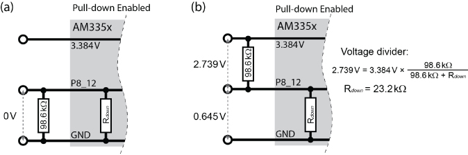
Figure 6-7: Internal BeagleBone pull-down resistor example, with an external resistor connected (a) from the pin to GND, and (b) from the pin to the 3.3V supply
Clearly, P8_12, which is GPIO1_12, has an internal pull-down resistor enabled in this case, but if you perform the same test on P8_26, which is GPIO1_29, you should get a completely different response. When you connect the resistor as shown in Figure 6-7(a), you will get a voltage drop of ~2.624V across the 100kΩ resistor, and almost 0V (~0.162V) when you connect it as in Figure 6-7(b). That is because P8_26 has an internal pull-up resistor enabled by default. Performing the same calculations gives an internal pull-up resistor value of about 28.6kΩ.
You need to factor these resistor values into the behavior of your input/output circuits, and you need to be able to alter the internal resistor configuration in certain circumstances.
GPIO Pin Configuration Settings
As well as configuring pins to have either a pull-up or a pull-down resistor configuration, there are seven different modes for each pin. This is called the multiplexer mode (mmode) for the pin, and it is set using a three-digit binary number, as described in the first row of Table 6-1. This table is based on information provided in the AM335x TRM (GPIOs conf_<module>_<pin> - Table 9-60 of the TRM). Using these bit settings, you can construct a seven-bit value that can be used to configure the exact behavior of a GPIO pin within Linux using device tree overlays, which is discussed shortly.
Table 6-1: GPIO Pin User-Configuration Settings
| BIT | AM335X FIELD | DESCRIPTION |
| 0,1,2 |
mmode
|
The multiplexer mode: Using the three least-significant bits you can select a mode between 0 and 7, e.g., 000=0, 111=7. This enables each pin to have up to eight different modes. |
| 3 |
puden
|
Enable internal pull-up/pull-down resistor: Enable=0, Disable=1. |
| 4 |
putypesel
|
Select internal pull-up or pull-down form: Pull-down=0, Pull-up=1. |
| 5 |
rxactive
|
Input Active: Receiver disabled=0, Input enabled=1. If this bit is set high, the pin will be an input; otherwise, it will be an output. |
| 6 |
slewctrl
|
Slew Control: Fast=0, Slow=1. Slew rate provides control over the rise/fall time of an output. You would set this value to slow only if you were using long interconnects, such as on I2C buses. |
The mmode is discussed shortly, but when working with GPIOs, the mmode will be 7, and therefore the most common hexadecimal values that are used to configure a GPIO's settings are as follows (bit 6 is the most significant bit [MSB] and is on the LHS):
0x27(0100111) Fast, Input, Pull-Down, Enabled and Mux Mode 70x37(0110111) Fast, Input, Pull-Up, Enabled, Mux Mode 70x07(0000111) Fast, Output, Pull-down, Enabled, Mux Mode 70x17(0010111) Fast, Output, Pull-up, Enabled, Mux Mode 70x2F(0101111) Fast, Input, Pull-down, Disabled, Mux Mode 7
These configuration values are useful, as they enable you to set the pins into the exact operational mode that you require. The tables shown in Figures 6-8 and 6-9 provide the most important information required when interfacing to AM335x-based Beagle boards. They have been generated using the SRM, the AM335x TRM, and information that can be gleaned from the Debian Linux distribution. The figures illustrate the mmode options that are available on each of the BeagleBone's P8 and P9 headers and the PocketBeagle's P1 and P2 headers. They are available in PDF form in the GitHub repository (chp06/headers/) so that they can be displayed on your computer in color and printed as required.
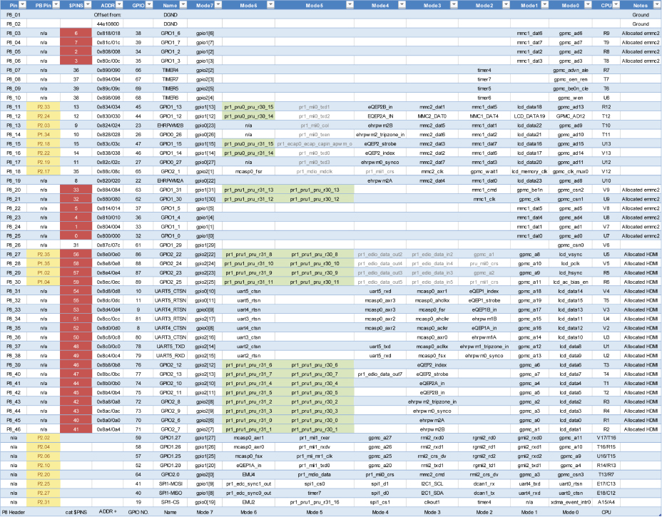
Figure 6-8: The P8 header pins and equivalent PocketBeagle (PB) pins
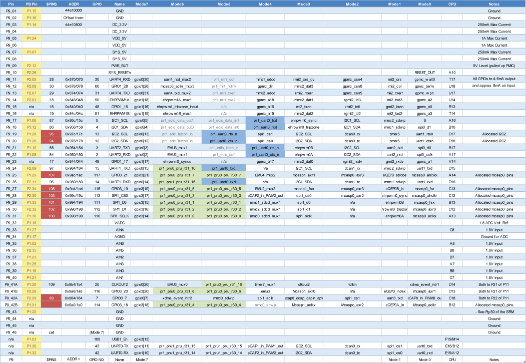
Figure 6-9: The P9 header pins and equivalent PocketBeagle (PB) pins
Quite a large amount of information is presented in these two tables, and subsequent chapters in the book will frequently refer to them. For the moment, note a few points that are particularly important:
- Any pin that is highlighted in the $PINS column is already allocated and should not be used unless you disable the functionality that it is allocated to (e.g., the HDMI output or the eMMC). See the Notes column for further details.
- Mode7 is the GPIO
mmode. - As discussed, the GPIO number is calculated by taking the GPIO chip number, multiplying it by 32, and then adding the offset. For example, GPIO1_12 = (1 × 32) + 12 = GPIO 44.
- The $PINS number is not the GPIO number. This $PINS number in the table is a software reference for each of the pins, and these values are provided in the second column of the table.
- Highlighted items in the Mode6 and Mode5 columns relate to PRU functionality, discussed in Chapter 15.
The header pins P9_12/P2_08 (used for output) and P8_16/P2_22 (used for input) can be used as an illustration of the information in these tables. These are the pins that were physically tested as described earlier. If you examine Figure 6-8, you will see under P8_12 and P8_26 the following values:
Head $PINS ADDR/OFFSET GPIO Name Mode7P9_12 30 0x878/078 60 GPIO1_28 gpio1[28] …P8_16 14 0x838/038 46 GPIO1_14 gpio1[14] …
This information is consistent with the output of the show-pins.pl script when executed on the PocketBeagle.
debian@ebb:~$ cd /opt/scripts/device/debian@ebb:/opt/scripts/device$ lsblue bone x15debian@ebb:/opt/scripts/device$ cd bonedebian@ebb:/opt/scripts/device/bone$ perl show-pins.pl | grep 1.28P9.12 30 U18 fast rx down 7 gpio 1.28ocp/P2_08_pinmux (pinmux_P2_08_default_pin)debian@ebb:/opt/scripts/device/bone$ perl show-pins.pl | grep 1.14P8.16 14 V13 fast rx down 7 gpio 1.14ocp/P2_22_pinmux (pinmux_P2_22_default_pin)
You can see that the P8_16/P2_22 pin has PINS number 14, physical pad number V13 on the AM335x, fast slew rate, input mode (rx), and a pull-down resistor enabled (down), and it is in GPIO mode 7 (7), which is GPIO1_14. This pin is mapped to pin 16 on the BeagleBone P8 header and pin 22 on the PocketBeagle P2 header.
The fact that the name of the pin is the same as its Mode7 value means that Mode7 is most likely enabled by default. You can test this in Linux as follows (you must use a superuser account):
debian@ebb:~$ sudo -iroot@ebb:~# cd /sys/kernel/debug/pinctrl/44e10800.pinmux/root@ebb:/sys/kernel/debug/pinctrl/44e10800.pinmux# lsgpio-ranges pingroups pinmux-functions pinmux-pins pinsroot@ebb:/sys/kernel/debug/pinctrl/44e10800.pinmux# cat pinsregistered pins: 142pin 0 (PIN0) 44e10800 00000027 pinctrl-single…pin 14 (PIN14) 44e10838 00000027 pinctrl-single…
The pin number is the $PINS value of the pin in question. Therefore, you can see that P8_16 ($PINS value 14) is in mode 0x27, which is an input in Mode7 (gpio1[14]) with a pull-up resistor enabled. Please note that these values will change as you use the config-pin tool.
You can actually query the value at the memory address itself using C code that accesses /dev/mem directly. Because P8_16 ($PINS14) is mapped at the memory address 44e10838 (see the ADDR column in Figure 6-8, or the preceding pins file), you can use the following steps to install Jan-Derk Bakker's devmem2 program (as mentioned in Chapter 3):
~$ wget http://www.lartmaker.nl/lartware/port/devmem2.c~$ gcc devmem2.c -o devmem2~$ sudo ./devmem2 0x44e10838/dev/mem opened.Memory mapped at address 0xb6fc6000.Value at address 0x44E10838 (0xb6fc6838): 0x27
The value 0x27 is expected for $PINS14. You can investigate the source code of devmem2 to see how it can be integrated into your projects.
Interfacing to Powered DC Circuits
The Beagle board itself provides the power required for the output and input circuits that are illustrated in Figures 6-3 and 6-6, respectively. The current that can be sourced or sinked by these circuits is limited by the particular board specifications. Therefore, it is often necessary to interface to circuits that are powered by an external supply.
You must be careful when interfacing your board to circuits that have their own power supply (e.g., high-powered LEDs, car alarms, garage openers). For example, you should design the circuit so that it does not attempt to source current from, or sink current to, the GPIOs while the board is powered off. In addition, it would be ideal if you could avoid sharing a GND connection between the circuit and the Beagle board in case that something should go wrong with the circuit or its power supply.
A good solution is to utilize low-cost optocouplers, such as those described in Chapter 4 to design circuits in which there is no electrical connection whatsoever between the Beagle board and the externally powered circuit. Figure 6-11 illustrates an output circuit with an NPN transistor that is placed in a Darlington pair arrangement with the optocoupler to switch on or off the externally powered circuit load. A 5V external power supply is used in this example, but a greater DC supply voltage can be used. In addition, the maximum switching current is limited by the transistor characteristics (e.g., of a BC547), not by the optocoupler's output current Ic level.
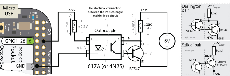
Figure 6-11: The optocoupler output circuit
The 617A optocoupler's current transfer ratio (CTR) of ≈0.5 when If = 1mA (i.e., when GPIO1_28 is high) results in an output current of Ic = 0.5mA, which enters the base of the BC547 transistor. This small current switches on the BC547 transistor, which in turn supplies a current of IL = 40mA to the resistive load in this example. One downside of this configuration is that the voltage supply to the load is reduced by the VCE of the Darlington pair (≈1V). An alternative to this arrangement is to use a Sziklai pair as illustrated in Figure 6-11, in which a PNP transistor is connected to the optocoupler output. Both arrangements limit the switching frequency capability of your output circuit (typically to the tens of kilohertz range). Unlike the 617A, the 4N25 exposes the base of the optocoupler receiver. This allows for the placement of additional base emitter resistors to improve the circuit's frequency response.
An optocoupler can also be connected to a GPIO to receive an input from an externally powered DC circuit, as illustrated in Figure 6-12. Importantly, this circuit can be adapted for any DC supply voltage, and it will not sink any current to the GPIO input when the board is powered off. You must choose a resistor value for the input side of the optocoupler to limit the forward current of the diode (If(max) < 60mA for the 617A/4N251).
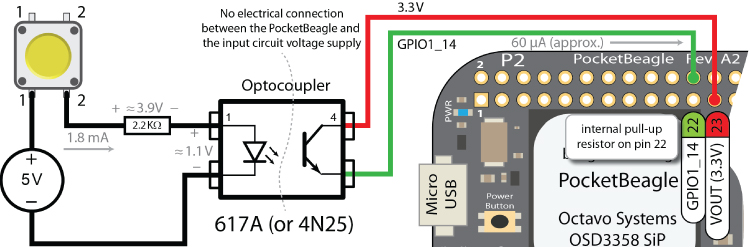
Figure 6-12: The optocoupler input circuit
GPIO1_14 can be configured to use an internal pull-down resistor by default, so it has a low state when the button is not pressed. The GPIO input circuit in Figure 6-12 sinks approximately 60μA to GPIO1_14 when the button is pressed. Similarly, this is the maximum current that will be sinked by this circuit (when If and Vf exceed minimal levels for the optocoupler). This circuit can be adapted to handle a varying DC input voltage (within a range) by using a voltage regulator to maintain a value of If that is less than If(max) for the chosen optocoupler.
C++ Control of GPIOs
A C++ class has been written for this book that wraps the GPIO functionality on the Beagle boards to make GPIOs easier to use. Listing 6-1 provides a segment of the class description that lists its basic I/O functionality. The more advanced functionality that has been removed from this code fragment is discussed at the end of this chapter. The implementation of this functionality is similar to the code that was written previously for the Beagle board LEDs. The full code listing is in /chp06/GPIO/GPIO.h and GPIO.cpp.
The C++ code is separated into header (.h) and implementation (.cpp) files, and the process of building applications in this form is called separate compilation. Separate compilation makes building large projects more efficient, but it can be difficult to manage all the files. The next chapter introduces the Eclipse integrated development environment (IDE) for cross-compilation, which can make this process seamless.
Listing 6-1: /chp06/GPIO/GPIO.h (Partial Listing)
// GPIO Class written by Derek Molloy (www.derekmolloy.ie)#include<string>#include<fstream>using std::string;using std::ofstream;#define GPIO_PATH "/sys/class/gpio/"namespace exploringBB { //All code is within a namespace// Enumerations are used to restrict the optionsenum GPIO_DIRECTION{ INPUT, OUTPUT };enum GPIO_VALUE { LOW=0, HIGH=1 };enum GPIO_EDGE { NONE, RISING, FALLING, BOTH };class GPIO {private:int number, debounceTime;string name, path;public:GPIO(int number); //constructor will export the pinvirtual int getNumber() { return number; }// General Input and Output Settingsvirtual int setDirection(GPIO_DIRECTION);virtual GPIO_DIRECTION getDirection();virtual int setValue(GPIO_VALUE);virtual int toggleOutput();virtual GPIO_VALUE getValue();virtual int setActiveLow(bool isLow=true); //low=1, high=0virtual int setActiveHigh(); //default//software debounce input (ms) - default 0virtual void setDebounceTime(int time){this->debounceTime = time;}// Advanced OUTPUT: Faster write using a stream (~20x)virtual int streamOpen();virtual int streamWrite(GPIO_VALUE);virtual int streamClose();// Advanced INPUT: presented at the end of this chaptervirtual ~GPIO(); //destructor will unexport the pinprivate: // Hidden functionalityint write(string path, string filename, string value);int write(string path, string filename, int value);string read(string path, string filename);ofstream stream;…};/* End of GPIO class */} /* namespace exploringBB */
You can extend this class through inheritance to add the functionality you require, and you can integrate it into your projects without restrictions on its use. Use of this class is demonstrated in the following short code example in Listing 6-2 that interacts with the LED and button circuits described earlier in this chapter:
Listing 6-2: /chp06/GPIO/simple.cpp
#include<iostream>#include<unistd.h> //for usleep#include"GPIO.h"using namespace exploringBB;using namespace std;int main(){GPIO outGPIO(60), inGPIO(46);// Basic Output - Flash the LED 10 times, once per secondoutGPIO.setDirection(OUTPUT);for (int i=0; i<10; i++){outGPIO.setValue(HIGH);usleep(500000); //micro-second sleep 0.5 secondsoutGPIO.setValue(LOW);usleep(500000);}// Basic Input exampleinGPIO.setDirection(INPUT);cout << "The value of the input is: "<< inGPIO.getValue() << endl;// Fast write to GPIO 1 million timesoutGPIO.streamOpen();for (int i=0; i<1000000; i++){outGPIO.streamWrite(HIGH);outGPIO.streamWrite(LOW);}outGPIO.streamClose();return 0;}
You can build and execute this code as follows:
…/chp06/GPIO$ g++ simple.cpp GPIO.cpp -o simple -pthread…/chp06/GPIO$ ./simpleThe value of the input is: 0
where you need to pass both .cpp files to the compiler, as due to separate compilation the source code is split over multiple files. The -pthread flag is required for class functionality that is described later in this chapter.
This code example flashes the LED 10 times, reads the state of the button, and then flashes the LED 1 million times (in about 25 seconds on a PocketBeagle). To test the performance of this structure, Figure 6-13 captures the signal output of the LED flashing in (a) when the setValue() method is used with no sleep call, and in (b) when the streamWrite() method is used. In (a) it is flashing at about 5.5 kHz, and in (b) it is flashing at about 125 kHz. Unfortunately, the C++ application had to run at 93 percent of CPU usage to generate these outputs, which is not really practical on a multiuser, multiprocess OS such as Linux, and it is certainly not very efficient.
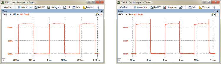
Figure 6-13: The C++ class flashing the LED
PWM is discussed later in this chapter, illustrating how to switch a GPIO using a regular periodic signal, at a fixed frequency, with negligible CPU load. For fast GPIO switching using a nonperiodic signal, the PRU-ICSS (see Chapter 15) would likely be required. An unsafe technique that uses direct access to system memory is also possible; and although it is definitely not recommended, it is explained next because of its value in learning about what is going on “under the hood.”
The Linux Device Tree
The first introduction to the Linux boot process is in Chapter 3, where it is made clear that Linux running on an embedded device, such as a Beagle board, does not have a BIOS. Rather, to boot and configure the device, it uses files on the SD card or eMMC that describe the machine's hardware. Every type of embedded Linux device has its own unique set of files to describe its platform hardware.
When the original Beagle boards were running older Linux kernels, the specific modifications required to those Linux kernels were applied to the Linux source code directly by using a file called board-am335xevm.c. The popularity of ARM-based microprocessors led to a proliferation of Linux kernel customizations. As a result, Linus Torvalds was unhappy with the amount of code that was being added directly to mainline Linux to describe each and every feature, for each and every ARM device being manufactured (the board-am335xevm.c has more than 4,000 lines of code). Therefore, new ARM boards using the latest Linux kernels use flattened device tree (FDT) models instead, a technology that has been used by PowerPC developers for many years.
The device tree was originally designed to be understood by humans in a readable form, which is then converted into an efficient machine-readable format. In 1994 it was formally specified as the IEEE Standard for Boot (Initialization Configuration) Firmware, which provides a standard for boot firmware requirements and practices—see tiny.cc/beagle604. It was utilized as early as 1995 in the PowerPC (Apple/Motorola) and by Sun Microsystems as a tree structure to describe hardware. Given the proliferation of ARM devices, it made sense for developers to revisit the device tree, and today more than 1,000 ARM-based boards are now using the device tree model. Until recently the device tree model was implemented only at the Linux kernel boot stage.
The U-Boot second-stage bootloader was introduced in Chapter 3, and an example output is presented that results from a board being booted. In recent years, U-Boot has been developed to support the device tree model so as to avoid hard-coding hardware topology into U-boot. This was achieved by using a trimmed-down version of the Linux driver model that avoids the need for custom C/C++ drivers. Today, U-Boot can store multiple kernel versions along with the device tree in a flattened image tree (FIT) format, which can be signed to allow for secure booting of multiple boot images. This allows multiple boards to be booted with a single image, which is why a single Linux image can boot boards with different hardware configuration, such as the PocketBeagle, a BeagleBone Black Wireless, and so on.
Flattened Device Tree on the Beagle Boards
The flattened device tree is a human-readable data structure that describes the hardware on a particular Beagle board. The FDT is described using device tree source (DTS) files, where a .dts file contains a board-level definition and a .dtsi file typically contains SoC-level definitions. The .dtsi files are typically included into a .dts file. Figure 6-14 illustrates the structure of the flattened device tree for the AM335x SoC (more precisely, the more general AM33xx family of SoCs).
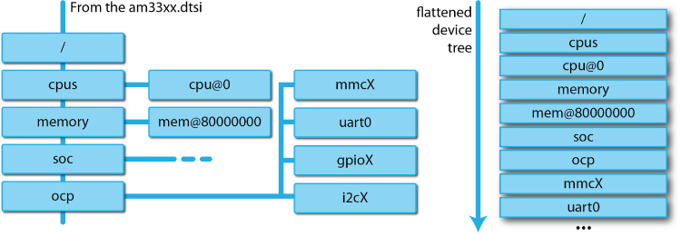
Figure 6-14: The flattened device tree on the AM335x
In the GitHub repository directory that follows, the device tree source files for the Beagle board Linux 4.17.0 kernel are made available so that you can review them:
debian@ebb:~/exploringbb/chp06/deviceTree/DTSource4.17.0$ lsam335x-boneblack-common.dtsi am335x-bonegreen.dtsam335x-boneblack.dts am335x-bonegreen-wireless.dtsam335x-boneblack-wireless.dts am335x-pocketbeagle-common.dtsiam335x-boneblue.dts am335x-pocketbeagle.dtsam335x-bone-common.dtsi am33xx.dtsiam335x-bone.dts am57xx-beagle-x15-common.dtsiam335x-bonegreen-common.dtsi am57xx-beagle-x15.dts
In particular, examine the beginning of the file, am335x-boneblack.dts (as shown in Listing 6-3), which describes the device tree for the BeagleBone Black. The file is short and largely just lists include files, segments of which are provided in Listing 6-4, Listing 6-5, and Listing 6-6.
Listing 6-3: chp06/deviceTree/DTSource4.17.0/am335x-boneblack.dts
/* Copyright (C) 2012 Texas Instruments Incorporated … *//dts-v1/;#include "am33xx.dtsi"#include "am335x-bone-common.dtsi"#include "am335x-boneblack-common.dtsi"/ {model = "TI AM335x BeagleBone Black";compatible = "ti,am335x-bone-black", "ti,am335x-bone", "ti,am33xx";};…
Listing 6-4: chp06/deviceTree/DTSource4.17.0/am33xx.dtsi
/* Device Tree Source for AM33XX SoC … */#include <dt-bindings/gpio/gpio.h>#include <dt-bindings/pinctrl/am33xx.h>#include <dt-bindings/clock/am3.h>/ {compatible = "ti,am33xx";interrupt-parent = <&intc>;chosen { };…ocp {compatible = "simple-bus";#address-cells = <1>;#size-cells = <1>;ranges;ti,hwmods = "l3_main";….gpio0: gpio@44e07000 {compatible = "ti,omap4-gpio";ti,hwmods = "gpio1";gpio-controller;interrupt-controller;reg = <0x44e07000 0x1000>;interrupts = <96>;};…uart0: serial@44e09000 {compatible = "ti,am3352-uart", "ti,omap3-uart";ti,hwmods = "uart1";clock-frequency = <48000000>;reg = <0x44e09000 0x2000>;interrupts = <72>;status = "disabled";dmas = <&edma 26 0>, <&edma 27 0>;dma-names = "tx", "rx";};…epwmss1: epwmss@48302000 {compatible = "ti,am33xx-pwmss";reg = <0x48302000 0x10>;ti,hwmods = "epwmss1";#address-cells = <1>;#size-cells = <1>;status = "disabled";ranges = <0x48302100 0x48302100 0x80 /* ECAP */0x48302180 0x48302180 0x80 /* EQEP */0x48302200 0x48302200 0x80>; /* EHRPWM */…};};};
Listing 6-5: DTSource4.17.0/am335x-bone-common.dtsi
/* Copyright (C) 2012 Texas Instruments Incorporated … *// {cpus {cpu@0 {cpu0-supply = <&dcdc2_reg>;};};memory@80000000 {device_type = "memory";reg = <0x80000000 0x10000000>; /* 256 MB */};chosen {stdout-path = &uart0;};leds {pinctrl-names = "default";pinctrl-0 = <&user_leds_s0>;compatible = "gpio-leds";led3 {label = "beaglebone:green:mmc0";gpios = <&gpio1 22 GPIO_ACTIVE_HIGH>;linux,default-trigger = "mmc0";default-state = "off";};…
Listing 6-6: /DTSource4.17.0/am335x-boneblack-common.dtsi
#include <<dt-bindings/display/tda998x.h>&mmc1 {vmmc-supply = <&vmmcsd_fixed>;};&mmc2 {vmmc-supply = <&vmmcsd_fixed>;pinctrl-names = "default";pinctrl-0 = <&emmc_pins>;bus-width = <8>;status = "okay";};&am33xx_pinmux {nxp_hdmi_bonelt_pins: nxp_hdmi_bonelt_pins {pinctrl-single,pins = <…};
These files describe the properties of the CPU, base memory, GPIOs, PWMs, UARTs, user LEDs, and more. There is a full description about what each field in the FDT means at elinux.org/Device_Tree_Usage.
Some of the values should look familiar; for example, the GPIO0 offset is listed as 44e10800, just as described in the “Memory-Based GPIO Switching (Advanced)” feature. You can see that the user led3 is attached to GPIO1_22, and by default it indicates activity on mmc0. Also, please note from Listing 6-4 that uart0 is present at address 44e09000, and one of the PWM outputs (epwmss1) is present at address 48302000, which is important later in this chapter.
These files are compiled into a binary form using a device tree compiler (DTC) and are placed on the Linux boot image at /boot/dtbs/, as shown by the following for the PocketBeagle:
debian@ebb:/boot/dtbs/4.14.35-ti-rt-r44$ ls -l am335x-pocketbeagle.dtb-rw-r--r-- 1 root root 124178 Apr 22 07:18 am335x-pocketbeagle.dtb
The DTC simply performs a file conversion from DTS (human-readable) to DTB (binary computer-readable) form. This is a straightforward and reversible process, quite different from compilation when using gcc/g++.
The DTB files are used as part of the boot process. To modify the hardware description that is configured on your board, you could modify these DTS files, compile them using the DTC, deploy them to the boot directory, and then reboot your board.
Modifying a Board Device Tree
It is possible to modify the board device tree by taking the device tree source, editing it, and then compiling it using the device tree compiler. It is, however, challenging to ensure that you have the precise versions of the device tree source files for your current build.
debian@ebb:~/exploringbb/chp06/deviceTree/DTSource4.17.0$ cp * /tmpdebian@ebb:~/exploringbb/chp06/deviceTree/DTSource4.17.0$ cd /tmpdebian@ebb:/tmp$ ls -l am335x-pocket*-rw-r--r-- 1 debian debian 64233 May 27 04:25 am335x-pocketbeagle-common.dtsi-rw-r--r-- 1 debian debian 27474 May 27 04:25 am335x-pocketbeagle.dtsdebian@ebb:/tmp$ dtc -versionVersion: DTC 1.4.4
Robert C. Nelson has provided a much more straightforward method for building the device tree binaries using a dtb-rebuilder script. You can download and use it as follows:
debian@ebb:~$ git clone git://github.com/RobertCNelson/dtb-rebuilder.gitdebian@ebb:~$ cd dtb-rebuilder/debian@ebb:~/dtb-rebuilder$ git branch* 4.4-tidebian@ebb:~/dtb-rebuilder$ uname -aLinux ebb 4.9.88-ti-rt-r111 #1 SMP PREEMPT RT …debian@ebb:~/dtb-rebuilder$ git checkout 4.9-tiBranch 4.9-ti set up to track remote branch 4.9-ti from origin.Switched to a new branch '4.9-ti'
where the branch is chosen according to the current board version.
You can then edit the device tree source files (.dts and .dtsi) to make any necessary modifications.
debian@ebb:~/dtb-rebuilder$ lsBindings COPYING dtc-overlay.sh include Makefile README scripts srcdebian@ebb:~/dtb-rebuilder$ cd src/arm/debian@ebb:~/dtb-rebuilder/src/arm$ ls am335x-pocketbeagle*am335x-pocketbeagle-common.dtsi am335x-pocketbeagle-simplegaming.dtsam335x-pocketbeagle.dts
In this case, a simple change is made to the PocketBeagle device tree to use a default trigger of “heartbeat” instead of “mmc1” for the USR3 on-board LED.
debian@ebb:~/dtb-rebuilder/src/arm$ nano am335x-pocketbeagle-common.dtsidebian@ebb:~/dtb-rebuilder/src/arm$ more am335x-pocketbeagle-common.dtsi…led@5 {label = "beaglebone:green:usr3";gpios = <&gpio1 24 GPIO_ACTIVE_HIGH>;linux,default-trigger = "heartbeat";default-state = "off";};…debian@ebb:~/dtb-rebuilder/src/arm$ cd ../../debian@ebb:~/dtb-rebuilder$ make alldebian@ebb:~/dtb-rebuilder/src/arm$ ls -l am335x-pocketbeagle.dtb-rw-r--r-- 1 debian debian 132761 May 27 04:52 am335x-pocketbeagle.dtb
You can back up the current device tree binary and replace it with this new binary as follows:
debian@ebb:/boot/dtbs/4.9.88-ti-rt-r111$ ls -l am335x-pocketbeagle.dtb-rw-r--r-- 1 root root 132757 Apr 22 11:44 am335x-pocketbeagle.dtb…$ sudo mv am335x-pocketbeagle.dtb am335x-pocketbeagle.dtb_backup…$ sudo cp ~/dtb-rebuilder/src/arm/am335x-pocketbeagle.dtb .…$ ls -l am335x-pocketbeagle.dtb-rw-r--r-- 1 root root 132761 May 27 04:57 am335x-pocketbeagle.dtb
On reboot, both the USR0 and USR3 LEDs now flash with a heartbeat pattern, and you can confirm their state in the usr3 sysfs directory.
debian@ebb:~$ cd /sys/class/leds/beaglebone:green:usr3debian@ebb:/sys/class/leds/beaglebone:green:usr3$ lsbrightness device invert max_brightness power subsystem trigger ueventdebian@ebb:/sys/class/leds/beaglebone:green:usr3$ cat triggernone … [heartbeat] backlight gpio default-on
Boot Configuration Files
Earlier Linux kernel versions on the BeagleBone used a kernel overlay “slots” framework (used throughout the first edition of this book) to allow for the dynamic reconfiguration of hardware, which was necessary when capes were plugged into a Beagle board. The capes identified themselves using identification and version codes that were stored in an on-board EEPROM. The kernel cape manager would use this information to search the /lib/firmware/ directory for the correct overlay. Kernel overlays are currently being phased out by the BeagleBoard.org development team and are being replaced by U-Boot overlays.
Currently, you have control over the configuration of hardware at boot time using the /boot/uEnv.txt configuration file, a segment of which is provided in Listing 6-7.
Listing 6-7: /boot/uEnv.txt (Segment)
#Docs: http://elinux.org/Beagleboard:U-boot_partitioning_layout_2.0uname_r=4.14.54-ti-rt-r63#uuid=#dtb=###U-Boot Overlays######Documentation: http://elinux.org/Beagleboard:BeagleBoneBlack_Debian#U-Boot_Overlays###Master Enableenable_uboot_overlays=1######Overide capes with eeprom#uboot_overlay_addr0=/lib/firmware/<file0>.dtbo…######Additional custom capes#uboot_overlay_addr4=/lib/firmware/<file4>.dtbo…######Custom Cape#dtb_overlay=/lib/firmware/<file8>.dtbo######Disable auto loading of virtual capes (emmc/video/wireless/adc)#disable_uboot_overlay_emmc=1#disable_uboot_overlay_video=1#disable_uboot_overlay_audio=1#disable_uboot_overlay_wireless=1#disable_uboot_overlay_adc=1######PRUSS OPTIONS###pru_rproc (4.4.x-ti kernel)#uboot_overlay_pru=/lib/firmware/AM335X-PRU-RPROC-4-4-TI-00A0.dtbo###pru_uio (4.4.x-ti, 4.14.x-ti & mainline/bone kernel)#uboot_overlay_pru=/lib/firmware/AM335X-PRU-UIO-00A0.dtbo######Cape Universal Enableenable_uboot_cape_universal=1######Debug: disable uboot autoload of Cape#disable_uboot_overlay_addr0=1…######U-Boot fdt tweaks… (60000 = 384KB)#uboot_fdt_buffer=0x60000###U-Boot Overlays###cmdline=coherent_pool=1M net.ifnames=0 quiet#In the event of edid real failures, uncomment this next line:#cmdline=coherent_pool=1M net.ifnames=0 quiet video=HDMI-A-1:1024x768@60e##enable Generic eMMC Flasher:##make sure, these tools are installed: dosfstools rsync#cmdline=init=/opt/scripts/tools/eMMC/init-eMMC-flasher-v3.sh
Currently, this configuration file allows you to
- Revert to the old kernel overlay “slots” model by commenting out the line
enable_uboot_overlays=1with a#. Do that at your own peril! - Disable on-board devices (e.g., the eMMC, HDMI, on-board Wi-Fi, and the ADCs) by uncommenting the associated line (e.g.,
disable_uboot_overlay_adc=1). - Provide support for a custom overlay by specifying it as follows:
dtb_overlay=/lib/firmware/<custom>.dtbo. The/lib/firmware/directory provides a repository of overlays. - Choose to enable overlays for the PRU-ICSS (
rpocoruio) as described in Chapter 15.
The Automatic Pin Configuration on Boot feature in Chapter 15 describes a method for initializing the mode of the header pins at boot time.
Analog Inputs and Outputs
In Chapter 4, the concept of analog-to-digital conversion was introduced, and an operational amplifier voltage-follower circuit was described that can be used to safely read analog inputs. This section describes how you can interface such a circuit to a Beagle board and use Linux sysfs to read values into your software applications.
Analog Inputs
The AM335x has a 12-bit successive approximation register (SAR) ADC that is capable of 200,000 samples per second. The input to the SAR is internally selected using an 8:1 analog switch, and the board makes seven of these switched inputs available on the P9/P1 header as ADC inputs. Among other things, the analog inputs can be configured to be used as a four-wire, five-wire, or eight-wire resistive touch screen controller (TSC), and this application is used in Chapter 13. In the current section, the ADC inputs are used as simple one-wire ADC inputs. By default, these inputs are enabled on the board.
Enabling the Analog Inputs
The analog inputs can be enabled with the use of a virtual cape that is loaded by default. To check that the virtual cape is not disabled (or to disable the cape), verify that the following entry is commented out as follows:
debian@ebb:/boot$ more uEnv.txt | grep adc###Disable auto loading of virtual capes (emmc/video/wireless/adc)#disable_uboot_overlay_adc=1
If the ADCs are enabled, then you can access them directly from sysfs using the /sys/bus/iio/devices/ directory, in which you will find file entries that allow you to read the raw ADC values directly.
debian@ebb:~$ cd /sys/bus/iiodebian@ebb:/sys/bus/iio$ lsdevices drivers drivers_autoprobe drivers_probe ueventdebian@ebb:/sys/bus/iio$ cd devices/debian@ebb:/sys/bus/iio/devices$ lsiio:device0debian@ebb:/sys/bus/iio/devices$ cd iio:device0debian@ebb:/sys/bus/iio/devices/iio:device0$ lsbuffer in_voltage2_raw in_voltage6_raw powerdev in_voltage3_raw in_voltage7_raw scan_elementsin_voltage0_raw in_voltage4_raw name subsystemin_voltage1_raw in_voltage5_raw of_node uevent
If you read the analog input (AIN0), using cat in_voltage0_raw, when nothing is connected, the result will be an integer value between 0 and 4,095. The Beagle boards have 12-bit ADCs (212 = 4,096), meaning a value between 0 and 212 − 1 (0 to 4,095) will be returned. You can test this by using the following:
debian@ebb:/sys/bus/iio/devices/iio:device0$ cat in_voltage0_raw3994debian@ebb:/sys/bus/iio/devices/iio:device0$ cat in_voltage0_raw3993
You can test the full range of an ADC input by connecting the input (P1.19/P9_39 AIN0) to the analog ground/negative pin (P1.17/P9_34 VREFN) and the voltage reference positive pin (P1.18/P9_32 VREFP) on the PocketBeagle/BeagleBone. Performing these connections results in the following outputs:
debian@ebb:/sys/bus/iio/devices/iio:device0$ cat in_voltage0_raw0debian@ebb:/sys/bus/iio/devices/iio:device0$ cat in_voltage0_raw4095
Next, a simple light-level meter application is built to demonstrate how you can attach sensor circuits to a Beagle board that can be used for sampling and data-logging applications.
Analog Input Application—A Simple Light Meter
To choose a suitable pairing resistor value R for a typical light-dependent resistor (LDR) voltage divider circuit, a good rule of thumb is to use the equation ![]() , where RMIN is the measured resistance of the LDR when it is covered (e.g., with your finger) and RMAX is the measured resistance of the LDR when a light source (e.g., phone torch app) is close to its surface. In this example, the resistance of the LDR was 6kΩ when covered and 100Ω when the light source was close. The preceding formula thus gives a value for R of 775 Ω, so the combination of a 470 Ω and a 330 Ω resistor in series provides a suitable value for the potential divider. You could wire the circuit as shown in Figure 6-15, but it is not a recommended configuration.
, where RMIN is the measured resistance of the LDR when it is covered (e.g., with your finger) and RMAX is the measured resistance of the LDR when a light source (e.g., phone torch app) is close to its surface. In this example, the resistance of the LDR was 6kΩ when covered and 100Ω when the light source was close. The preceding formula thus gives a value for R of 775 Ω, so the combination of a 470 Ω and a 330 Ω resistor in series provides a suitable value for the potential divider. You could wire the circuit as shown in Figure 6-15, but it is not a recommended configuration.
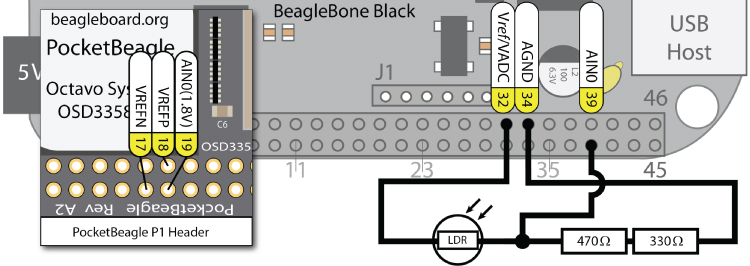
Figure 6-15: ADC LDR circuit (not recommended)
The problem with the circuit in Figure 6-15 is that it will draw a current from the Vref/VADC(P9_32) pin and act as a variable load. The resistance between Vref and AGND varies from 900Ω in the brightest case to 6.8kΩ in the darkest case. In the brightest case, because Vref = 1.8V, this means that the current being sourced from Vref, I = 1.8V/900Ω = 2mA. If you were to wire seven separate circuits like this one, you could end up sourcing up to 14mA from Vref, which could damage the board. The AM335x analog front end (AFE) switches between inputs, but the supply voltage will remain powered for all seven circuits. Even if the current is not large enough to damage the board, drawing current from Vref will affect the voltage level of the reference voltage itself, which defeats the purpose of having a reference voltage.
To avoid drawing any significant current from the 1.8V Vref pin, an op-amp voltage-follower circuit can be used. This op-amp configuration is discussed in Chapter 4. The implementation described in Figure 6-16 uses a LM358P (dual op-amp) IC, where VCC is connected to the SYS_5V rail (DC_3.3 V could also have been used) and the positive input (2IN+) to the second op-amp is the BeagleBone 1.8V analog reference voltage Vref/VADC(P9_32).
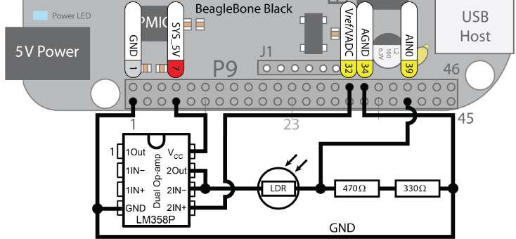
Figure 6-16: ADC LDR circuit using a voltage-follower circuit (recommended)
The raw voltage levels can be read from the ADC using sysfs. For the following sample values, the first reading was taken at regular room light levels, the second reading was taken with the LDR surface covered, and the third reading was taken with a light source very close to the sensor.
/sys/bus/iio/devices/iio:device0# cat in_voltage0_raw959/sys/bus/iio/devices/iio:device0# cat in_voltage0_raw304/sys/bus/iio/devices/iio:device0# cat in_voltage0_raw3651
The circuit provides a good range of decimal input values because of the resistor calculation at the start of this section. The current required for input offset and input biasing is typically 2nA and 20nA, respectively, for the LM358, meaning that it will not draw any significant current from the BeagleBone Vref pin (P9_32). The actual measured voltage and current values for this circuit are displayed in Figure 6-17, where the “light level” as read from in_voltage0_raw was the value 3,466. It should be clear from this figure that there is almost no current being sourced from or sinked to the analog Vref, AGND, or AIN0 pins, even though the current flowing through the LDR was about 2mA (as the light level in the room was bright and the LDR resistance was low).
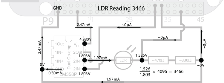
Figure 6-17: Measured voltages and current values with the op-amp in a voltage-follower configuration
Importantly, this configuration has no loading effect on the Vref output. This is in contrast to the configuration in Figure 6-15, where the LDR and resistors load the Vref output, skewing the reference voltage depending on the load, which varies according to the light level. Note that the 1.97mA current on the bottom GND rail was the current returning to the grounding point (it behaves exactly like the return connection from the resistor in Figure 4-2(a)).
Here is a simple C++ application that reads in the LDR value. It is structured so that it reads a single value from any of the AIN pins, by passing the pin number (0–6) to the readAnalog() function:
~/exploringbb/chp06/ADC# more readLDR.cpp#include<iostream>#include<fstream>#include<string>#include<sstream>using namespace std;#define LDR_PATH "/sys/bus/iio/devices/iio:device0/in_voltage"int readAnalog(int number){ // returns the input as an intstringstream ss;ss << LDR_PATH << number << "_raw";fstream fs;fs.open(ss.str().c_str(), fstream::in);fs >> number;fs.close();return number;}int main(int argc, char* argv[]){cout << "Starting the readLDR program" << endl;int value = readAnalog(0);cout << "The LDR value was " << value << " out of 4095." << endl;return 0;}~/exploringbb/chp06/ADC# g++ readLDR.cpp -o readLDR~/exploringbb/chp06/ADC# ./readLDRStarting the readLDR programThe LDR value was 463 out of 4095.
This code works perfectly for reading a sensor occasionally, but it is not good for reading a sensor many times per second.
Analog Outputs (PWM)
The next functionality to be examined is the use of the Beagle board's pulse-width modulation (PWM) outputs to provide low-frequency digital-to-analog conversion (DAC), or for the generation of control signals for motors and certain types of servos. There are eight PWM outputs on the AM335x, three eHRPWM modules (two outputs each), and two eCAP modules. These outputs are described in Figures 6-8 and 6-9, where you can see that the six eHRPWM outputs are each available on two separate pins (e.g., output 2B is available on P8_13 and P8_46). Please see Table 6-2 for the location of the PWMs on the BeagleBone Black (BBB) and PocketBeagle (PB) boards.2
Table 6-2: The PWMSS on the AM335x and the Connected Pins on the BeagleBone Black (BBB) and the PocketBeagle (PB) Boards
| HARDWARE NAME | HARDWARE ADDRESS | BBB CHIP3 | CHANNEL | BBB PINS | PB CHIP | BP PINS |
| EHRPWM0 | 0x48300200 |
pwmchip0
|
0A | P9_22/P9_31 |
pwmchip0
|
P1.08/P1.36 |
| 0x48300260 |
pwmchip0
|
0B | P9_21/P9_29 |
pwmchip0
|
P1.10/P1.33 | |
| EHRPWM1 | 0x48302200 |
pwmchip2
|
1A | P9_14/P8_36 |
pwmchip2
|
P2.01 |
| 0x48302260 |
pwmchip2
|
1B | P9_16/P8_34 |
pwmchip2
|
n/a | |
| EHRPWM2 | 0x48304200 |
pwmchip5
|
2A | P8_19/P8_45 |
pwmchip4
|
n/a |
| 0x48304260 |
pwmchip5
|
2B | P8_13/P8_46 |
pwmchip4
|
P2.03 | |
| ECAP0 | 0x48300100 |
pwmchipX
|
n/a | P9_42 | n/a | P2.29 |
| ECAP2 | 0x48304100 |
pwmchipX
|
n/a | P9_28 | n/a | P1.32/P2.30 |
See Chapter 15 in the AM335x TRM for full details on the Pulse-Width Modulation Subsystem (PWMSS). The Linux PWM system is described in detail at tiny.cc/beagle605.
To enable a PWM on an output pin, use the config-pin tool and choose the pwm setting. For example, to enable PWM on P1.08 on the PocketBeagle, use the following:
debian@ebb:~$ config-pin -a p1.08 pwmdebian@ebb:~$ config-pin -q p1.08P1_08 Mode: pwm
The PWM pins can then be controlled using the appropriate pwmchip device. Here's an example on the BeagleBone:
debian@ebb:/sys/class/pwm$ lspwmchip0 pwmchip2 pwmchip3 pwmchip5 pwmchip6
Or, here's an example on the PocketBeagle:
debian@ebb:/sys/class/pwm$ ls -l… pwmchip0 -> …/48300000.epwmss/48300200.pwm/pwm/pwmchip0… pwmchip2 -> …/48302000.epwmss/48302200.pwm/pwm/pwmchip2… pwmchip4 -> …/48304000.epwmss/48304200.pwm/pwm/pwmchip4
You can then control the PWM as follows:
debian@ebb:/sys/class/pwm$ cd pwmchip0debian@ebb:/sys/class/pwm/pwmchip0$ echo 0 > exportdebian@ebb:/sys/class/pwm/pwmchip0$ lsdevice export npwm power pwm-0:0 subsystem uevent unexportdebian@ebb:/sys/class/pwm/pwmchip0$ cd ..debian@ebb:/sys/class/pwm$ lspwm-0:0 pwmchip0 pwmchip2 pwmchip4debian@ebb:/sys/class/pwm$ cd pwm-0:0debian@ebb:/sys/class/pwm/pwm-0:0$ ls -l-rw-rw-r-- 1 root pwm 4096 Jul 17 05:27 capturelrwxrwxrwx 1 root pwm 0 Jul 17 05:27 device -> …-rw-rw-r-- 1 root pwm 4096 Jul 17 05:27 duty_cycle-rw-rw-r-- 1 root pwm 4096 Jul 17 05:27 enable-rw-rw-r-- 1 root pwm 4096 Jul 17 05:27 period-rw-rw-r-- 1 root pwm 4096 Jul 17 05:27 polaritydrwxrwxr-x 2 root pwm 0 Jul 17 05:27 powerlrwxrwxrwx 1 root pwm 0 Jul 17 05:27 subsystem -> …-rw-rw-r-- 1 root pwm 4096 Jul 17 05:27 uevent
To set up a PWM signal (EHRPWM0A), the period is supplied in nanoseconds. Therefore, to output a PWM signal that has a period of 4 μs and a 25 percent duty cycle, you set the time period as 1 μs and not the duty cycle percentage.
debian@ebb:/sys/class/pwm/pwm-0:0$ sudo sh -c "echo 4000 > period"debian@ebb:/sys/class/pwm/pwm-0:0$ sudo sh -c "echo 1000 > duty_cycle"debian@ebb:/sys/class/pwm/pwm-0:0$ cat polaritynormaldebian@ebb:/sys/class/pwm/pwm-0:0$ sudo sh -c "echo 1 > enable"
This results in the output in Figure 6-18(a). You can see from the measurements that the period is 4 μs and the frequency is 250 kHz (i.e., 1/4 μs).
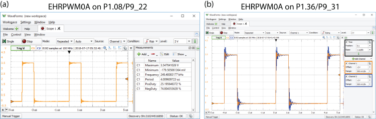
Figure 6-18: EHRPWM0A output for frequency of 250 kHz with a duty cycle of 25 percent
The same EHRPWM0A output is available on P1.36 on the PocketBeagle and can be enabled as follows:
debian@ebb:~$ config-pin -q p1.36P1_36 Mode: default Direction: in Value: 0debian@ebb:~$ config-pin -a p1.36 pwmdebian@ebb:~$ config-pin -q p1.36P1_36 Mode: pwm
This results in the output in Figure 6-18(b), which overlays both channels exactly.
Now, if you use both P1.08 and P1.10 on a PocketBeagle, which share the same PWM device but different channels (0A and 0B), the following occurs:
debian@ebb:~$ config-pin -a p1.10 pwmdebian@ebb:/sys/class/pwm/pwmchip0$ lsdevice npwm pwm-0:0 subsystem unexportexport power pwm-0:1 ueventdebian@ebb:/sys/class/pwm/pwm-0:1$ lscapture duty_cycle period power ueventdevice enable polarity subsystemdebian@ebb:/sys/class/pwm/pwm-0:1$ sudo sh -c "echo 4000 > period"debian@ebb:/sys/class/pwm/pwm-0:1$ sudo sh -c "echo 2000 > duty_cycle"debian@ebb:/sys/class/pwm/pwm-0:1$ cat polaritynormaldebian@ebb:/sys/class/pwm/pwm-0:1$ sudo sh -c "echo 1 > enable"
This results in the output in Figure 6-19(a) where both outputs have the same frequency but different duty cycles (25 percent and 50 percent in this case). Importantly, you cannot change the period when both channels are exported. In fact, to change the frequency of either channel, you must disable one channel beforehand. If you do not disable a channel or if you attempt to set a period duration (in nanoseconds) that is longer than the frequency duration (in nanoseconds), then you will see the following error:
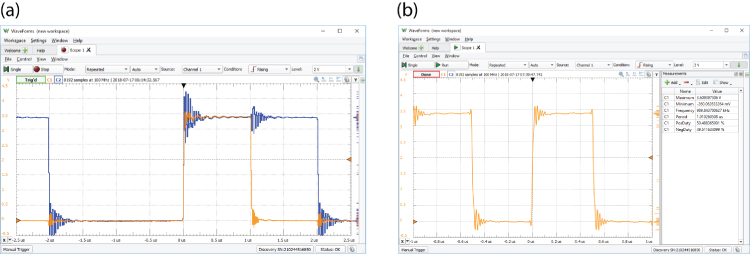
Figure 6-19: (a) Two PWM channels with a 25 percent and 50 percent duty cycle at 250kHz, and (b) PWM at 1MHz with a duty cycle of 50 percent
debian@ebb:/sys/class/pwm/pwm-0:0$ sudo sh -c "echo 8000 > period"sh: echo: I/O error
If you connect a DMM between the PWM pin and GND, the voltage measured with a 5,000 duty period should be 1.657V when the duty period is set as 5,000 and the period is set at 10,000 (that is, the output is 3.314V for half of each cycle and 0V for the other half, and the DMM averages this to 1.657V). Changing the duty cycle period results in the following DMM measurements by default: 0 → 3.314V, 2500 → 2.485 V, 7500 → 0.828 V, and 10,000 → 0.6 mV. This relationship can be inverted (i.e., 10,000 → 3.314 V) by changing the polarity echo inversed > polarity. Setting these values provides you with DAC capability that can be combined with an optocoupler to limit the current drawn from the GPIO pin.
Output Application—Controlling a Servo Motor
Servo motors consist of a DC motor that is attached to a potentiometer and a control circuit. The position of the motor shaft can be controlled by sending a PWM signal to the controller.
The Hitec HS-422 is a low-cost (less than $10), good quality, and widely available servo motor that can be supplied using a 5V supply. It is rated to rotate ±45° from the center. It can rotate in the range ±90°, but the potentiometer does not behave in a linear manner outside of the ±45° range. According to its datasheet, the HS-422 expects a pulse every 20ms that has a duration from 1100μs (to set the position to −45° from the center position) to 1900μs (to set the position to +45° from the center position). The center position can be set by passing a pulse of 1500μs in duration.
Figure 6-20 illustrates the connections and timings for the servo motor that enables it to rotate from −90° using a pulse of 570μs to +90° using a pulse of 2350μs. These values and the center point of 1460μs were manually calibrated and will vary for each individual servo motor.
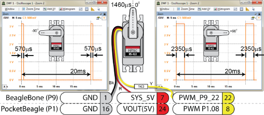
Figure 6-20: Controlling a servo motor using PWM, positioning from −90° to +90° using different pulse widths
The servo motor has three leads: black, red, and yellow. The black lead is connected to GND (P9_01/P1.16), the red lead is connected to a 5V supply (P9_07/P1.24), and the yellow lead is connected via a 1kΩ resistor to the PWM output (ehrpwm0A) on P9_22/P1.08. The 1kΩ resistor limits the current sourced from P9_22/P1.08 to about 0.01mA. To manually control a servo motor using sysfs, perform the following steps:
debian@ebb:/sys/class/pwm/pwmchip0$ echo 0 > exportdebian@ebb:/sys/class/pwm/pwmchip0$ cd ..debian@ebb:/sys/class/pwm$ lspwm-0:0 pwmchip0 pwmchip2 pwmchip4debian@ebb:/sys/class/pwm$ cd pwm-0:0
The polarity value should be set to normal for servo motors so that the duty value represents the duration of a high pulse. If the polarity value is inversed, then the signal is inverted, and the duty_cycle value would effectively specify the duration of a low pulse, with the signal being high for the remainder of the period. The period is set to 20ms, and the output is enabled.
…/sys/class/pwm/pwm-0:0$ sudo sh -c "echo normal > polarity"…/sys/class/pwm/pwm-0:0$ sudo sh -c "echo 20000000 > period"…/sys/class/pwm/pwm-0:0$ sudo sh -c "echo 1 > enable"
The arm can be rotated to −90°, followed by 0°, and then +90°, with the last step turning off the output, removing the holding torque, and reducing the power consumption of the motor:
…/sys/class/pwm/pwm-0:0$ sudo sh -c "echo 570000 > duty_cycle"…/sys/class/pwm/pwm-0:0$ sudo sh -c "echo 1460000 > duty_cycle"…/sys/class/pwm/pwm-0:0$ sudo sh -c "echo 2350000 > duty_cycle"…/sys/class/pwm/pwm-0:0$ sudo sh -c "echo 0 > enable"
BoneScript
As initially described in Chapter 2, BoneScript is a JavaScript library for physical computing on the Beagle boards using the Node.js interpreter. The JavaScript language uses asynchronous callback functions, and you can build applications using the Cloud9 IDE or by executing code at the Linux terminal prompt. In this section, the BoneScript library is used for interfacing the Beagle boards to digital and analog input/output circuits, providing you with a quick way to build prototype circuits with the Beagle boards.
Digital Read and Write
Listing 6-8 gives a simple digital read/write example that replicates some of the functionality described in the C/C++ examples when the board is wired, as in Figure 6-3 and Figure 6-6. This program flashes an LED (attached to GPIO 60) five times, while simultaneously reading the button input (attached to GPIO 46) one time.
Listing 6-8: /chp06/bone/simple.js
var b = require('bonescript');var led = "P2_08"; // GPIO1_28 (GPIO 60)var button = "P2_22"; // GPIO1_14 (GPIO 46)var isOn = false; // isOn is a Boolean flagconsole.log('Setting up the inputs and outputs');b.getPlatform(displayPlatform);b.pinMode(button, b.INPUT, 7, 'pullup', 'fast');b.pinMode(led, b.OUTPUT);console.log('Flashing the LED on GPIO 60');timer = setInterval(toggleLED, 500); // each 0.5s call toggleLED()setTimeout(stopTimer, 5000); // stop after 5 secondsconsole.log('Reading the button on GPIO 46');b.digitalRead(button, display);console.log('End of the application');function displayPlatform(platform){console.log('Platform name is ' + platform.name);};function toggleLED(){isOn = !isOn; // invert the isOn state on each callif (isOn) b.digitalWrite(led, 1); // light the LEDelse b.digitalWrite(led, 0); // turn off the LED};function stopTimer(){clearInterval(timer);};function display(x) {console.log('Button value = ' + x.value);};
When you execute the code, you will notice a short delay before anything happens. This is caused by the time required to load and initialize Node.js and the BoneScript library. The code example gives the outputs as follows, executed both when the button is pressed and when the button is released:
debian@ebb:~/exploringbb/chp06/bone$ node simple.jsSetting up the inputs and outputsPlatform name is TI AM335x PocketBeagleFlashing the LED on GPIO 60Reading the button on GPIO 46End of the applicationButton value = 1debian@ebb:~/exploringbb/chp06/bone$ node simple.jsSetting up the inputs and outputsPlatform name is TI AM335x PocketBeagleFlashing the LED on GPIO 60Reading the button on GPIO 46End of the applicationButton value = 0
Analog Read
Listing 6-9 provides an example of reading an ADC input using Node.js and the BoneScript library. This example tests P2.35 on the PocketBeagle, which is a 3.3V input, but any ADC input can be used in its place.
Listing 6-9: /chp06/bone/analogRead.js
var b = require('bonescript');var adc = "P2.35"; // AIN0 P1.19 AIN1 P1.21 AIN2 P1.23// AIN3 P1.25 AIN4 P1.27 AIN5 P2.35 (3.3)// AIN6 P1.02 (3.3V) AIN7 P2.36var sampleTime = 1000;var endTime = 10000;console.log('Reading AIN on '+adc+' every '+sampleTime+'ms');timer = setInterval(readAIN, sampleTime);setTimeout(stopTimer, endTime);function readAIN() {value = b.analogRead(adc);console.log('ADC Value = ' + value);};function stopTimer(){clearInterval(timer);};
This code example reads one of the ADC inputs once per second for 10 seconds and displays the output on the console. When AIN5 is chosen and the input is varied between 3.3 V and GND, the resulting output is as follows:
debian@ebb:~/exploringbb/chp06/bone$ node analogRead.jsReading AIN on P2.35 every 1000msADC Value = 0.9545787545787546ADC Value = 0.9545787545787546ADC Value = 0ADC Value = 0ADC Value = 0ADC Value = 0ADC Value = 0.9543345543345544ADC Value = 0.9543345543345544ADC Value = 0.9545787545787546
The analogRead() function returns the normalized voltage (e.g., where 0.0 = 0 V and 1 .0 = 1.8V for a 1.8V input) that represents the voltage on the ADC input.
Analog Write (PWM)
BoneScript provides support for pulse width modulation (PWM) outputs through its analogWrite() function. In Listing 6-10 this function is supplied with the pin number as a string (“P2.01”), the duty cycle value as a normalized float (e.g., 0.75), the modulation frequency in Hz, and a callback function (display()) to be called on its completion. It's important to ensure that you have not exported any PWM outputs in sysfs related to the PWMs that are used in your program code, as they can conflict.
Listing 6-10: /chp06/bone/pwm.js
var b = require('bonescript');var pin = "P2_01";var dutyCycle = 0.75;var frequency = 10000;b.pinMode(pin, b.OUTPUT);b.getPinMode(pin, printPinMux);b.analogWrite(pin, dutyCycle, frequency, display);function printPinMux(val){console.log('mux = '+val.mux);console.log('name = '+val.name);}function display(val){console.log(val);}
To execute this example, you must do so with root privileges under the current Linux distributions, as the library utilizes the same type of sysfs calls that are described earlier in the chapter.
debian@ebb:~/exploringbb/chp06/bone$ sudo nodejs pwm.js{}mux = 6name = EHRPWM1A
The output from this code example is visible in Figure 6-21(a), which confirms an output frequency of 10kHz and a duty cycle of 75 percent.
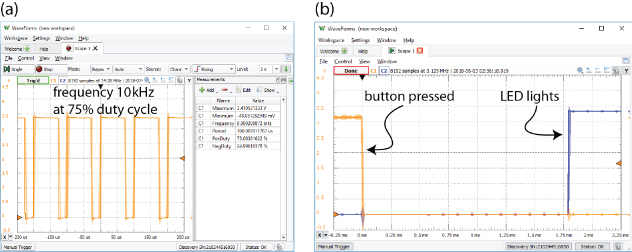
Figure 6-21: BoneScript output for (a) the PWM example, and (b) the button/LED response example
GPIO Performance
The final BoneScript code example in this section, Listing 6-11, is used to evaluate how quickly BoneScript can respond to hardware events. In this example, a button on GPIO 46 is used to trigger a change in the output value of an LED that is attached to GPIO 60. An oscilloscope can then be used to determine the precise time between the button press taking place and the subsequent state change of the LED.
Listing 6-11: /chp06/bone/gpioTest.js
var b = require('bonescript');var led = "P2_08"; // GPIO1_28 (GPIO 60)var button = "P2_22"; // GPIO1_14 (GPIO 46)var isOn = false; // isOn is a Boolean flagconsole.log('Testing the inputs output response');b.getPlatform(displayPlatform);b.pinMode(button, b.INPUT, 7, 'pullup', 'fast');b.pinMode(led, b.OUTPUT);console.log('Attaching interrupt to GPIO 46');b.attachInterrupt(button, true, b.CHANGE, buttonPressed);console.log('End of the application');function displayPlatform(platform){console.log('Platform name is ' + platform.name);};function buttonPressed(){isOn = !isOn; // invert the isOn state on each callif (isOn) b.digitalWrite(led, 1); // light the LEDelse b.digitalWrite(led, 0); // turn off the LED};
You can execute this code as follows to perform the test:
debian@ebb:~/exploringbb/chp06/bone$ node gpioTest.jsTesting the inputs output responsePlatform name is TI AM335x PocketBeagleAttaching interrupt to GPIO 46End of the application
The program stays running until Ctrl+C is pressed in the Linux terminal window. The LED will toggle when the button is pressed and toggle again when the button is released. The scope output in Figure 6-21(b) indicates that the response time is approximately 1.75ms between the time when the button is pressed and the LED lights.
If this level of performance is not sufficient for your particular application, then you might consider implementing the Enhanced GPIO class toward the end of this chapter, which has a response time of 0.3ms for the same circuit configuration.
Advanced GPIO Topics
One serious problem with the GPIO digital input application described earlier is that it requires the sysfs file to be repeatedly polled to determine whether a change in its state has occurred. This is processor intensive, or prone to long latency if the frequency of the checks is reduced. This section examines how this problem can be addressed using a significant enhancement of the GPIO C++ class.
More C++ Programming
To understand the first technique, it is necessary to examine some additional programming concepts in C/C++ that are to be used and that can be applied generally to enhance your Beagle board applications. Callback function, POSIX threads, and use of Linux system polling can be used to create a highly efficient GPIO poll that has negligible CPU overhead and fast response times (i.e., less than 0.5ms). The GPIO class that is written for this chapter is enhanced to support this functionality, so an overview of these programming techniques is all that you require.
Callback Functions
Chapter 2 describes the use of callback functions as they are used in Node.js with asynchronous function calls. Essentially, a callback function (or listener function) is a function that is executed when some type of event occurs. This is vital for asynchronous function calls like those in JavaScript, but it is also useful in C++ applications. For example, in the enhanced GPIO class, this structure is used so that a function can be executed when a physical button is pressed.
Callback functions are typically implemented in C++ using function pointers. Function pointers are pointers that store the address of a function. It is possible to pass these pointers to other functions, which can dereference the function pointer and call the function that is passed. This is demonstrated with the code example in Listing 6-12.
Listing 6-12: /chp06/callback/callback.cpp
typedef int (*CallbackType)(int);// some function that receives a callback functionint doSomething(CallbackType callback){return callback(10); //execute callback function, pass 10}// the callback function that receives an int valueint callbackFunction(int var){cout << "I am the Callback Function! var=" << var << endl;return 2*var;}int main() {cout << "Hello Beagle board" << endl;// pass the address of the callbackFunction() to doSomething()int y = doSomething(&callbackFunction);cout << "Value of y is: " << y << endl;}
Creating a type using typedef simply makes it easier to change the type at a later stage and cleans up the syntax somewhat. The address of the callbackFunction() method is passed as a pointer to the doSomething() function. When executed, the output of this code is as follows:
Hello Beagle boardI am the Callback Function! var=10Value of y is: 20
This programming structure is quite common in (and underneath) user-interface programming, where functions can be called when a user interacts with display user-interface components such as buttons and menus. It makes sense to apply the same structure to physical push buttons and switches.
POSIX Threads
POSIX threads (Pthreads) is a set of C functions, types, and constants that provides everything you need to implement threading within your C/C++ applications on a Beagle board. Adding threading to your code allows parts of your code to execute apparently concurrently (the AM335x has a single-core processor), with each thread receiving a “slice” of processing time.
To use Pthreads in your application, you need to include the pthread.h header file and use the -pthread flag when compiling and linking the code using gcc/g++4. All the Pthread functions are prefixed with pthread_. Listing 6-13 is an example of using Pthreads on the board to create two parallel counters (the comments describe the structure of the code).
Listing 6-13: /chp06/pthreads/pthreads.cpp
#include <iostream>#include <pthread.h>#include <unistd.h>using namespace std;// Thread function that will execute when the thread is created// it passes and receives data by void pointers (See Chapter 5)void *threadFunction(void *value){int *x = (int *)value; // cast the data passed to an int pointerwhile(*x<5){ // while the value of x is less than 5usleep(1000); // sleep for 1ms - encourage main thread(*x)++; // increment the value of x by 1}return x; // return the pointer x (as a void*)}int main() { // the main threadint x=0, y=0;pthread_t thread; // this is our handle to the pthread// create thread, pass reference, addr of the function and dataif(pthread_create(&thread, NULL, &threadFunction, &x)){cout << "Failed to create the thread" << endl;return 1;}// at this point the thread was created successfullywhile(y<5){ // loop and increment y, displaying valuescout << "The value of x=" << x << " and y=" << y++ << endl;usleep(1000); // encourage the pthread to run}void* result; // OPTIONAL: receive data back from pthreadpthread_join(thread, &result); // allow the pthread to completeint *z = (int *) result; // cast from void* to int* to get zcout << "Final: x=" << x << ", y=" << y << " and z=" << *z << endl;return 0;}
Building and executing as follows will result in the following output:
~/exploringbb/chp06/pthreads$ g++ -pthread pthreads.cpp -o pthreads~/exploringbb/chp06/pthreads$ ./pthreadsThe value of x=0 and y=0The value of x=0 and y=1The value of x=1 and y=2The value of x=2 and y=3The value of x=3 and y=4Final: x=5, y=5 and z=5
Run it again, and you may get a different output!
The value of x=0 and y=0The value of x=1 and y=1The value of x=1 and y=2The value of x=2 and y=3The value of x=3 and y=4Final: x=5, y=5 and z=5
The code may result in a slightly different result each time. The usleep() calls have been introduced to encourage the thread manager to switch to the main thread at that point. While the order of the output may change, the final results will always be consistent because of the pthread_join() function call, which blocks execution at this point until the thread has run to completion.
Linux poll (sys/poll.h)
At the beginning of this chapter, code is presented that can be used to detect the state of a button by checking the state of the value file. This is a very processor-intensive operation and not really practical. If you listed the contents of the /sys/class/gpio/ directory, you may have also noticed a file entry called edge that up to now has had no relevance.
debian@ebb:/sys/class/gpio$ cd gpio115debian@ebb:/sys/class/gpio/gpio115$ lsactive_low device direction edge label powersubsystem uevent value
You can use a system function called poll() from the sys/poll.h header file, which has the following syntax:
int poll(struct pollfd *ufds, unsigned int nfds, int timeout); where the first argument specifies a pointer to an array of pollfd structures, each of which identifies a file entry to be monitored and the type of event to be monitored (e.g., EPOLLIN to read operations, EPOLLET edge triggered, and EPOLLPRI for urgent data). The next argument, nfds, identifies how many elements are in the first argument array. The final argument identifies a timeout in milliseconds. If this value is -1, then the kernel will wait forever for the activity identified in the array. This code has been added to the following enhanced GPIO class in the waitForEdge() methods.
Enhanced GPIO Class
The programming concepts just discussed are complex and may be difficult to understand if it is your first time seeing them; however, these techniques have been used to enhance the GPIO class so that it is faster and more efficient than before. The code in Listing 6-14 integrates the earlier GPIO functionality and the programming concepts that have been just introduced. The public interface methods are also provided.
Listing 6-14: /chp06/GPIO/GPIO.h
#define GPIO_PATH "/sys/class/gpio/"namespace exploringBB {typedef int (*CallbackType)(int);enum GPIO_DIRECTION{ INPUT, OUTPUT };enum GPIO_VALUE{ LOW=0, HIGH=1 };enum GPIO_EDGE{ NONE, RISING, FALLING, BOTH };class GPIO {private:int number, debounceTime;string name, path;public:GPIO(int number); //constructor will export the pinvirtual int getNumber() { return number; }// General Input and Output Settingsvirtual int setDirection(GPIO_DIRECTION);virtual GPIO_DIRECTION getDirection();virtual int setValue(GPIO_VALUE);virtual int toggleOutput();virtual GPIO_VALUE getValue();virtual int setActiveLow(bool isLow=true); //low=1, high=0virtual int setActiveHigh(); //default//software debounce input (ms) - default 0virtual void setDebounceTime(int time) { this->debounceTime = time; }// Advanced OUTPUT: Faster write by keeping the stream alive (~20X)virtual int streamOpen();virtual int streamWrite(GPIO_VALUE);virtual int streamClose();virtual int toggleOutput(int time); //threaded invert output every X ms.virtual int toggleOutput(int numberOfTimes, int time);virtual void changeToggleTime(int time) { this->togglePeriod = time; }virtual void toggleCancel() { this->threadRunning = false; }// Advanced INPUT: Detect input edges; threaded and non-threadedvirtual int setEdgeType(GPIO_EDGE);virtual GPIO_EDGE getEdgeType();virtual int waitForEdge(); // waits until button is pressedvirtual int waitForEdge(CallbackType callback); // threaded with callbackvirtual void waitForEdgeCancel() { this->threadRunning = false; }virtual ~GPIO(); //destructor will unexport the pin…} /* namespace exploringBB */
The tests to evaluate the performance of the class are provided as examples of how to use this class. The test circuit is the combination of the button circuit in Figure 6-6 and the LED circuit in Figure 6-3. Therefore, the button is attached to P8_16/P2.22 (GPIO 46), and the LED is attached to P9_12/P2.08 (GPIO 60). In these tests, the LED will light when the button is pressed.
Listing 6-15 tests the performance of a synchronous poll that forces the program to wait for the button to be pressed before proceeding.
Listing 6-15: /chp06/GPIO/tests/test_syspoll.cpp
#include<iostream>#include<unistd.h>#include"GPIO.h"using namespace exploringBB;using namespace std;int main(){GPIO outGPIO(60), inGPIO(46);inGPIO.setDirection(INPUT); //button is an inputoutGPIO.setDirection(OUTPUT); //LED is an outputinGPIO.setEdgeType(FALLING); //wait for falling edgeoutGPIO.streamOpen(); //fast write, ready fileoutGPIO.streamWrite(LOW); //turn the LED offcout << "Press the button:" << endl;inGPIO.waitForEdge(); //will wait foreveroutGPIO.streamWrite(HIGH); //button pressed, light LEDoutGPIO.streamClose(); //close the output streamreturn 0;}
The response time of this code is captured in Figure 6-22(a). This code runs with a ~0% CPU load, as the polling is handled efficiently by the Linux kernel. Using an oscilloscope, the electrical response time is measured between the first rising edge of the button press and the LED turning on. This program responds in 0.3 ms, which is well within physical debounce filter times. Using the debounce filter of the class will not affect this performance, only the delay between repeated button presses. The downside of this code is that the program cannot perform other operations while awaiting the button press.
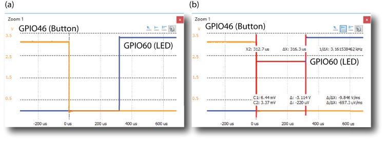
Figure 6-22: Time delay in lighting an LED in response to a button press at ~0 percent CPU usage (a) using sys/poll.h (b) integrating callback functions and Pthreads
The second example, in Listing 6-16, tests the performance of an asynchronous call to the waitForEdge()method, which accepts a function pointer and uses Pthreads to free up the program to perform other operations. In this example, the main thread sleeps, but it could be performing other tasks.
Listing 6-16: /chp06/GPIO/tests/test_callback.cpp
#include<iostream>#include<unistd.h> //for usleep#include"GPIO.h"using namespace exploringBB;using namespace std;GPIO *outGPIO, *inGPIO; //global pointersint activateLED(int var){outGPIO->streamWrite(HIGH); //turn on the LEDcout << "Button Pressed" << endl;return 0;}int main(){inGPIO = new GPIO(46); //buttonoutGPIO = new GPIO(60); //LEDinGPIO->setDirection(INPUT); //button is an inputoutGPIO->setDirection(OUTPUT); //LED is an outputoutGPIO->streamOpen(); //fast write to LEDoutGPIO->streamWrite(LOW); //turn the LED offinGPIO->setEdgeType(RISING); //wait for rising edgecout << "You have 10 seconds to press the button:" << endl;inGPIO->waitForEdge(&activateLED); //pass the functioncout << "Listening, but also doing something else…" << endl;usleep(10000000); //allow 10 secondsoutGPIO->streamWrite(LOW); //turn off the LED after 10 secondsoutGPIO->streamClose(); //shutdownreturn 0;}
The significant change in this code is that when the setEdgeType() method is called, a new thread is created within the method, and it immediately returns control so that the main thread can continue to perform operations. The main thread simply sleeps for 10 seconds in this case before turning off the LED. If the button is pressed, the activateLED() function will be called. Whether the button is pressed or not, the LED will be turned off, and the program will exit after the sleep has finished.
The response time of this code is captured in Figure 6-22(b), and it is only marginally slower than the previous code (by ~20μs), which is the cost of the callback function and the Pthreads code. Again, this code has no significant load on the CPU. The full implementation code is available in the GPIO.cpp file, and it can be edited to suit your needs. A more advanced version would use functors (function objects) and the C++ Standard Template Library (STL) to remove the requirement for global variables in the callback code.
Using GPIOs without Using sudo
Throughout this chapter, programs and scripts that interface to the input/outputs (e.g., PWM outputs) are sometimes executed using sudo. This can be frustrating, but the alternative of running applications as the superuser is dangerous, in that a coding mistake could damage the file system.
The latest Debian images for the Beagle boards do not require root access to control the GPIOs, allowing them to be owned by a particular user or group, while still protecting the root file system. This is achieved by the use of an advanced feature of Linux called udev rules that enables you to customize the behavior of the udevd service, which runs on the Debian Linux distribution. This service gives you some userspace control over devices on the boards, such as renaming devices, changing permissions, and executing a script when a device is attached. The first step is to find out information about the /sys/class/gpio/ directory.
debian@ebb:~$ udevadm info --path=/sys/class/gpio --attribute-walkUdevadm info starts with the device specified by the devpath and thenwalks up the chain of parent devices. It prints for every devicefound, all possible attributes in the udev rules key format.A rule to match, can be composed by the attributes of the deviceand the attributes from one single parent device.looking at device '/class/gpio':KERNEL=="gpio"SUBSYSTEM=="subsystem"DRIVER=="" …
The rules are contained in the /etc/udev/rules.d/ directory. A new rule can be added as a file using these values, where the file begins with a priority number, where a lower number indicates a higher priority. The current set of rules on the Debian distribution is as follows:
debian@ebb:/etc/udev/rules.d$ ls50-hidraw.rules 81-pwm-noroot.rules beagle-tester.rules50-spi.rules 82-gpio-config-pin.rules tisdk.rules60-omap-tty.rules 83-eqep-noroot.rules uio.rules70-persistent-net.rules 84-gpio-noroot.rules80-gpio-noroot.rules 85-gpio-noroot.rules
The GPIO rule has a mid-to-low-level priority (80) so that it does not interfere with higher-priority device rules. The rule dynamically changes GPIO permissions so that they can be read or written to by users that are in the Linux gpio group.
debian@ebb:/etc/udev/rules.d$ more 80-gpio-noroot.rules# /etc/udev/rules.d/80-gpio-noroot.rules# Corrects sys GPIO permissions on the BB so non-root users in the# gpio group can manipulate bits# Change group to gpioSUBSYSTEM=="gpio", PROGRAM="/bin/sh -c '/bin/chown -R root:gpio →/sys/devices/platform/ocp/*.gpio'"# Change permissions to ensure user and group have read/write permissionsSUBSYSTEM=="gpio", PROGRAM="/bin/sh -c '/bin/chmod -R ug+rw →/sys/devices/platform/ocp/*.gpio'"
Essentially, the rule executes a single line script to change the group of a GPIO device to be gpio when it is added. You can edit this rule if for example you want to apply it only for a particular user and test that it works as follows:
debian@ebb:/etc/udev/rules.d$ udevadm test --action=add /class/gpiocalling: testversion 232…Reading rules file: /etc/udev/rules.d/80-gpio-noroot.rules…ACTION=addDEVPATH=/class/gpioSUBSYSTEM=subsystemUSEC_INITIALIZED=245064723516net.ifnames=0Unload module indexUnloaded link configuration context.
For a comprehensive guide on writing udev rules, see tiny.cc/beagle607.
Root Permissions with setuid
An alternative to writing udev rules for your application is to use the Linux setuid bit. As described in Chapter 3, this bit allows a program to be executed as if by another logged-in user, but with the permissions of the file's owner or group. To test this functionality, a short program is written in Listing 6-17. This program uses the Linux geteuid() function to get the effective user ID of the user executing the binary code. If this function returns the value 0, then the user has full root access rights to the system and can access any input or outputs regardless of their permissions.
Listing 6-17: /chp06/root/root_test.c
#include <stdio.h>#include <stdlib.h>#include <fcntl.h>#include <errno.h>#include <stdint.h>#include <unistd.h>int main(){printf("Start of GPIO test program. ");if(geteuid()!=0) { // Get effective UIDprintf("You must run this program as root. Exiting. ");return -EPERM;}printf("Doing something here with root privileges! ");return 0;}
This program can be built and executed as follows, whereupon the program will fail to get to the section of code that is restricted to the root user.
debian@ebb:~/exploringbb/chp06/root$ gcc root_test.c -o root_testdebian@ebb:~/exploringbb/chp06/root$ ./root_testStart of GPIO test program.You must run this program as root. Exiting.
You could try to change the owner of the program to root (allowing execute permissions for group and others) and execute it as the user debian, but this will fail. Here's an example:
debian@ebb:~/exploringbb/chp06/root$ sudo chown root root_test[sudo] password for debian:debian@ebb:~/exploringbb/chp06/root$ ls -l root_test-rwxr-xr-x 1 root debian 8384 Jul 18 02:06 root_testdebian@ebb:~/exploringbb/chp06/root$ ./root_testStart of GPIO test program.You must run this program as root. Exiting.
Changing the owner to root is insufficient because the program is still executed by the debian user. However, when the setuid bit is set and the file is owned by root, then the program is executed as if by root, regardless of the actual user account that executes it.
debian@ebb:~/exploringbb/chp06/root$ sudo chmod u+s root_testdebian@ebb:~/exploringbb/chp06/root$ ls -l root_test-rwsr-xr-x 1 root debian 8384 Jul 18 02:12 root_testdebian@ebb:~/exploringbb/chp06/root$ ./root_testStart of GPIO test program.Doing something here with root privileges!
If you rebuild the executable again, then the setuid bit is unset (even if you use sudo on the call to g++). This is for security reasons because otherwise a user could insert malicious source code into the binary executable.
debian@ebb:~/exploringbb/chp06/root$ gcc root_test.c -o root_testdebian@ebb:~/exploringbb/chp06/root$ ls -l root_test-rwxr-xr-x 1 debian debian 8384 Jul 18 02:14 root_test
Summary
After completing this chapter, you should be able to do the following:
- Use a Beagle board GPIO to output a binary signal to a digital circuit or read in a binary input from a digital circuit.
- Write shell scripts and C++ code to control a Beagle board GPIO.
- Describe the use of internal pull-up and pull-down resistors.
- Describe the device tree model that is used to configure certain hardware on the Beagle boards and make minor modifications to the model.
- Use a PWM pin to output an analog voltage or as a control signal for motors and certain types of servos.
- Use an analog input to safely read in a value from an analog circuit, using an op-amp to protect the board from damage and/or invalid measurement.
- Write C++ code, which utilizes advanced functionality, to efficiently read in a digital input using a custom
GPIOclass. - Use an advanced Linux configuration that allows for user-level control of the sysfs entries.
Further Reading
There are many links to websites and documents provided throughout this chapter. The following additional links provide further information on the topics covered:
www.exploringbeaglebone.com/chapter6/:All links and videos in the chapter are provided at this site.www.exploringbeaglebone.com/API/:Provides the documentation for the classes described in this chapter.