
C H A P T E R 9
![]()
Digital Art: Drawing in GIMP
Digital art can be created in many different ways, with many different tools. You can create digital art without freehand painting and a graphics tablet. This chapter will show you how you can create digital art with GIMP’s tools.
In This Chapter
- How to draw in GIMP
- Draw with selections
- Drawing freely
- Paint without a tablet
How to Draw in GIMP
In principle, all painting tools can be used for drawing, too. How can you create geometric forms with only a mouse and no assistive tools like a drawing pad? It can be achieved by doing any of the following:
- Drawing freehand aided by GIMP (for example, straight lines)
- Creating a selection that reflects any geometric form (for example, circles, ellipses, or squares) and filling or stroking the outline with a paint tool
- Emulating the painting with the dedicated paths tool
You can also refer to Chapter 8, where we introduced every aspect of choosing foreground colors and paint tools, as well as navigating your workspace.
Tools for Drawing
All paint tools under Tools ![]() Paint Tools can be used for drawing. Most of the paint tools are more suitable for painting with a graphics tablet, but the following can be used for drawing with GIMP utilizing a mouse:
Paint Tools can be used for drawing. Most of the paint tools are more suitable for painting with a graphics tablet, but the following can be used for drawing with GIMP utilizing a mouse:
- Pencil: Draws lines with hard edges
- Paintbrush: Draws lines with soft edges
- Eraser: Removes strokes or parts of the drawing
- Airbrush: Draws fuzzy lines
- Ink: Writes calligraphy style lines
- Bucket Fill: Fills areas with a color
Size and Shapes
Every paint tool provides tool options, which allow tuning every bit of the paint tool (see Figure 9-1). The size you are drawing with and the shape of the brush will be most important to you.
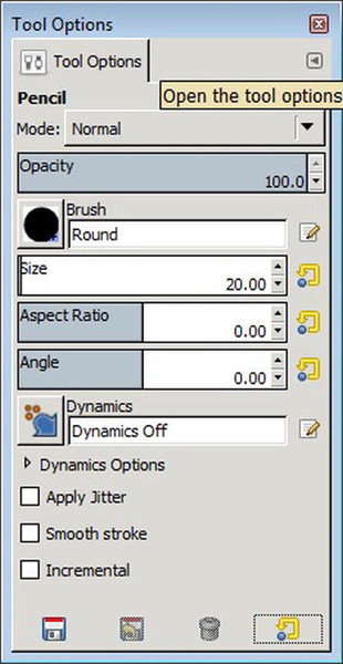
Figure 9-1. The tool options give you quick access to change the shape and size of your current brush.
Changing the Size and Shape of a Paint Tool
The mouse cursor in GIMP always shows a visual representation of the selected paint tool when you move the cursor over the canvas. The selected brush size and shape is also shown (see Figure 9-2). This makes it easy to change the size in the tool options quickly.
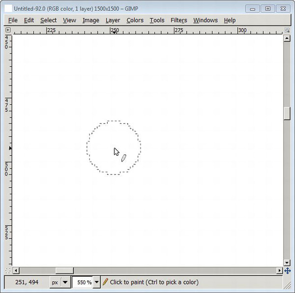
Figure 9-2. The shape and size of the current brush is displayed when you hover your mouse over the image.
- Create a new image.
- Select a paint tool under Tools
Paint Tools. You can select the Pencil, if you are unsure what to use.
- Move the mouse cursor over the white area of the canvas. You will notice the helping cursor showing the size of the brush.
- Open the paint tool options by double-clicking on the tool icon in the toolbox.
- Slide and change the size entry. For every change, move the cursor over the canvas to see the change of the brush size.
The Bucket Fill Tool
The bucket fill tool allows you to fill areas of your image or selection. It uses the foreground color by default, which is black. The area that is filled is determined by what is bordered by the filling color. This can be the whole image (for example, if the image is white), a selection, or contrast, as illustrated in Figure 9-3.
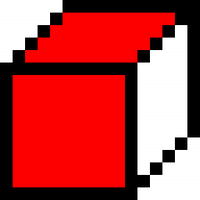
Figure 9-3. An area filled with the bucket fill tool. The black-painted pencil lines form a bounding box, which allows you to fill only parts of the image.
The Eraser Tool
The eraser in GIMP is a basic paint tool. The tool’s preliminary function is to change the pixels color to the background color to simulate an “erasing” effect. By default, the eraser uses a fuzzy shape for painting.
![]() Note Do not confuse the eraser tool with the undo functionality.
Note Do not confuse the eraser tool with the undo functionality.
How to Erase
Please see page 188 if you are unsure how to use the eraser tool.
Drawing with Selections
Basic geometric figures are created with the help of selections in GIMP. Selections can be filled or stroked. Furthermore, selections can be combined as well as divided, which allows drawing composed geometric figures.
Figures are always drawn by creating new selections and filling them with either a foreground or background color. In Figure 9-4, the selection is created (left) with editable borders; it can still be changing in size and shape. Once you are satisfied with the size and shape, create the selection (middle), and fill it with the bucket fill tool (right) and a selected foreground color.
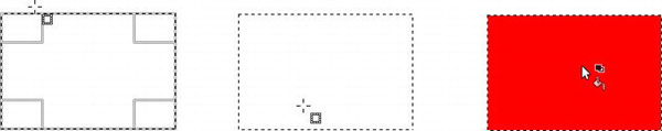
Figure 9-4. The process of drawing with selections (from left to right)
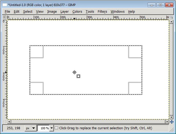
Figure 9-5. The selection is indicated by alternating black and white stripes, which look like marching ants.
Selection Tools
Selections are created with the selection tools, which can be found under Tools ![]() Selection Tools in the image menu. All selection tools provide tool options and their behavior can be adjusted.
Selection Tools in the image menu. All selection tools provide tool options and their behavior can be adjusted.
The following selection tools can be used to create basic geometric figures:
- Rectangle Select
- Ellipse Select
- Free Select (under certain circumstances)
The exercises that follow demonstrate drawing with selections created by the Ellipse Select tool. If you want to create a square selection, the steps are analogous with the Rectangle Select tool.
Creating an Elliptic Selection
Ellipses are created with the help of the Ellipse Select Tool. First, the selections are created and then, depending on what you are after, filled or stroked.
- Create a new image in GIMP.
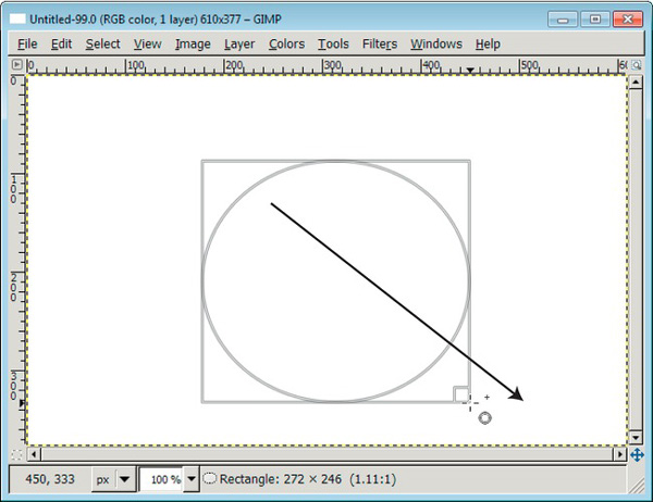
Figure 9-6. An elliptic selection is easily created by drawing an imaginary path (black arrow) by holding the left mouse button.
- Select the Ellipse Select tool in the toolbox or press E.
- Create a new selection by clicking and holding the mouse button while you drag the mouse to either side of the image (see Figure 9-6). A helping square is displayed around the selection. If you are satisfied, click the image again to create the selection. You will now see a selection with “marching ants” surrounding the selection (see Figure 9-7).
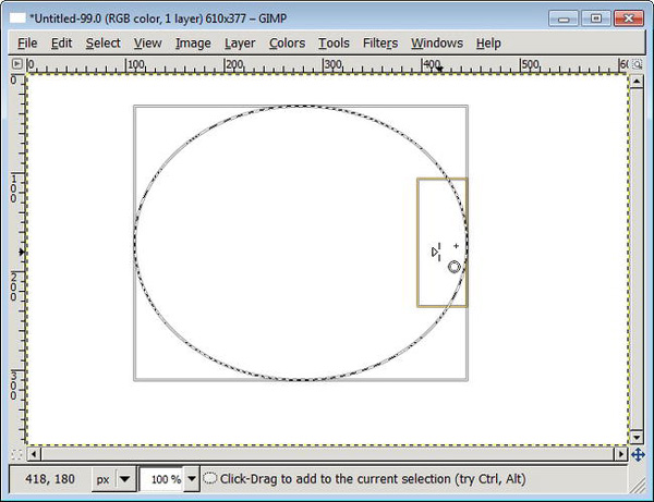
Figure 9-7. Hover your mouse pointer over the edges of the selection to see the helping square.
- To draw an elliptic outline, choose Select
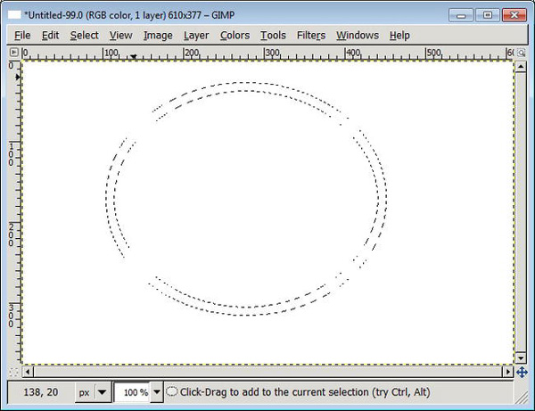
Figure 9-8. A border is easily created around the ellipsis.
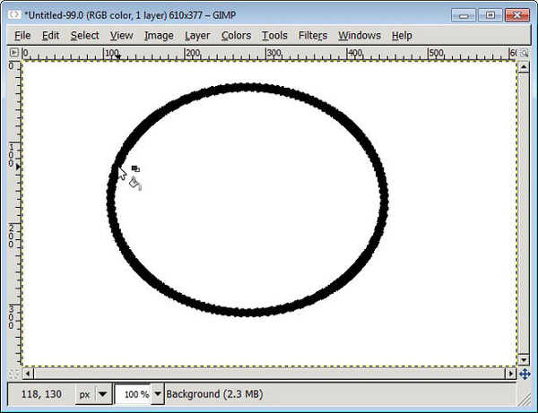
Figure 9-9. Fill the border with the bucket fill tool.
Creating a Circle
Circles are created with elliptic selections. The following exercise alters an elliptic selection into a circle by locking the aspect ratio.
- Create a new elliptic selection with the Ellipse Selection tool described in the section “Create an Elliptic Selection”.
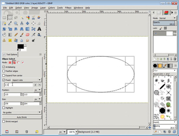
Figure 9-10. By locking in the aspect ratio by 1:1 in the selection tool options, you can create even-sized selections, such as circles.
- Open the tool option dialog of the Ellipse Selection tool. Select the option labeled Fixed:, which should be set to “Aspect ratio” by default.
- Type an aspect ratio of 1:1, as shown in the entry box in Figure 9-11.
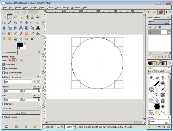
- Resize the elliptic selection by dragging a corner to any direction with your mouse. You created a circular selection (see Figure 9-11).
- Fill the selection by using the bucket fill tool and clicking inside the circled selection (see Figure 9-12).
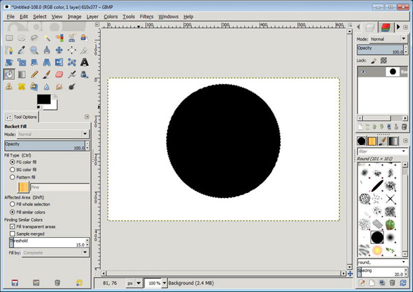
Figure 9-12. Fill the selection by using the bucket fill tool.
Doing More with Selections
Basic selections can be combined with new selections. You can create many different shapes with that in mind.
Selection Modes
Each selection tool can be set to a specific mode. The default mode is set to “Replace the current selection.” This always creates a new selection to avoid confusion.

Figure 9-13. A variety of selection modes illustrated from top to bottom: add, subtract, and intersect. Two circle selections for each mode have been filled.
You will most likely practice with different selection modes in order to create composed geometric objects and to get familiar with the modes benefits. The following exercise will help you start playing with the selection modes.
Creating Composed Forms with Selections
This exercise uses two modes: combine and subtract.
- Create a new image in GIMP.
- Create a new selection, as described in the “Creating a Circle” section.
- Open the tool options for the selection tool by double-clicking on the tool icon in the toolbox.
- Switch the selection mode to “Add to the current selection.”
- Draw a new selection that overlaps the current selection. Create the selection with a single mouse-click (see Figure 9-14).
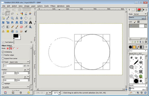
Figure 9-14. Create a new selection next to the first circle to let it overlap.
- Focus on the tool options again. Now you will remove part of the selection by switching the selection mode to “Subtract from the current selection.”
- Draw a new selection that overlaps the current selection (see Figure 9-15).
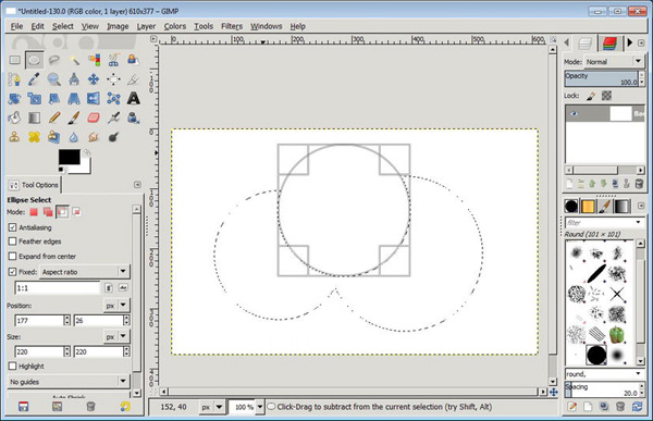
Figure 9-15. In subtract mode, the new selection creates a circular “hole.”
- Create an outline or fill the selection (see Figure 9-16).
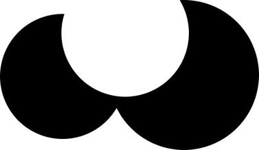
Figure 9-16. Use the bucket fill tool to fill the selection.
![]() Tip Make sure you always reset the selection mode to “Replace the current selection,” because other selection modes may result in undesirable selections in later GIMP sessions.
Tip Make sure you always reset the selection mode to “Replace the current selection,” because other selection modes may result in undesirable selections in later GIMP sessions.
Drawing Freely
GIMP provides helping hands if you are drawing freely to create simple geometric figures.
Drawing a Straight Line
Straight lines can be drawn with any painting tool. As an example, we show you how to draw a straight line by using the pencil.
- Create a new image.
- Choose the pencil or paint tool of your choice. Press N or select Tools
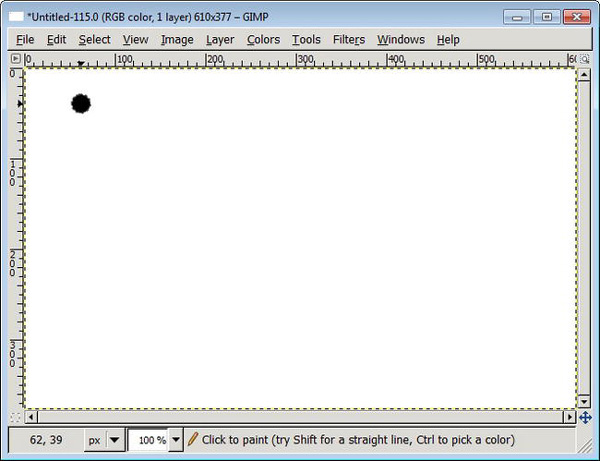
Figure 9-17. A straight line starts with a single point, which you create with a single mouse-click.
- With a single mouse-click, create the first point of the line somewhere on the canvas (see Figure 9-17).
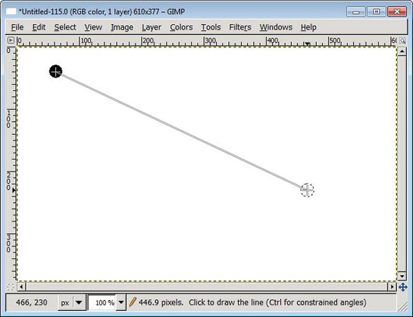
Figure 9-18. While you hold the Shift key, a line connects the mouse pointer and the first point.
- Hold the Shift key while making the second point, which, with a single mouse-click, marks the end of the line (see Figure 9-18 amd Figure 9-19).
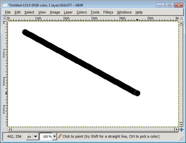
Figure 9-19. A straight line made by holding the Shift key
![]() Tip You can create consecutive line segments by simply continuously creating points with a mouse click on the canvas, while holding the SHIFT key pressed.
Tip You can create consecutive line segments by simply continuously creating points with a mouse click on the canvas, while holding the SHIFT key pressed.
Pixel Art
Chapter 3 introduced the pixel—the smallest element in a digital image. Pixel art is a digital art form using the smallest element in an image. This art originates from the early forms of computer graphics. It was used for icons in operating systems and games. The art form is based on the pixel, which makes it distinguishable from a real-world painting because printouts can look blocky. The art is now used in all kinds of computer application icons. The images can either look flat or mimic a 3D effect, which is called isometric.
What to Avoid
Before creating your first pixel art masterpiece, there is one hint you should follow: avoid creating jagged lines. Pixels placed symmetrically are rendered crisp on your display; the eye picks up misplaced pixels very easily. Lines can look jagged and the image will not look nice (see Figure 9-20).
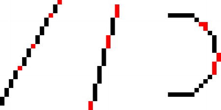
Figure 9-20. Close up, the pixels that compose the lines are not symmetrical (illustrated in red), which will give a jagged or uneven impression from a distance.
What to Draw
Diagonal lines drawn with the same number of pixels look sharper and crisper. Art composed of symmetrical aligned pixels will look nice and crisp (see Figure 9-21).
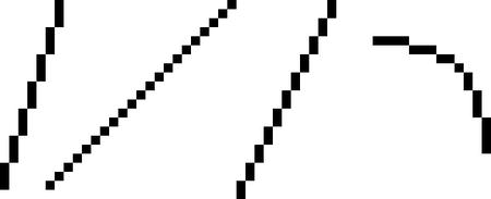
Figure 9-21. If you create diagonal lines, draw the diagonal increment with the same number of pixels.
Using Depth in Pixel Art
Isometric pixel art uses the isometric perspective to create images with depth. Most of these images had a part in early computer games. The images are very small, similar to icons, which allow you to put a lot of detail into the art—making them almost look like toys.
Figure 9-22 illustrates why it is important to arrange pixels symmetric. The image on the left uses symmetric arranged pixels which lead to a very clean and crisp image on the display. The image on the right uses asymmetrically-arranged pixels, which leads to a distorted image.
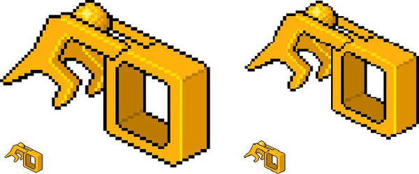
Figure 9-22. Pixel art with depth added to it, also called an isometric view
Drawing a Simple Isometric Box
Drawing a box is the simplest geometric object. Most geometric forms in isometric pixel art use a box as its imaginary base model.
Basically, you create the frame, color the frame, and add highlights and shadows.
- Create a blank, white canvas with File
- Choose the Pencil tool and open the tool options. Verify that the pencil tool size option is set to the lowest setting (1.00) and a Round Brush shape is chosen. Set the Dynamics option to “Dynamics Off” because you need a hard-painting pencil. (The “Size and Shapes” section at the beginning of this chapter can show you how to do that.)
- Because you may use the eraser often, make sure you have set the Eraser tool to the lowest brush size (1.00). With this tool also, set the Dynamics option to “Dynamics Off.”
- Set the zoom level to the highest setting: View
- Choose a black foreground color. (This should be the default.)
- Start drawing a simple square (see Figure 9-23).
Figure 9-23. Start by drawing the front side of the box.
- Create diagonal lines to add depth to the square (see Figure 9-24).
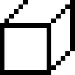
Figure 9-24. If you start with pixel art, draw the diagonal lines pixel by pixel.
The box is now almost finished, but the coloring can make the difference between a dull object and a sophisticated-looking object. You will continue now by adding highlights and shadows to the box.
- Choose a color to fill two sides of the box. Depending on where you imagine the light will come from, leave one box for a darker color—the shadowed part of the box (see Figure 9-25).

Figure 9-25. Fill the sides of the boxes with the bucket fill tool.
- Choose a darker color and fill the final side of the box with this darker color (see Figure 9-26).
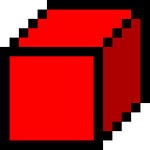
Figure 9-26. One side will be darker to simulate a shadow.
- Choose a lighter color and redraw the inner edge sides. This will make the box look “plastic” (see Figure 9-27).
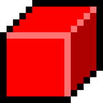
Figure 9-27. Paint the inner edges of the box with a brighter color; this creates a plastic look.
- If you want to make the edges shinier, tip the edge with a very bright, almost white color.
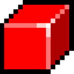
Figure 9-28. To make the corner shiny, use a very bright color that is almost white.
- Set the zoom level to 100% to see the box in a normal size.
Creating a Simple Isometric House
As a final example, we will show you how to create a simple house. You should be able to extend your virtual world from there.
- Create a new image in GIMP.
- Choose the Pencil tool, scale the brush size to the lowest setting (1.00), and make sure you do this with the Eraser tool as well. Choose the highest zoom option. (See the “Drawing a Simple Isometric Box” tutorial to prepare your working area.)
- Create a new transparent layer in the layer dialog. It will help you keep your drawing off the background so that you can paint the background independently (for example, place your house on the moon?)
- Draw the outlines of the house by using two pixels. This will be much like drawing a simple box, depending on the shape of the house.
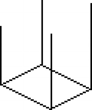
Figure 9-29. Start by drawing the frame of the house.
- Create a new layer. This will be used for drawing the roof. Because the roof will be tilted slightly upwards, you need a layer to toy around with drawing pixels. It will also be easier for you to position the roof on top of the house with the Move tool (see Figure 9-30).
Note Positioning transparent layers with thin lines is tricky because you need to pick the exact position of the line otherwise, the Move tool picks the background layer by default. A high zoom will make this operation easier.
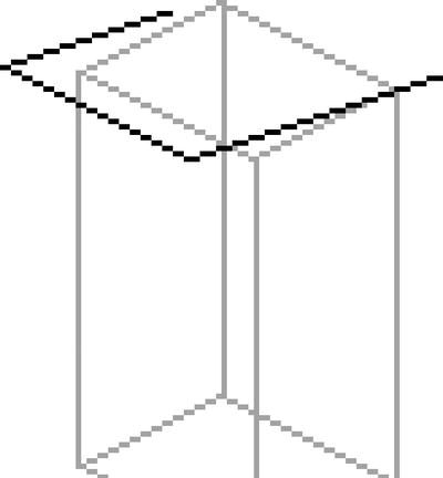
Figure 9-30. Reduce the opacity of the background layer (the box) to assist in positioning the roof correctly while stilling drawing the black pixels for the roof.
- So far we used two pixels for the side lines. Try to use three or four pixels for the roof lines to create the impression of being more angular. Again, this is up to you and what you find looking good (see Figure 9-31).
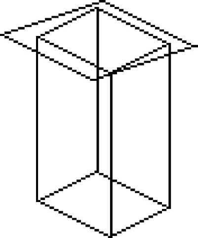
Figure 9-31. The basic structure of the house without coloring
- Use the Move tool to move around the roof in case you need to reposition it. You may still need to make a few adjustments, but you can also do so during or after coloring the image.
Coloring
After you established the outline of the house, you color it and add highlights and shading.
- Choose a color for the house. If you like a house that is made of wood, choose a brownish foreground color.
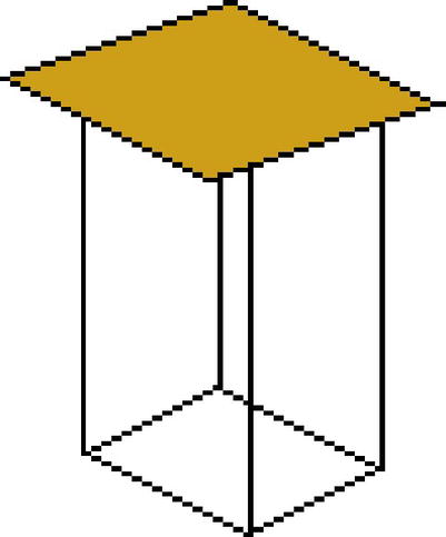
- Start by filling the roof of the house with a color (for example, choose brown for wood). (See Figure 9-32.) Because you have created the roof on its own layer, you can fill the complete roof area without taking care of intersecting lines. Continue by also filling the sides of the house. If the door is shut, also fill the front side with a color.
- Add highlights to draw the wood. Use the Pencil and choose a brighter version of the foreground color. Paint horizontal lines every three or four pixels. Use the straight line technique from “Drawing a Straight Line” (see Figure 9-33).
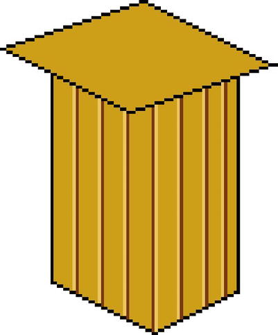
Figure 9-33. Bright and dark lines next to each other simulate depth.
- Choose a darker version of the foreground color and paint straight lines next to the brighter lines. This creates a depth effect.
- Now concentrate on the roof and create the same effect by using a brighter color and a darker color (see Figure 9-34).
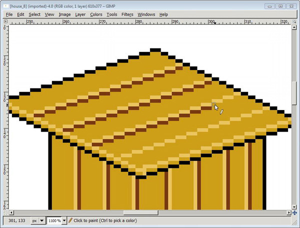
Figure 9-34. Diagonal bright and dark lines on top of the roof
- From here on, you can add little details to finish your picture. Add birds, grass, or whatever you can think of (see Figure 9-35).
Figure 9-35. The finished pixel image with details added
Painting Without a Tablet
Chapter 8 describes how you can use all aspects of your graphics tablet to paint whatever you imagine. You can also do this without a graphics tablet with the help of the Paths tool. It allows stroking lines and emulating paint dynamics, which are usually performed with your free hand.
Assistive Painting: The Paths Tool
The path tool allows you to create smooth curves and complex geometric objects. This makes it the perfect tool for drawing and creating selections for image manipulation.
The advantages of using paths include the following:
- You can create curvy lines, as well as straight lines, like the Pencil tool.
- Selections can be transformed into paths and paths can be transformed into selections. This is needed to fill drawings with a color when created with a path.
- Paths are saved with the GIMP Image Format (XCF) and can therefore be reused when reopening the image. This is a good way to save selections as well.
The paths tool can be selected from the toolbox or by pressing the B key. It has many different modes, which makes it a tool for the moderately advanced user. Every line segment uses handles to bend the line segment in every direction. These lines are called paths or vectors.
Anatomy of a Path
A path line can also be referred to as a path segment because it is not a simple straight line connected by two points. The path uses handles and anchors to create a curve out of a path. Think of it as attaching weights to a wooden plank to make it bend (see Figure 9-36).
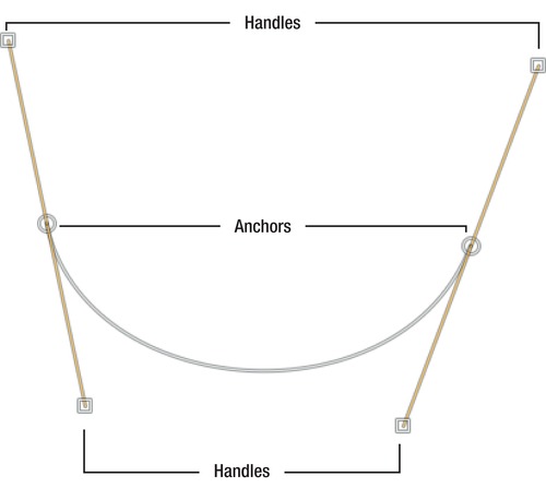
Figure 9-36. An anatomy of a path. The handles on the anchors are used to bend the path by dragging the handles.
Creating a Path Segment
A simple path segment is created similar to a straight line. You create two points and GIMP connects the two points with a path. This exercise does not end by creating a path segment.
The path tool’s primary use is to create curves and stroke them with a paint tool of your choice. Paths can be altered at any time before you stroke the path, which provides a lot of flexibility.
- Create a new image.
- Choose the path tool or simply press B.
- Create a first point with a single mouse-click somewhere in the image.
- Create another point somewhere else in the image to connect the anchor points and to create the line (see Figure 9-37).

Figure 9-37. A path segment created with two anchor points
Creating an S-Curve
An S-Curve is a simple form of a curve, where the two handles of the anchor points face opposite directions.
- Create a new image or use the path from the previous exercise.
- Bisect the line (use your imagination) and move your mouse pointer to the first half of the path.
- Drag the path slowly in one direction, which is illustrated in Figure 9-38. The closer your mouse pointer is to an anchor point, the greater the increase of the curve.
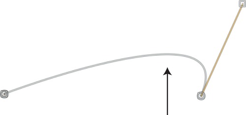
Figure 9-38. Drag the line segment in the direction indicated by the arrow.
- Now do the same with the opposite half of the path segment. Move the segment towards the opposite direction, as shown in Figure 9-39.
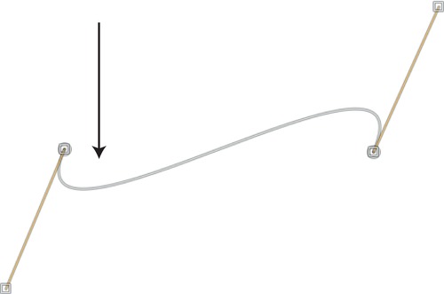
Figure 9-39. To create an S-shape, move the other half of the path in the opposite direction.
- You can now use the handles to shape the line further. Simply click the little squares at the end of the handle and drag them into different positions to see how the handle influences the curve and to get a feeling for the path tool.
Creating an M-Shaped Curve
An M-shaped curve involves a bit more bending of the curve. It uses at least three anchor points and two path segments.
- Create a new image.
- Create two path segments by creating three anchor points (see Figure 9-40).

Figure 9-40. A path with two segments
- Move the entire left path segment upwards, as illustrated in Figure 9-41, by holding your mouse button and moving the mouse forward. You decide which part of the path that you move upwards. Move the path segment in the middle upwards and you will create a nice, circular-shaped path.
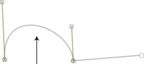
Figure 9-41. Move the entire path segment upwards.
- Move the second path segment upwards, as illustrated in Figure 9-42.
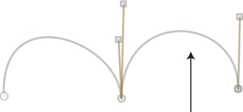
Figure 9-42. The second path segment is moved upward to create an M-shaped path.
Deleting Anchor Points and Path Segments
When creating paths, it may be necessary to delete obsolete anchor points.
Deleting path segments always involves deleting their connecting anchor points, as shown in Figures 9-43 and 9-44. With the anchor points deleted, the corresponding path segment will be removed. Path segments can be easily deleted by selecting an anchor point and by hitting Delete on your keyboard.
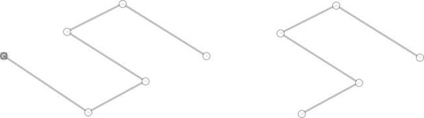
Figure 9-43. If you delete an anchor point on either edge of the path, the path segment connecting the anchor will be deleted.
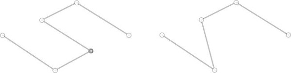
Figure 9-44. If you delete a path segment inside the path, the next anchor point will be used to reconnect the path.
The Path Tool Options
The tool options of the path tool provide three modes affecting path creation, movement, and deletion of anchor points. Each of the modes allows various choices to be made, which makes the tool quite complex.
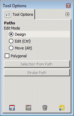
Figure 9-45. The path tool options showing the three edit modes
The following are the three modes of the path tool:
- Design: Adds new anchor points and path segments (the default mode)
- Edit: Allows you to drag handles from anchor points and transform path segments; it also allows you to insert new anchor points in existing path segments
- Move: Allows you to reposition the entire path
Closing a Path
So far, we’ve showed you how to create simple paths. What if you want to draw an object such as an ellipsis or a cube? What if you want to trace a portrait? The path you draw needs to be closed the same way a circle is closed: the end point and start point are merged. This exercise shows you how to created closed paths.
- Create a new image
- Create a new path, which needs to be closed (see Figure 9-46).
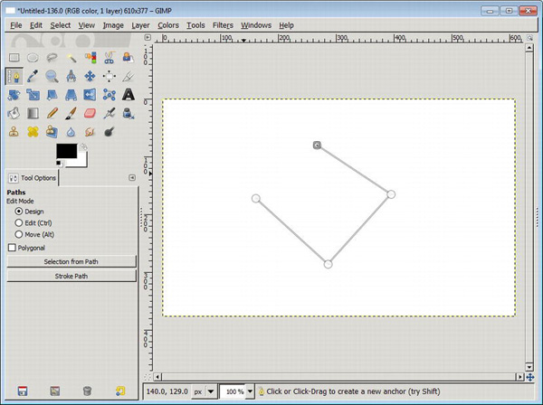
Figure 9-46. A new path is created, which we would like to close.
- Open the tool options of the path tool by double-clicking on the path tool icon in the toolbox or by pressing B.
- Change the path tool to edit mode (see Figure 9-47).
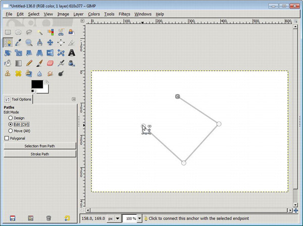
Figure 9-47. The path tool options need to be in edit mode to connect the start and endpoint.
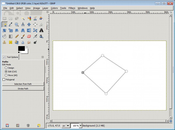
- To close the path click the first anchor point that you created (see Figure 9-48).
Stroking a Path with a Paint Tool
So far, the path is not more than a reference line, which is invisible when you save your picture. Once the path has been created, it is time to stroke it with the paint tool of your choice. By clicking the “Stroke Path” button, which can be found in the path tool options, a Stroke Path dialog appears (see Figure 9-49).
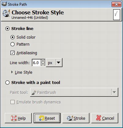
Figure 9-49. The Stroke Path dialog lets you render the paths you created. The options allow you to use any paint tool or a simple line.
This dialog allows you to choose how your path becomes visible; or, in other words, painted on the canvas.
- Create a new image.
- Open the tool options of the path tool by double-clicking on the path tool icon in the toolbox.
- Create a new path and click the Stroke Path button in the path tool options dialog or select Edit
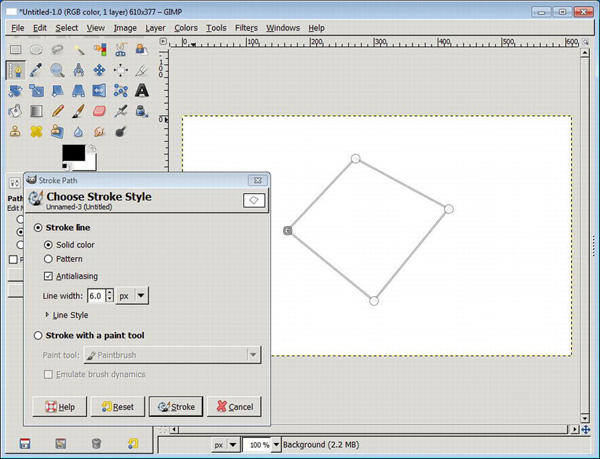
Figure 9-50. Drawing the created path with the Stroke Path dialog is easy because it strokes the paths you created with a normal line style.
- Choose the paint tool you’d like to stroke the path with and click Stroke (see Figure 9-51).
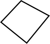
Figure 9-51. After the path has been stroked, the resulting image will look like this illustration.
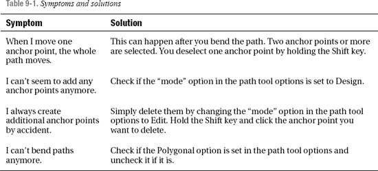
Common Problems with Using Paths
Using paths is a very advanced technique. Table 9-1 lists common pitfalls and how to manage them.
The Paths Dialog
The Paths dialog can be opened by selecting Windows ![]() Dockable Dialogs
Dockable Dialogs ![]() Paths (see Figure 9-52). It provides a way to manage all paths that have been created for the currently opened image. New entries in the dialog are created if you create new paths in your image.
Paths (see Figure 9-52). It provides a way to manage all paths that have been created for the currently opened image. New entries in the dialog are created if you create new paths in your image.
The dialog can also be used to export and import paths to exchange information with vector drawing applications like Inkscape or Adobe Illustrator in a vector file format called SVG.
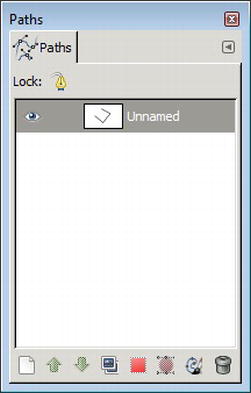
Figure 9-52. The paths dialog, with one unnamed created path in the list
Turning a Selection into a Path
We’ve already shown you in previous sections how to create a selection. Sometimes it can be helpful to save a selection for later use.
- Create a new image in GIMP.
- Create a selection with a selection tool (see Figure 9-53). (If you are unsure follow section “Create an Ellipsis.”)
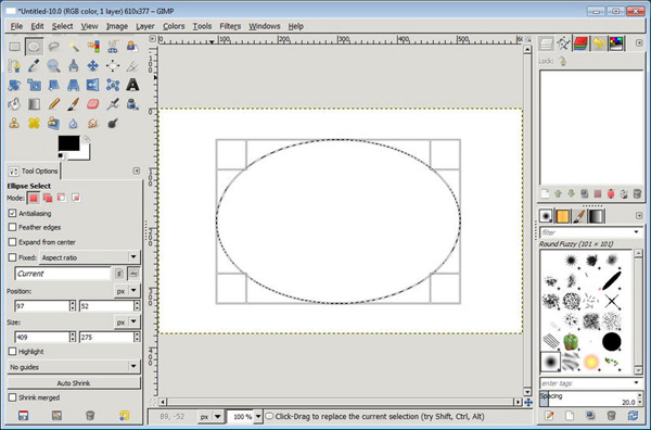
Figure 9-53. An elliptic selection to convert to a path. The right panel shows in the top-left corner of the paths dialog.
- Click Select
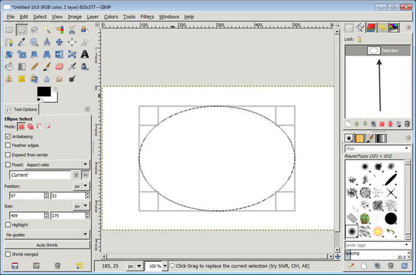
Figure 9-54. The selection still exists, but the paths dialog now shows a new entry (illustrated by the long arrow).
- De-select the selection by clicking Select
- Open the path dialog (Windows
- To stroke this path, focus on the path dialog. Choose the button “Paint along the path” (second button from right), which will bring up the Stroke Path dialog (see Figure 9-55).
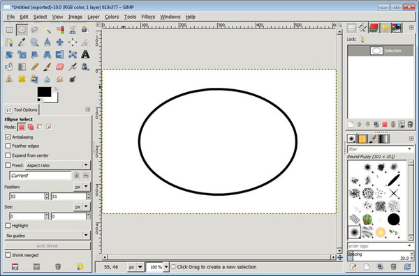
Figure 9-55. The stroked path that was originally created out of a selection
Turning a Path into a Selection
If you like to reuse saved selections from before or like to extract elements from a photo, create the path and transform it into a selection.
- Create a new image in GIMP.
- Create a new path. You don’t have to close the path, which is described in the “Closing a Path” section. If you don’t close the path, GIMP creates the selection from the first anchor point to the end point (see Figure 9-56).

Figure 9-56. Create the path around the object; here it starts at the bottom of the t-shirt.
- Click Select
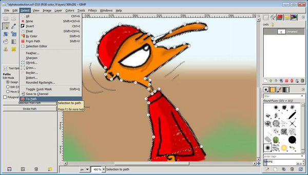
Figure 9-57. Once the path is finished, the selection is easily created.
- Optional: You can now extract part of the image by using Edit
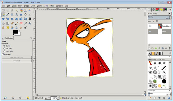
Figure 9-58. The extracted and pasted image as a new layer (the selection was not very precise on the edges of the image)
Extracting Elements from an Image with a Path
The Path tool can become very useful to extract elements from photos. You create a path, transform it into a selection, and copy the image element you want to extract. This method shows a different way of extracting elements. GIMP also provides the Foreground Selection Tool, which can be found in Tools ![]() Selection Tools
Selection Tools ![]() Foreground Select.
Foreground Select.
- Open the image that holds the element you’d like to extract. For this exercise, we will reuse the example image we’ve used in the previous example and refine the selection.
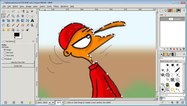
- Create a new path around the object you’d like to select. Focus on creating a rough outline (see Figure 9-59).
- Set the zoom to the maximum, or depending how many anchor points you have set, a zoom level you can comfortably work with. Now customize the path by bending the segments to shape a form around the object you want to extract. Click and hold the mouse button while dragging the segments. Figure 9-60 illustrates this by using arrows.
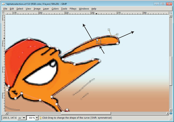
Figure 9-60. Move the paths in the direction you want to bend them.
- For paths segments that form a corner, you can smooth them by holding the Shift key while clicking and dragging the handles in either direction (see Figure 9-61).
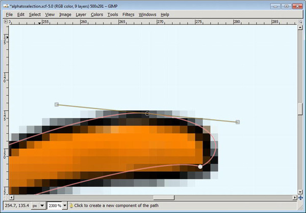
Figure 9-61. Smoothen cornered paths by holding the Shift key while dragging the handles to either side.
- Continue smoothing every part of a path until you are satisfied. If you added another anchor point by mistake, remove the point by changing the path mode to Edit in the paths tool options, hold the Shift key while you click on the point. Make sure you switch back to Design.
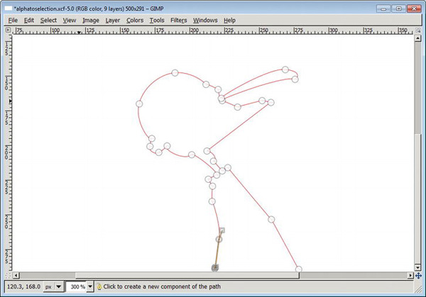
Figure 9-62. The path after it has been “smoothened” manually
- Create a selection by clicking Select
- Extract the element by copying it to the clipboard with Edit
- You can now use your extracted element in a new image by selecting File
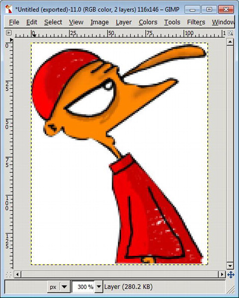
Figure 9-63. The extracted image now looks much better. With paths you have full control and you can readjust and refine the paths to make the extractions even better.
Creating Text That Flows Along a Path
Chapter 6 introduced the text tool to create a web banner. Text usually flows naturally from one direction to the other. But if you are creating invitations or cards to celebrate your child’s birthday, for example, you will need something more out of the line: text that follows a curve, for example. With the path tool, you can create the foundation for the text direction; the path tool provides the text itself. Using them together, you can create interesting word art.
- Create a new image in GIMP.
- Create a new path with two segments. Don’t bend the path for now; concentrate on the basic shape (see Figure 9-64).
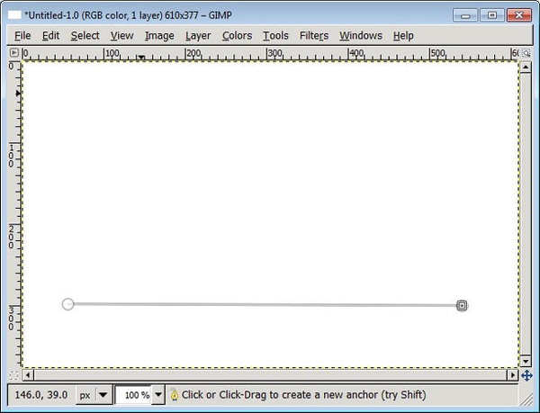
- Bend the path to the shape. Simply drag the path upwards with the mouse to a semicircle shape. The text will later flow over and under the path (see Figure 9-65).
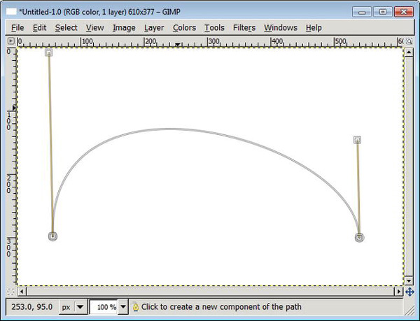
Figure 9-65. After bending the path segment it may not look symmetrical. Fix that by simply pushing one of the helping lines up- or downwards.
- Create a new text layer (as it was introduced in Chapter 6). Mind you, the text should be as long as the path. This is hard to predict, so you will need to cater for a little trial-and-error time (see Figure 9-66).
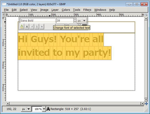
Figure 9-66. After creating the initial text, make it larger (if you need) by selecting the text and changing the text size.
- Once the text is created, select Layer
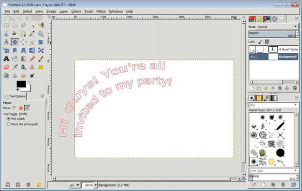
Figure 9-67. GIMP rendered the text along the path and the visibility of the text layer is switched off.
- Check your path dialog and you will see a new path entry. The text rendered along the path is itself a path. This is important, as you still need to render the new text to the layer, otherwise nothing will show up in the printout.
- If your path is not rendered correctly, you may need to remove the path in the path dialog, change the text and re-render it along the path again. If it is rendered out of the image (in the gray area), you may need to move the path into the image (see Figure 9-68). To do that, select the move tool and open the move tool options. By default you will move the layer, but you will want to move the text rendered along the path.
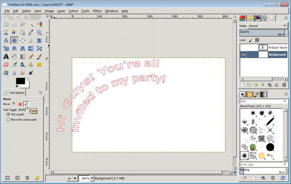
Figure 9-68. The text is rendered over the edges of the image.
- Check the layer dialog. Select the background layer to stroke the text rendered along the path.
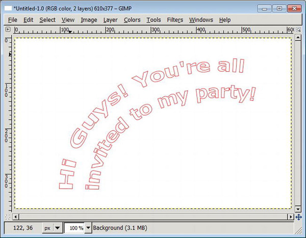
Figure 9-69. The path moved to the middle of the image with the move tool
- Now it is up to you: you can stroke the path with the paint tool and color of your choice as introduced in the “Stroking a Path with a Paint Tool” section (see Figure 9-70). You can also fill the path by creating a selection introduced in the “Creating a Selection from a Path” section (see Figure 9-71).

Figure 9-70. The path stroked with the Stroke Path dialog and a line width of three pixels

Figure 9-71. A selection was created out of the path and filled with a black foreground color.
Summary
This chapter used the toolbox and toolbox options to show you how to draw perfectly straight lines, circles, ellipses and squares. Also how to be creative and change these shapes and how to fill areas with color. You are introduced to the world of drawing tiny pictures in our pixel art section. There is a digital freehand section using the Paths Tool. Finally we show you how to create curving text.