
8
Serial Bluetooth Communication and the micro:bot
Now that we’ve looked at some Bluetooth setup and configuration, let’s explore another way to interact with your micro:bit over Bluetooth—with the UART serial interface. A UART (universal asynchronous receiver/transmitter) is a form of communication via hardware, over a serial connection, in which the data format and transmission speeds are configurable.
This form of communication can sometimes be difficult to set up, but once it’s working it’s the simplest way of sending and receiving messages to your micro:bit board. Since you’re going to want to control your little mobile robot via your board with Bluetooth from your phone, it makes sense to learn about this way of communicating.
UART and Bluetooth
The serial UART Bluetooth interface is not enabled by default, so you’ll need to turn it on and use a few lines of code to configure it. Again, this is beyond what MicroPython, Blocks, and Code Kingdom are capable of, so you’ll need to open up your mbed compiler window again.
Let’s start by cloning the microbit-samples code again like we did in the previous chapter. Right-click on the microbit-samples folder and choose Clone. Name the new folder whatever you like, but as this is testing our UART communications, let’s name it something appropriate. I named mine UART.
Once the cloning process has completed, you have several things to do. You’ll have to change the MicroBitSamples.h file to #define a new variable. You’ll have to write a new .cpp file that compiles and does what you want it to once the new variable has been defined. And finally (and as it turns out, most importantly), you’ll need to update your microbit-dal folder.
As it turns out, the microbit-dal folder that’s included with the microbit-samples code is slightly outdated. It works for most purposes, but the included files don’t declare some important variables—namely MICROBIT_BLE_EVT_CONNECTED and MICROBIT_BLE_EVT_DISCONNECTED. Those variables are used to call functions when particular events (Bluetooth connections and disconnections, as you probably guessed) are detected. In order for these events to be detected correctly (and for your compilations to complete without errors), you must obtain a newer version of microbit-dal and replace the one currently residing in your UART folder. So first, in your current UART folder, right-click the microbit-dal directory (UART/microbit/microbit-dal) and click Delete.
Make sure you’re still signed in to your mbed account. Point your browser to https://developer.mbed.org/teams/Lancaster-University/code/microbit-dal/rev/493dac89f066fd. Just like you did for the microbit-samples application, click the orange Import Into Compiler button on the right side of the page (Figure 8-1).
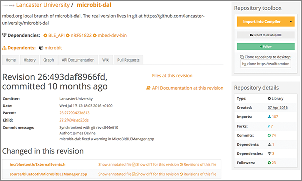
Figure 8-1: Importing a new version of microbit-dal
The Import Library window will open; this is where you tell the compiler where to place the new library. Make sure Library is selected, and make the target path /UART/microbit (Figure 8-2). Then click Import.
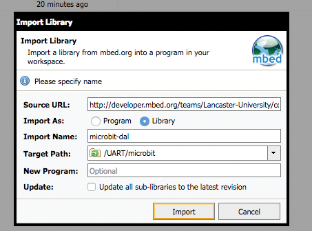
Figure 8-2: Placing the new microbit-dal library
Now that’s done, you can start on the actual code. Open the MicroBitSamples.h file (/UART/source/MicroBitSamples.h). Make sure all of the #defines between lines 38 and 50 are commented out (with a double // in front). Then, before all of them (line 40 or so), add the line
#define MICROBIT_UARTand save the file.
Now, right-click on the source folder and choose New File. Name the new file UART.cpp. Then write the following in the file (we’ll go over this in a moment):
#include "MicroBit.h"
#include "MicroBitSamples.h"
#include "MicroBitUARTService.h"
#ifdef MICROBIT_UART
MicroBit uBit;
MicroBitUARTService *uart;
int connected = 0;
void onConnected(MicroBitEvent e)
{
    uBit.display.scroll("C");
    connected = 1;
    ManagedString eom(":");
    while (1)
    {
        ManagedString msg = uart->readUntil(eom);
        uBit.display.scroll(msg);
    }
}
void onDisconnected(MicroBitEvent e)
{
    uBit.display.scroll("D");
    connected = 0;
}
void onButtonA(MicroBitEvent e)
{
    if (connected == 0)
    {
        uBit.display.scroll("NC");
        return;
    }
    uart->send("YES
");
    uBit.display.scroll("YES");
}
void onButtonB(MicroBitEvent e)
{
    if (connected == 0)
    {
        uBit.display.scroll("NC");
        return;
    }
    uart->send("NO
");
    uBit.display.scroll("NO");
}
void onButtonAB(MicroBitEvent e)
{
    if (connected == 0)
    {
        uBit.display.scroll("NC");
        return;
    }
    uart->send("GOT IT!
");
    uBit.display.scroll("GOT IT!");
}
int main()
{
    uBit.init();
    uBit.messageBus.listen(MICROBIT_ID_BLE, MICROBIT_BLE_EVT_CONNECTED, onConnected);
    uBit.messageBus.listen(MICROBIT_ID_BLE, MICROBIT_BLE_EVT_DISCONNECTED, onDisconnected);
    uBit.messageBus.listen(MICROBIT_ID_BUTTON_A, MICROBIT_BUTTON_EVT_CLICK, onButtonA);
    uBit.messageBus.listen(MICROBIT_ID_BUTTON_B, MICROBIT_BUTTON_EVT_CLICK, onButtonB);
    uBit.messageBus.listen(MICROBIT_ID_BUTTON_AB, MICROBIT_BUTTON_EVT_CLICK, onButtonAB);
    uart = new MicroBitUARTService(*uBit.ble, 32, 32);
    uBit.display.scroll("AVM");
    release_fiber();
}
#endif
So let’s take a look at this code for a moment (you can download the file at https://github.com/wdonat/microbit-code/blob/master/chapter8/UART.cpp). The first two lines you’ve seen before, and the third line, #include "MicroBitUARTService.h", is necessary to start the UART service, since it’s disabled by default.
MicroBit uBit;
MicroBitUARTService *uart;
Then we initialize the MicroBit object and create a pointer to a MicroBitUARTService, uart. This explains the uart-> lines later in the program; uart is a special memory location that points to a collection of functions and variables that all work together, and those functions and variables are accessed using the arrow (->) notation. If you were creating a class and accessing its functions and variables directly, rather than via a pointer, you would use a dot (.) notation instead.
The next two functions, onConnected() and onDisconnected(), dictate what happens when the micro:bit detects an event—namely, MICROBIT_BLE_EVT_CONNECTED and MICROBIT_BLE_EVT_DISCONNECTED that we see in the main function. (You can see why we needed the newer version of the microbit-dal directory—that’s where those two variables are declared and defined.) In the main function, you can see that we’re listening to the messageBus on the micro:bit, and calling those functions when we detect the correct event.
There are two important lines in the onConnected() function regarding the end-of-message (eom) variable. You can see that it’s a ManagedString, that its value is :, and that we call the uart->readUntil() function with it. What this means is that we’re using the colon character (:) as our end-of-message marker, and the micro:bit will read (and display) the message we send until it gets a colon.
The other three functions dictate what happens when we detect a MICROBIT_BUTTON_EVT_CLICK on the messageBus—either Button A, Button B, or both. Obviously, for testing purposes, we’re not doing anything spectacular—just displaying and returning some text.
Open the MicroBitConfig.h file (UART/microbit/microbit-dal/inc/core/MicroBitConfig.h). Again, you’ll need to do a little memory management, since the Bluetooth is such a memory hog. On line 90, set the heap size to 0.50:
#define MICROBIT_NESTED_HEAP_SIZE 0.50A little further down on line 104, make the GATT table a bit smaller:
#define MICROBIT_SD_GATT_TABLE_SIZE 0x300If you’ll recall from Chapter 7, “Using Bluetooth,” the GATT table is where the micro:bit keeps track of Bluetooth services. Since you’re not using all of the available services, you can make it smaller, which has the desirable effect of freeing up some memory for you.
And finally, turn off some services. On line 237, disable the DFU service (this disables on-air programming, which we’re not doing anyhow):
#define MICROBIT_BLE_DFU_SERVICE 0and on line 244, disable event services, since they’re not needed here:
#define MICROBIT_BLE_EVENT_SERVICES 0While we’re in this file, there are two tweaks I make that seem to make Bluetooth development a bit easier. These are completely optional, and your program will work whether or not you try these tweaks. The first thing I do is disable security to make pairing a bit easier. On line 190, set it to 1:
#define MICROBIT_BLE_OPEN 1Then set the no-security transmission power on line 198:
#define MICROBIT_BLE_DEFAULT_TX_POWER 6Finally, I disable the whitelist on line 216 to make pairing easier:
#define MICROBIT_BLE_WHITELIST 0As I said, these last tweaks are optional, but if you’re having trouble pairing it might be worth giving these a try.
When you’ve finished making all of these tweaks, it’s time to compile and save the hex file. Make sure everything has been saved, and then click the arrow on the Compile button and select Compile All. When it’s finished compiling, save the hex file (which should be named UART_NRF51_MICROBIT.hex) to your computer.
You can flash it to your micro:bit right away if you like, but you’ll need something else before you can test it—an app for your smartphone that will allow you to send and receive serial commands over Bluetooth. I don’t have a recommendation here; there are multitudes of possibilities for each platform, but choose a free one. The important thing is that it’s for serial communications, and it’s for both Bluetooth and Bluetooth LE devices (not all apps work with BLE devices). I’m using Serial Bluetooth Terminal by Kai Morich on my Android.
Once you’ve selected an app, install it, pair your phone (or computer) with the micro:bit, and open the application. Make sure the two devices are paired; you may need to tell the particular app you’re using to connect to the micro:bit, though you’ve already paired them. You may need to press the Reset button on your micro:bit as well. Once they’re paired, on your phone or laptop, type a, follow it with the colon (:), and press SEND.
You should immediately see “a” scroll across the micro:bit’s display. Pretty cool, eh? Try typing a word next, like spam, and follow it with a colon. Same result, right?
Okay, now press the B button on your micro:bit. You should see “NO” scroll across the display, and you should also see “NO” appear in the terminal on your smartphone or computer (Figure 8-3).
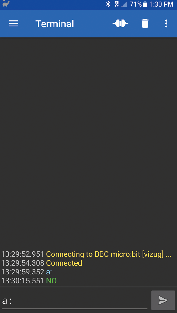
Figure 8-3: Serial communication via Bluetooth
You’ve done it! You’re now successfully communicating back and forth with your micro:bit! As you can probably imagine, it’s only a short step now to communicating with (and controlling) a small mobile robot.
The micro:bot
I feel I should preface this section by letting you know that there is at least one other mobile robot out there called the micro:bot, so this is in no way trademarked, and if you can come up with a better name for it, that’d be awesome.
I should also state here that I did not make the platform on which our robot is based. I do tend to build a lot of robots from scratch, but at some point I realized that I was essentially doing the same thing over and over again. So, in the interest of speeding up the process of creating mobile robots using different parts, I invested in a bot development platform. I chose the Turtle, a 2WD mobile platform from DF Robot (https://www.dfrobot.com/product-65.html—Figure 8-4).
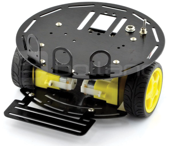
Figure 8-4: The Turtle platform
I do not get any percentages of sales, should you choose to follow my lead; just know that I’ve used this platform for a succession of bots and have never had any problems with it. It comes with two motors and two wheels, a single-pole, single-throw (SPST) switch, and various mounting brackets, connectors, and wire, and only costs about $35. You, of course, are free to choose another platform or to build your own; the important thing here is that you can control your platform using the motor controller board and a Bluetooth-enabled device. Other than that, you’re only limited by your imagination.
Basically you’re going to want your bot platform to have two wheels, each controlled by a different motor. Those motors will be wired to the MOTOR1 and MOTOR2 outputs on the micro:bit’s motor controller board. Then all you have to do is wire a power source to the POWER terminal block on the board and plug in your micro:bit. A separate power source for the micro:bit isn’t necessary, because the motor controller board has an onboard power regulator that delivers the micro:bit’s required 3 volts.
For that reason, however, you may want to wire a switch inline with the power supply (the Turtle platform has one onboard) so that you can easily switch off power to the board—and the micro:bit—without having to unplug wires or remove the :bit.
Your results may vary, but you hopefully will end up with something that resembles Figure 8-5.
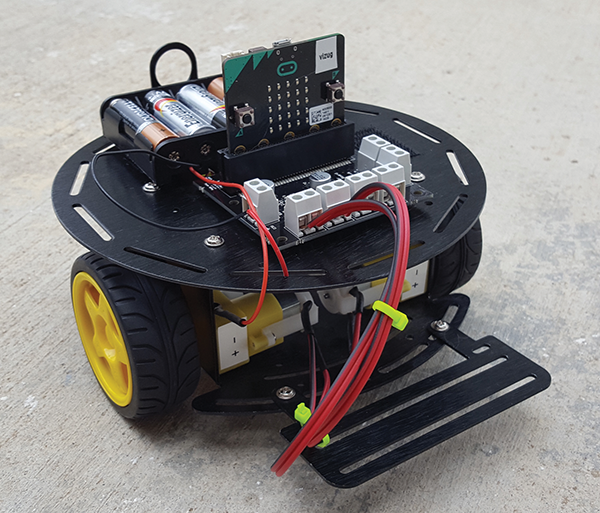
Figure 8-5: Completed micro:bot
Depending on how you’ve wired everything, make sure that you get power to the board when you need it, and then move on to writing the program for your board.
The micro:bot Program
As you can imagine, the program for the micro:bot is going to be very similar to the Bluetooth test code you wrote earlier. However, you’ll be turning pins on and off depending on the values that you send from the phone, and that will determine if the bot goes forward, backward, turns, or stops.
Back in your mbed developer account, to keep things simple, you can just clone the UART program you created earlier. To do so, right-click on the main folder and select Clone. Call the new program buggy and click OK.
Since you’ve cloned a working program, you won’t need to mess with the MicroBitConfig.h file or any of the memory tweaks, since they’re all included in your new cloned file. You will, however, need to fix the MicroBitSamples.h file (buggy/source/MicroBitSamples.h). Open that file, scroll down to the #defines section, and change line 40 to read
#define MICROBIT_BUGGYThen save the file. Now right-click on the UART.cpp file and clone it, calling the new program buggy.cpp. (Make sure you keep the file in the same place in the directory when you clone it; the final file location should be buggy/source/buggy.cpp.) When you’re done, feel free to delete UART.cpp if you would like to keep your workspace clean.
Now let’s edit buggy.cpp. The first thing to change is line 30, the #ifdef line. Change that to read
#ifdef MICROBIT_BUGGYThis tells the compiler to only compile this .cpp file if MICROBIT_BUGGY is defined in MicroBitSamples.h.
Now let’s declare some pins. Delete the line
int connected = 0;(let’s assume you’re always connected, since it just won’t work otherwise) and add
int pin12, pin8, pin16, pin0 = 0;These are the pins that are hardwired to the MOTOR1 and MOTOR2 terminal blocks on the motor controller board.
The onDisconnected() function you’ll leave alone—it works just fine for our purposes. You do need to tweak the onConnected() function, however. Change the while() loop to read as follows:
while(1)
{
    ManagedString msg = uart->read(1);
    moveBot(msg);
}
and remove the line
ManagedString eom(":");What this now does is read just one character from the serial stream, and then it calls the moveBot() function (which we’ll show you how to write in a moment) with that one character. This way, you can type a on your serial terminal and the moveBot() function will immediately be called with a as soon as you hit Send on your device. You don’t have to type a delimiter like the colon.
In case you’re familiar with C and C++ and are wondering just what the heck a ManagedString is, it’s the micro:bit’s answer to C’s character array (char[]) and C++’s string types. The ManagedString is a managed type that releases memory as needed—no garbage collection necessary—and is less prone to bugs by inexperienced programmers. It can be constructed in several different ways, it can be manipulated (concatenated, chopped up, etc.), and you can even use operators like +, =, ==, and < and > with it.
OK, back to the program. Let’s write the function that does all the work—moveBot().
void moveBot(ManagedString message)
{
    ManagedString w("w");
    ManagedString space(" ");
    ManagedString a("a");
    ManagedString d("ad");
    ManagedString s("s");
    if (message == w) // start moving
    {
        pin12 = 1;
        pin16 = 1;
        drive = 1;
    }
    else
    {
        if (message == space) // all stop
        {
            pin12 = 0;
            pin16 = 0;
            drive = 0;
        }
    }
    if (drive == 1)
    {
        if (message == a) // left
        {
            pin12 = 1;
            pin16 = 0;
        }
        else
        {
            if (message == d) // right
            {
                pin12 = 0;
                pin16 = 1;
            }
            else
            {
                if (message == s) // stop going left or right
                {
                    pin12 = 1;
                    pin16 = 1;
                }
                else
                {
                }
            }
        }
    }
    uBit.io.P0.setDigitalValue(pin0);
    uBit.io.P8.setDigitalValue(pin8);
    uBit.io.P12.setDigitalValue(pin12);
    uBit.io.P16.setDigitalValue(pin16);
    return;
}
This function is pretty self-explanatory, I think, despite the nested if/else statements. You compare the strings received, and depending on what they are, you send the bot in a specific direction. When you’re finished, the final buggy.cpp should look like this:
#include "MicroBit.h"
#include "MicroBitSamples.h"
#include "MicroBitUARTService.h"
#ifdef MICROBIT_BUGGY
MicroBit uBit;
MicroBitUARTService *uart;
int pin0, pin8, pin12, pin16 = 0;
int connected = 0;
int drive = 0;
void moveBot(ManagedString message)
{
          ManagedString w("w");
          ManagedString space(" ");
          ManagedString a("a");
          ManagedString d("d");
          ManagedString s("s");

  if (message == w) // start moving
  {
      pin12 = 1;
      pin16 = 1;
      drive = 1;
  }
  else
  {
      if (message == space) // all stop
      {
        pin12 = 0;
        pin16 = 0;
        drive = 0;
      }
  }
  if (drive == 1)
  {
      if (message == a) // left
      {
        pin12 = 1;
        pin16 = 0;
      }
      else
      {
        if (message == d) // right
        {
          pin12 = 0;
          pin16 = 1;
        }
        else
        {
          if (message == s) // stop moving left or right
          {
            pin12 = 1;
            pin16 = 1;
          }
          else
          {
          }
        }
      }
  }
  uBit.io.P0.setDigitalValue(pin0);
  uBit.io.P8.setDigitalValue(pin8);
  uBit.io.P12.setDigitalValue(pin12);
  uBit.io.P16.setDigitalValue(pin16);
  return;
}
void onConnected(MicroBitEvent e)
{
      uBit.display.scroll("C");
      connected = 1;
      while(1)
      {
          ManagedString msg = uart->read(1);
          moveBot(msg);
      }
}
void onDisconnected(MicroBitEvent e)
{
      uBit.display.scroll("D");
      connected = 0;
}
int main()
{
      // Initialize the micro:bit runtime.
      uBit.init();
      uBit.messageBus.listen(MICROBIT_ID_BLE, MICROBIT_BLE_EVT_CONNECTED, onConnected);
      uBit.messageBus.listen(MICROBIT_ID_BLE, MICROBIT_BLE_EVT_DISCONNECTED, onDisconnected);
      uart = new MicroBitUARTService(*uBit.ble, 32, 32);
      uBit.display.scroll("BUGGY!");
      // If main exits, there may still be other fibers
      // running or registered event handlers etc.
      // Simply release this fiber, which will mean
      // we enter the scheduler. Worse case, we
      // then sit in the idle task forever, in a
      // power-efficient sleep.
      release_fiber();
}
#endif
Save the program, compile it, and flash the hex file to your micro:bit. You can download the file at https://github.com/wdonat/microbit-code/blob/master/chapter8/buggy.cpp. Once it’s loaded, pair your phone with the micro:bit and bring up the Bluetooth serial terminal app you installed. After you connect to your board, type (and send) w. Your bot should shoot across the room. If you need it to stop, send a space; sending a and d should make it turn left and right, respectively. (If your bot turns right when you type a and left when you type d, it simply means that you’ve reversed your connections from the motors going to your motor board. Just swap the wires.) If it’s turning in a circle, sending an s will make it stop turning and resume going forward. Again, a space will make it come to a full stop no matter what it’s doing.
Now, granted, this is not particularly elegant code. Without writing a smartphone app, we’re reduced to communicating with the micro:bit with a serial connection, sending characters one at a time. I tried to borrow from the typical video game keys, using w, a, s, and d, but I’ll admit it can be tricky to get the hang of typing w and hitting Send and then a and hitting Send and then s and hitting Send quickly in succession in order to get the bot to turn a corner and keep going. It can be done, of course; my dog is now a highly trained bot chaser.
If you have experience with writing apps for your particular platform, I encourage you to write a more graphical interface for your bot. The micro:bit Blue app I mentioned earlier that is currently Android-only has a gamepad screen that can be used with a program very similar to ours to control the bot. You can find that program here: https://lancaster-university.github.io/microbit-docs/ble/event-service/. I thought it was important, however, that you first learned about the guts of Bluetooth serial communication, and of course there’s the small problem that if you own an iPhone, the gamepad interface will be unavailable to you.
That concludes our introductory exploration of the micro:bit platform. If you want to get deeper into programming the board, particularly in C/C++, I highly recommend visiting https://lancaster-university.github.io/microbit-docs/. The documentation there of the micro:bit runtime is exhaustingly thorough; all you’ll ever need to know about all possible classes, functions, types, and so on can be found there. If you still prefer Python and the other languages, I encourage you to stay abreast of changes; the micro:bit environment is new and is changing quickly. Either way, keep learning and building, and I look forward to seeing what you come up with!