
6
Interfacing with the GPIO Pins
Now that you’re familiar with the micro:bit board and its onboard parts, we’ll look at interfacing with the GPIO pins on the edge of the board. There are several ways to connect to them, the most basic way involving alligator clips and banana plugs.
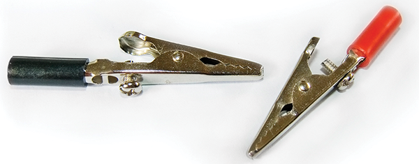
Figure 6-1: Alligator clips
As you’ve probably noticed, several of the pins on the edge of the micro:bit are both larger than the other pins and are also connected to holes in the board. This enables you to attach either alligator clips (Figure 6-1) or banana plugs (Figure 6-2) to the board for basic interaction. I won’t go into the specifics—readers are more than likely acquainted with these basic interfaces. Just be aware that if you don’t have any add-on parts or additional breakout boards, you can use these simple parts to do some cool things with your board. All of the functions I discuss in the following sections will work no matter how you connect to the board’s GPIO pins. However, I imagine you’ll want to add to the basic functionality made possible with clips and plugs, so read on.
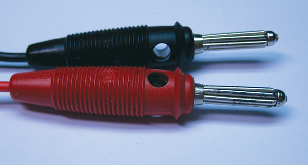
Figure 6-2: Banana plugs
The GPIO Pins and the Edge Connector Breakout Board
When you’ve worn out the novelty of basic connectivity, I think it’s time to take a look at extending the board’s capabilities with some add-on parts. I’d like to introduce you to the edge connector breakout board.
I mentioned this board briefly in the beginning of the book. It’s available from several online retailers, and should cost you less than $10, including shipping. It has a slot on the side into which you slide your micro:bit board, and it maps all of the “pins” on the edge of the board to actual GPIO headers to which you can attach jumper wires (Figure 6-3). Note the position of the board in the figure—the front of the board faces up, in the same direction as the GPIO pins. It is important to know that for the edge connector board as well as for the motor controller board, the orientation of the board is not important when it comes to accessing the pins. The pins are paired; both headers in column 3, for instance, access pin 3 on the board, no matter which direction the board is facing.
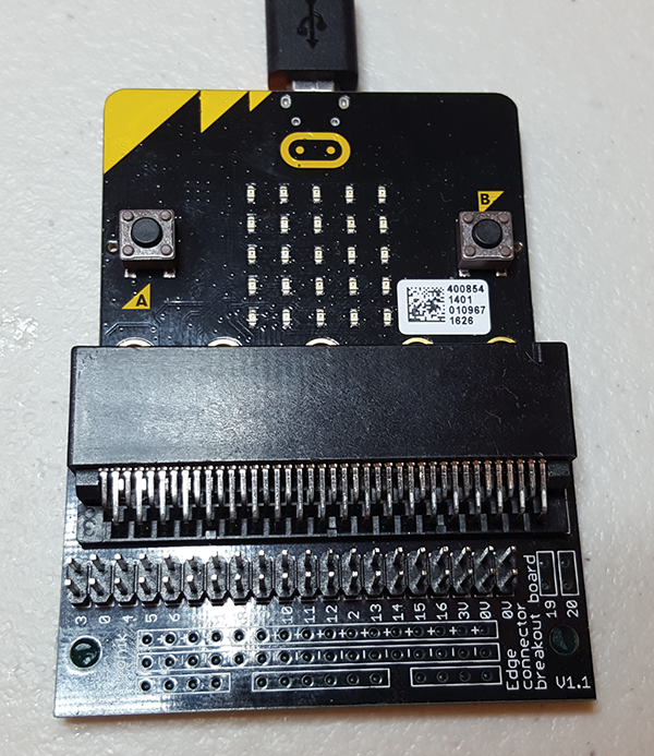
Figure 6-3: micro:bit inserted into edge connector board
It’s also worth noting that the rows of pins, although in the same order as the pins on the edge of the board, do not follow a numerical sequence—it doesn’t start with row 0, followed by row 1, 2, 3, and so on. Rather, the first pair is referred to in code as pin3, the second as pin0, and so on. See Table 6-1.
Table 6-1: GPIO header pin descriptions
| Row label | Name | Description |
| 20 | SDA | I2C SDA—magnetometer/accelerometer (unsoldered) |
| 19 | SCL | I2C SCL—magnetometer/accelerometer (unsoldered) |
| 0V | 0V | GND |
| 0V | 0V | GND |
| 3V | 3V | 3V |
| 16 | DIO | Gen. purpose |
| 15 | MOSI | Serial—Master Out/Slave In |
| 14 | MISO | Serial—Master In/Slave Out |
| 13 | SCK | Serial—Clock |
| 2 | PAD2 | Gen. purpose |
| 12 | DIO | Gen. purpose |
| 11 | BTN_B | Button B—goes low on press |
| 10 | COL3 | LED matrix column 3 |
| 9 | COL7 | LED matrix column 7 |
| 8 | DIO | Gen. purpose |
| 1 | PAD1 | Gen. purpose |
| 7 | COL8 | LED matrix column 8 |
| 6 | COL9 | LED matrix column 9 |
| 5 | BTN_A | Button A—goes low on press |
| 4 | COL2 | LED matrix column 2 |
| 0 | PAD0 | Gen. purpose |
| 3 | COL1 | LED matrix column 1 |
In front of the header pins, at the very edge of the board, is an area that has been set aside for prototyping, with a positive (3V) rail, a GND rail, and some unconnected pads that can be attached to whatever you like. This makes it easy to connect switches or additional sensors, particularly if you decide to solder some additional header pins to these pads. If you plan on using I2C in your projects at all, I highly recommend soldering some headers to pins 19 and 20. Those two pins are located at the end of the row of headers, rather than inside the prototyping area.
To give a quick introduction to accessing the pins in code, let’s go ahead and attach a multimeter to some pins and see what happens in real time as we send commands. Grab a multimeter and set it to either Automatic (if you have a meter that supports it) or DC 1.5V. Attach an M/F jumper wire to pin 0 (the second pin from the left) and another M/F wire to the last GND pin on the right. Attach your multimeter positive and negative leads to those wires. Make sure your micro:bit board is attached to your computer’s USB port so you can both power your board and flash programs to it.
Now, on your computer, open up mu, start a new sketch, and press the REPL button to enter an interactive session with your board. Watch your multimeter screen as you type the following:
>>> pin0.write_digital(1)Then press Enter/Return. You should get a reading of about 3.23V (Figure 6-4).
Now type:
>>> pin0.write_digital(0)
Figure 6-4: Turning on pin 0
and press Enter/Return. Your multimeter should read 0V again. If you repeat this experiment—turning on a pin and measuring the voltage—with pin 8, for instance, you should get identical results. You’re basically turning those pins on and off by sending digital 1’s and 0’s to them. Obviously, this can be done within a script as easily as it can be done interactively.
Now hook up your positive jumper wire to pin 5 (the pin for Button A). Your multimeter should read about 3.23V. Press the A button, however, and the voltage should immediately drop to zero, just as it says in the chart. You can repeat the experiment with pin 11 and Button B.
analog_read() and analog_write()
Now that you’ve used write_digital(), let’s take a look at read_analog() and write_analog(). These functions allow you to read the value of an analog device, like a potentiometer, for example, or to output an analog value rather than a simple digital 1 or 0. There’s an easy way to display that value as well—by using an LED hooked up to another pin.
For this experiment, you’ll need a potentiometer and an LED. Any color LED will work, so just grab whatever you’ve got lying around. If you don’t have an extra LED lying around, go find/buy/get one, and resolve to never be without a spare LED in your workshop again.
Using jumper wires, connect the pot’s GND post (if the pot’s shaft is pointing toward the ceiling and the pins are facing you, the GND pin is normally the pin on the left) to one of the micro:bit’s GND pins. Connect the pot’s input pin (either the middle pin or the one on the right, depending on the pot) to pin 1 on the edge connector board. Connect the other unused pin on the potentiometer to the micro:bit’s 3V pin. Finally, connect an LED to the micro:bit’s GND pin and pin 2. Everything should look like it does in Figure 6-5.

Figure 6-5: Diagram of LED/potentiometer setup
Start a new sketch in mu and enter the following code:
Now type:
>>> pin0.write_digital(0)
from microbit import *
pin2.write_analog(0)
while True:
    pin2.write_analog(pin1.read_analog())
Flash the sketch to your micro:bit.
Assuming you’ve got everything wired correctly, your LED should immediately light up, though it may be rather dim depending on your potentiometer’s position. Play around with the pot’s setting, and you should see the LED change brightness depending on the position of the pot.
Looking at the script, it should be pretty self-evident what’s going on here. We start writing a 0 to pin 2 to make sure it’s completely off. Then we read the value of the potentiometer (or the voltage it’s passing, to be technically correct) and send that voltage to the LED. The more voltage the pot is passing, the brighter the LED.
If you’re interested in the actual values being emitted by the potentiometer, you can try the following script:
from microbit import *
while True:
    text = str(pin1.read_analog())
    display.scroll(text)
    sleep(500)
For this script, remove the LED from the circuit. Connect the pot’s ground pin to the micro:bit’s GND pin, the pot’s input pin to pin 1, and the pot’s other pin to the micro:bit’s 3V pin (Figure 6-6.) When you flash the script to your board, it will display the pot’s current value every half second. The micro:bit has a 10-bit analog-to-digital converter on board, so you should see values ranging from around zero all the way to 1023 at the other end of the pot’s travel.
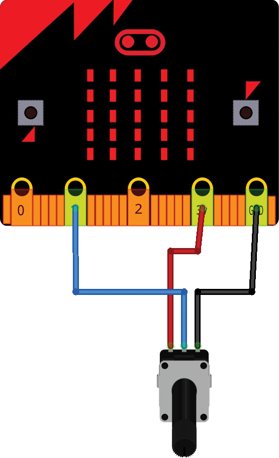
Figure 6-6: Reading the potentiometer’s value
Now that we’ve looked at read_analog(), write_analog(), and write_digital(), there’s one more function in that group we should investigate—read_digital(). Just as you’d suspect, this function is what you’ll use to read from sensors such as switches that send a simple ON/OFF signal to the board. If you happen to have an old switch lying around, it’s a perfect way to test read_digital(). If not, you’ll just have to trust me on this one. Hook up a simple single-pole, single-throw (SPST) toggle switch to pin 16 and one of the 3V pins. With the switch open, typing
>>> pin16.read_digital()on the mu REPL command line should return 0. Running the same command with the switch closed will return a 1. Quite simple. In the same vein, the is_touched() function is interesting. You don’t need a switch to play with this one, as your body acts like a switch. Connect one of your jumper wires to pin 1 and the other to a GND pin. If you hold both wires in your hand,
>>> pin1.is_touched()will return a 1, whereas leaving one wire untouched will return a 0. Connecting the pin to ground (through your body) sets the return value to 1.
I2C
One of the things that hobbyists may find attractive about the micro:bit is its I2C capabilities. Pins 19 and 20, though not immediately available without soldering some headers to them, allow you to control and read from I2C devices, which can be very helpful when you’re attaching various sensors and devices. Having a preprogrammed way of interacting with large numbers of add-ons can greatly simplify your life.
To use the I2C interface with the micro:bit’s breakout board, you’ll need to solder some headers to pins 19 and 20. As you remember from Table 6-1, pin 19 is the clock line (SCL) and pin 20 is the data line (SDA). You can daisy-chain your devices just as you normally would, and then the functions i2c.write() and i2c.read() allow you to communicate with and control them from your board. You don’t need to specify a pin when you call these functions, since pin 20 is hard-coded to read and write I2C data, and the micro:bit’s firmware automatically takes care of the timing for you with pin 19—the SCL (clock signal) pin.
This brings up another helpful hint for you: if you’re not sure what functions are available for each pin (not all pins support read_analog() and write_analog(), for instance) you can type the pin number in your mu REPL window, followed by a period and the Tab key, and you’ll see a list of all functions that are available to that pin (Figure 6-7.)
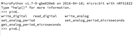
Figure 6-7: List of available functions for pin 6
If you type i2c.write( (no closing parenthesis) and press Tab, you’ll see all the possible parameters for the i2c_write() function. You’ll notice that pin numbers are allowed, but that’s not for reading and writing I2C values; rather, those parameters are available should you want to write the value of pin2.read_analog(), for example.
The Motor Driver Board
Now that you’re familiar with ways to access your board’s GPIO pins, let’s talk about possibly the coolest way of interacting with your board’s pins: with a motor controller board, which I mentioned in the first chapter. We’ll be using that board for the micro:bot in a later chapter, so let’s see how we can interact with it. (See what I did there? The micro:bot is a play on words, and that’s also what we literary types refer to as foreshadowing. Stay tuned!)
The motor controller board has a slot into which you’ll plug your micro:bit, a row of pads on the edge corresponding to all of the micro:bit’s pins (so you can attach more stuff even when the board’s plugged in), and seven block terminals. These terminals allow you to connect an external power supply (essential for driving motors, since the micro:bit can’t source much current), and connect to two different motors (such as a left drive wheel and a right drive wheel). You can also connect two separate input devices that will be hardwired to pins 1 and 2, and you can also connect an external device to the button_a and button_b inputs to be read by the micro:bit.
To use the motor controller board, plug your micro:bit into the slot. The board is designed so that the micro:bit board may be facing either way; however, in order to use the extra row of headers on the edge of the board, the LED array will need to face that edge (Figure 6-5). For our testing purposes here, it doesn’t matter which way you plug it in.
Now plug in a power supply. The screen printing on the controller board suggests between 4.5V and 6V, so try a pack of 3 or 4 AA batteries. The maximum recommended voltage is 6 volts, so please don’t blame me if you plug in a car battery and either your motor controller board or your micro:bit releases a puff of smoke!
Finally, plug in two jumper wires to the MOTOR1 terminal block. Connect these to your multimeter, using either the AUTO setting or the 1.5V DC setting as we did before. Your final setup should look like Figure 6-8.

Figure 6-8: Testing setup for motor control board
As with most motor controller boards, we control the motors by alternating the signals sent to the motor terminals. MOTOR1 is controlled with pins 8 and 12 on the micro:bit, and MOTOR2 is controlled with pins 0 and 16. Table 6-2 shows the motor behavior associated with different pin values; remember that Forward and Reverse are relative and depend on how the motor is connected in the first place.
Table 6-2: Pin values and motor directions
| P8 | P12 | MOTOR1 | P0 | P16 | MOTOR2 |
| 0 | 0 | coast | 0 | 0 | coast |
| 1 | 0 | forward | 1 | 1 | forward |
| 1 | 1 | brake | 1 | 1 | brake |
| 0 | 1 | reverse | 0 | 1 | reverse |
To illustrate this, our multimeter will show us voltages as we change pin values around. In your mu window, start a new Python script and enter the following:
from microbit import *
while True:
    # Reverse
    pin12.write_digital(1)
    pin8.write_digital(0)
    sleep(2000)
    # Coast
    pin12.write_digital(0)
    sleep(2000)
    # Forward
    pin8.write_digital(1)
    sleep(2000)
    # Brake
    pin12.write_digital(1)
    sleep(2000)
Flash this code to your micro:bit and watch the display on your multimeter. It should start switching between your connected voltage, zero, and a negative voltage, about two seconds apart. I’m using 5 AA batteries in the setup shown in Figure 6-5, so my meter shows 7.2V, 0V, –7.2V, 0V, and so on. When the voltage is positive, a connected motor will be spinning in one direction, and when it’s negative the motor will spin in the opposite direction.
As I’ve mentioned before, two of the terminal blocks on the board give you access to the button pins; in other words, sending voltage to those blocks has the same effect as pushing the buttons on the micro:bit board. To illustrate that, keep the same setup described earlier, and connect an additional set of jumper wires to the terminal block for Button A. You don’t have to connect any voltage source—pressing the buttons just sends them to ground.
In a new mu script, enter the following:
from microbit import *
while True:
    pin12.write_digital(0)
    pin8.write_digital(0)
    if button_a.is_pressed():
        pin12.write_digital(1)
        pin8.write_digital(0)
    else:
        pin12.write_digital(0)
        pin8.write_digital(1)
Flash this code to your board. When it’s running, at first your multimeter should be displaying a negative voltage. When you touch the two jumper wires together, however, the voltage should immediately become positive. To double-check that it’s the same as pressing the button, try pressing the actual Button A on the micro:bit—the results should be the same.
Finally, to try out the input terminal blocks, connect the same two jumper wires to the INPUT2 block and flash this code to your micro:bit:
from microbit import *
while True:
    pin12.write_digital(0
    pin8.write_digital(0)
    if pin2.is_touched():
        pin12.write_digital(1)
        pin8.write_digital(0)
Now your multimeter should read around 0V unless you touch the INPUT2 wires together. At that point, you should see a negative value on the meter, which then goes away when you release the wires.
You can also substitute if pin2.read_digital() == 1: for the if statement in your code, but I’ve found that unless you have fresh batteries that deliver at least 3V, the pin will never read 1. For that reason, I’m not particularly fond of the read_digital() function and would rather use either is_touched() or read_analog() and use the value of a pot to determine an input as a parameter value.
So that’s an introduction to accessing the GPIO pins on the micro:bit. There are additional functions that I didn’t go into here, but this should give you a basic idea of what’s possible, with either the edge connector board or the motor controller board. In the next chapter I’ll show you how to use Bluetooth and the onboard radio to communicate with your board, all in preparation for the projects in Chapter 8.