
2
A Tour of the micro:bit
Now that you’ve had a quick introduction to what the micro:bit is and what it can do, it’s time to take a look at this impressive little device and see what’s packed onto its small surface (4.5 × 5 cm—it’s been billed by the BBC as being about half the size of a credit card). I usually introduce new users to a device like this by examining each component one by one, moving clockwise around the board, and that seems like a perfectly reasonable route to take now. I’ll refer to the side of the micro:bit with the USB power connector and the micro:bit logo as the back, and the side with the array of LEDs and the two push buttons as the front (Figures 2-1 and 2-2).
Starting at the top (12 o’clock position) on the back, we have a standard USB micro port (not a USB mini port). When you connect the micro:bit to your computer, the port is used both to power the board and for data transfer from your computer. The board requires 3.3V to operate. USB offers around 5V, so a regulator is used to lower the input voltage to a level that the board can use when it’s being powered by your computer.

Figure 2-1: Back of the micro:bit
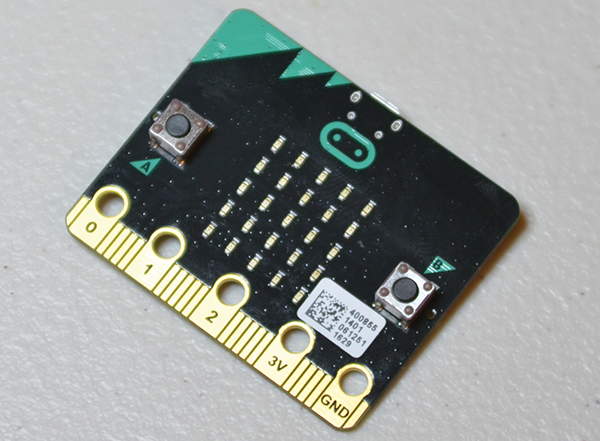
Figure 2-2: Front of the micro:bit
Keep in mind, however, that this port is not necessary for either power or data transfer. You can power the micro:bit with a battery pack, and you can load programs to the board (also called flashing the board) by way of Bluetooth and a Bluetooth-enabled device such as a smartphone or laptop. This can come in handy if you install your micro:bit in an inaccessible place such as a project box or buried deep inside a load of electronics and wiring; you can flash the board with a new program by merely coming within a few feet of it. We’ll go over Bluetooth connectivity and flashing in Chapter 3, “Programming Using MicroPython,” and Chapter 7, “Bluetooth.”
Just next to the USB port, before the push button, is a small yellow LED that you probably wouldn’t notice until you plug the unit into your computer. It’s a status LED, and its purpose is simply to let the user know that the micro:bit is doing something, whether it’s loading a program or sending data.
Next to the USB port and the status LED is a momentary push button that serves as the reset button. When the board has a program onboard and is executing it, pushing this button resets it to the start of that program, as if the board had been powered off and then on again. This button is not programmable by the user; it’s hard-coded as a reset button only. If you’ve played around with an Arduino, you’re familiar with the concept of this button and what it’s used for. It’s helpful if your board freezes, if you need to restart a program for any reason, or if you just need to reset the board to a last-known-good configuration.
Next to the reset button is another power port. This port has two pins and is where you’ll plug in an external power source if you’re not powering the device via USB. The basic device comes with a battery pack that holds two AAA batteries; the Molex female connector to that pack plugs into the male pins on this connector.
Continuing in a clockwise direction, you’ll see a small black integrated circuit (IC) set back a bit from the edge of the board (Figure 2-3). This is the USB controller that allows the CPU to communicate with the USB port. It’s an ARM Cortex-M0+ chip that not only allows the USB communication to take place, it also regulates the 5V power from the USB port down to the 3.3V, which the micro:bit needs to operate. The regulator portion of the chip isn’t necessary or used if you’re powering your board with batteries.
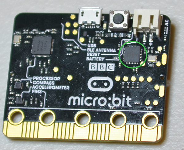
Figure 2-3: The USB microcontroller
Now we come to the bottom of the board and its piano-key-like appearance. Each of these twenty-five individual metal-plated “stripes” is a general-purpose input/output (GPIO) pin, which can be accessed by the user. It can be a difficult thing to do if you don’t have an edge connector (see Chapter 1, “Introduction to the micro:bit”), but the pins labeled 0, 1, 2, 3V, and GND (on the front of the board) are easily accessible with either a small alligator clip or a banana plug (Figure 2-4).

Figure 2-4: Simple connections
Still moving clockwise, directly above the pins on the left is the first of the onboard sensors, the accelerometer. This miniscule black IC is a Freescale MMA8652 full-fledged three-axis accelerometer that communicates with the processor using the I2C protocol. It has 12 bits of resolution and communicates with data rates from 1.56 Hz to 800 Hz—quite a wide range of possibilities, depending on your needs and your project. No, it’s not a professional nine-axis inertial measurement unit (IMU) like you will find in many drone autopilots (for example), but three axes should be plenty for most simple micro:bit projects. You always have the option of upgrading and connecting a more powerful sensor via the GPIO pins, should your project call for it.
Next to the accelerometer is the other onboard sensor, the compass/magnetometer. Similar to the accelerometer, this IC is a Freescale MAc31uf010 three-axis digital magnetometer. It can be used as either a compass or a metal detector, and like the accelerometer communicates with the CPU over the I2C bus. It measures magnetic fields with an output data rate of up to 80 Hz, and has a sensitivity of 0.1 microteslas. Like the accelerometer, we’ll explore how best to communicate with it in a later chapter.
After these two sensors we come to the heart and brain of the whole thing—the processor (Figure 2-5). This little black square is a 32-bit ARM Cortex M0 processor with 256 KB of flash memory and 16 KB of RAM, running at 16 MHz. It’s Bluetooth-capable, with an embedded 2.4 GHz Bluetooth low-energy transceiver.

Figure 2-5: The ARM CPU
So what does all of that mean in the context of capabilities and power? First of all, it’s a 32-bit machine, so it’s not quite as fast or powerful as the 64-bit processors we’re all getting used to. However, it’s more than fast enough for a tiny machine like this. The 256 KB of flash memory refers to the memory that is retained when there is no power; in other words, when you unplug the micro:bit from your computer or from its battery pack, the contents of flash memory are retained, sort of like the hard drive on your computer or laptop. This is where your hex files are stored and is why the program will repeat every time you power on the device. Now, 256 KB may not seem like a lot of memory (most JPEG files are bigger than that, for example), but the hex files your programs are stored in are tiny. A 256 KB hex file would be quite a hefty program.
The contents of the 16 KB of RAM, on the other hand, disappear every time the device loses power, just like the RAM in your computer. This batch of memory is where the micro:bit performs calculations; it moves data from the registers into RAM, does what it needs to, and then moves it out again. Because 16 KB is not a whole lot of space, it limits the micro:bit’s capabilities, but the board was never designed to do a lot of heavy lifting, compute-wise. Instead, it makes more sense to farm calculations and computations out to another, more powerful device, such as a smartphone, and merely use the micro:bit to collect and display data. It’s helpful to remember that the micro:bit, like other IoT platforms, is necessarily a very low-power device, and a more powerful onboard CPU would use unhealthy amounts of power. It’s quite impressive that the ARM chip is as powerful as it is for the amount of power it uses—at most around 0.03 watts, or about a one-hundredth as much as a standard night light.
Finally, to complete our journey around the back side of the board, we come to the almost invisible Bluetooth Low-Energy (BLE) antenna just above the processor. If you tilt the micro:bit just right in the light, you can see the square-wave-like design embedded in the board in the top-left corner. This antenna allows the board to communicate with any other Bluetooth-enabled objects less than 100 meters away, according to the published specifications. The BLE, also called Bluetooth Smart protocol, enables a data rate over the air of 1 to 3 megabits per second, all while using less than 15 milliamps. Not only does this allow you to flash your board remotely with a laptop or smartphone, but it also lets you send sensor data from the board to another device without having to worry about draining your batteries. BLE is supposed to allow you to operate your device for weeks or even months using only a simple coin cell battery.
All right, that’s the back of the board, where all of the behind-the-scenes action is. Let’s take another look at the front (Figure 2-6).

Figure 2-6: Another look at the front of the micro:bit
The front of the micro:bit may be where all the magic happens when you’re interacting with it, but there really isn’t much there. There’s a momentary push button on each side, A and B, each programmable by the user. Between them is a five-by-five matrix of low-power surface-mount LEDs, each of which is again programmable by you. These can be used to scroll text, display patterns, show arrows pointing in particular directions, and almost anything else you can think of doing with a grid of twenty-five tiny lights.
Along the bottom is the row of GPIO pins that we discussed earlier, though here you can see the labels for the most commonly used pins. As I mentioned in Chapter 1, the best way to access these pins is to purchase the edge-connector breakout board and simply slide your micro:bit into the slot, front-side up, as you see in Figure 2-7. This breakout board exposes a double row of pins more like the ones you’re probably used to accessing on your Raspberry Pi board, and lets you use the header wires you probably already have in your toolkit. Be aware, however, that the number of pins is misleading; the pins are double-stacked, which means that each pair of adjacent pins leads to one single GPIO pin on the micro:bit. You do not, however, have to connect to both pins to interact with that GPIO pin. One or the other is sufficient.
So that’s a tour around the little micro:bit board. It’s a very basic device, designed to be easy to use and still be powerful enough to do interesting things. As a device for experimenters and hobbyists, it’s a bit low-powered compared to the Raspberry Pi, but it also fills a completely different niche than the Pi and its ilk.
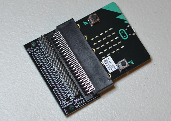
Figure 2-7: micro:bit inserted into edge connector breakout board
In the next chapter, I’ll introduce you to the several different ways of programming the micro:bit and delve deeper into the programming environment I prefer—MicroPython.