
Choosing a rendering appearance
Applying materials and shadows to objects
Editing and creating new materials
Walking through a model
Exporting and printing models and images
Creating a TourGuide slide show
Integrating SketchUp models with Google Earth
Exploring the 3D Warehouse
Finding additional resources
In the previous chapter, you saw how Google SketchUp can be used to create 3-D models. You learned how to create an object in 3-D space, and how to modify it and view it.
This chapter picks up where the last one leaves off. Now that your model is drawn, it’s time to add some realism. SketchUp offers a number of ways to configure the appearance of the object and its material, which is called rendering.
The surfaces of objects aren’t flat gray as the default material in SketchUp implies. Choose from hundreds of available textures and color them as you want. If that’s not enough, you can edit existing materials or create your own. Once a material is added to an object, transform it further to fit the object’s configuration. As a final realistic touch, see how to use shadows and simulate the time of day and year.
Once the models are finished, explore different ways to view the model. Take a walk through the model, or create different page views to bring it together as a TourGuide slide show. If your model is intended for use at a particular location, work with both SketchUp and Google Earth to build a model designed for a particular location on the planet. If your models aren’t enough to keep you going, explore models in the 3D Warehouse that you can download for inspiration.
One of the most interesting aspects of 3-D modeling is the art of applying textures and materials to surfaces of objects. With just a few tools, your model can appear quite realistic.
Before configuring the textures, look through the rendering settings to see how the objects in your model will be visualized.
Rendering refers to the process of converting the mathematical information in a drawing into an image of differing levels of quality and detail. Rendering can be defined by the way the faces of the model are treated, as well as how the edges are displayed.
To change the way the model is displayed, choose options from the View ![]() Rendering menu, the Rendering toolbar, or in the Display Settings dialog box, as shown in Figure 33.1. The Display Settings dialog box is a convenient way to set the appearance of your model, rather than using various toolbars and menu commands to set the mode. Also, having the settings collected in one dialog box lets you toggle different effects and settings on and off to see how they affect your model.
Rendering menu, the Rendering toolbar, or in the Display Settings dialog box, as shown in Figure 33.1. The Display Settings dialog box is a convenient way to set the appearance of your model, rather than using various toolbars and menu commands to set the mode. Also, having the settings collected in one dialog box lets you toggle different effects and settings on and off to see how they affect your model.
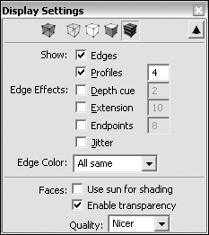
In the Display Settings dialog box, you can specify the following:
Rendering mode: Choose one of the modes from the buttons at the top of the dialog box. See the different modes later in this section.
Edge Effects: Choose an effect and modify its depth as you view the model. You can see the Edge effects later in the section.
Edge Color: Specify the colors for the edges of the model entities. The default is All same. Click the Edge Color down arrow and choose By material from the drop-down list to use an edge that is colored the same as your model’s objects. If you are working with a geometric model, choose By axis to color the edges red, blue, or green according to which axis an edge lies along.
Face rendering: You can select the Use sun for shading option to apply default sunlight, or select Enable transparency to use transparent materials, which is described in the Choosing Materials section. Finally, click the Quality down arrow and choose an option from the drop-down list for the display. You can choose Faster, Medium, or Nicer. The Faster display shows the least detail, but renders the quickest, while the Nicer display shows the most detail, but requires more rendering time. Medium shows some detail.
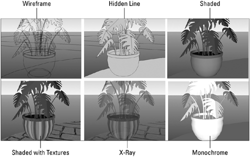
The model seen in Figure 33.2 shows the same potted plant using the available rendering modes. The modes are as follows:
Wireframe: This mode shows the model as its structural lines. You can’t see the faces, nor can you use tools such as the Push/Pull tool on a rendered model. Use Wireframe when you want to work with the simple structure of your models as it uses the least time to render the model’s image on-screen.
Hidden Line: This mode shows the model’s edges and faces, and is another way to work with the structure of the model without taking rendering time. Hidden Line mode is also good for printing a sketch of your model.
Shaded: This mode shows faces in the model reflecting a light source. You see the color applied to the faces in response to the light. If your model doesn’t have color applied, the default colors are displayed.
Shaded With Textures: This mode shows both the applied color and an applied texture as they appear reflecting the light source.
X-Ray: This mode can be used in conjunction with other modes. Applying the X-Ray mode adds a global transparency to the model, showing all faces. You don’t see shadow cast by model faces in X-Ray mode.
Monochrome: This mode is available from the View
 Rendering menu. Using Monochrome mode displays the model in the default program color and shows default shading.
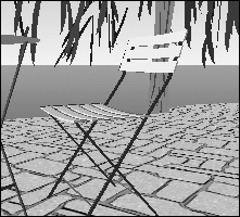
The Edge effects can add an edgy effect to your drawing, so to speak, making it appear sketch-like or look like a technical drawing, rather than simply rendered, such as the image shown in Figure 33.3. Choose the different effects from the Display Settings dialog box, or from the View ![]() Rendering menu.
Rendering menu.
To apply any of the edges, follow these steps:
Select the check box to specify whether to show Edges, Profiles, or both.
Specify a depth for Profiles or leave the default value. All values are shown in pixels.
Click to select the Edge Effect you want to use, and specify a depth in pixels as necessary.
Toggle different options on and off to view the effects in combination.
The different edge displays are shown in Figure 33.4. They are applied using the sun for shading, and rendered at the Nicer quality setting. All effects use the default pixel values, with the exception of the Extension effect, which uses 10 pixels to show in the figure.
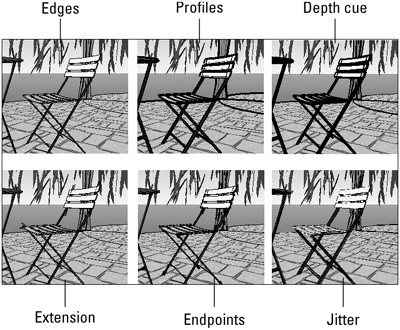
The edge options you can apply to your drawing include:
Edges: If you intend to use any edge effects, you must select the Edges check box. Edges follow the lines used in the model and are evenly applied throughout the model. In the figure, you see the edges of the chair and the tree are identified with a simple line.
Profiles: The Profiles option produces a heavier line that emphasizes the outlines of the major objects in the model. In the figure, for example, the Profiles show the detail at the right edge of the chair’s back.
Depth cue: Simulate the appearance of perspective using the Depth cue effect, with a heavier line closest to you and thinner lines farther away. The depth cue value specifies the size of the area closest to you in the model. In the example, the lines on the chair are heavier than those used on the tree or patio edges.
Extension: The Extension effect extends the lines past their endpoints, creating a technical sketch appearance, such as at the edges of the boards making up the chair’s seat and back. The length specified for the effect is the distance of the extension.
Endpoints: Instead of creating a sketched effect, use the Endpoints effect to highlight the tips of the edges. The area where two edges intersect appear as heavier lines, such as the ends of the chair’s legs, based on the value entered for the effect in pixels.
Jitter: The Jitter effect produces a pencil sketch appearance. Sketching by hand uses multiple lines that are often offset slightly. Jitter is either added or it isn’t—you don’t specify a depth.
Real life has color and texture, and so too can your models in SketchUp. Use the Paint Bucket tool to apply the color and texture, select paint materials from the Material Browser, and create your own material in the Material Editor.
Caution
In order to see the materials applied to a model, you must be using the Shaded or Shaded With Textures rendering options, described in the section “Applying a rendering mode” earlier in the chapter.
SketchUp offers many default library files containing materials ranging from tile to roof shingles to grass. There are many different rules, keystroke combinations, and processes to consider when applying color to your model. Please refer to the SketchUp help files or online resources for more information.
Follow these steps to apply a material or color to an object:
Click the Paint Bucket tool from the Getting Started toolbar, the Principal toolbar, or choose Tools
Paint Bucket; you can also choose Window Material Browser. The Materials dialog box appears, and shows the last color or texture applied.Click the Library tab on the Materials dialog box and choose an option. You can also click the directional arrows to the right of the Library drop-down arrow to flip through the library choices. The selected material appears in the swatch at the upper left of the dialog box, as shown in Figure 33.5.
Move the tool over the model and click to paint the faces of the object with color.
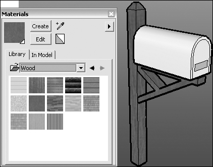
Instead of using one of the materials in the existing libraries, create your own. In this example, see how to change the default cherry wood material used to fill the mailbox post to a new wood color and texture.
Follow these steps to create a new material from an existing material:
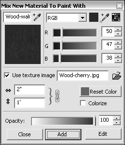
Click Create at the top of the Materials dialog box to open the Mix New Material To Paint With dialog box, as shown in Figure 33.6.
Specify the starting material in the upper-left swatch of the dialog and change if necessary. The original material shown is the cherry wood material.
Click the eyedropper, and move it over the model to sample a texture from the model if you want.
Click the text field at the upper left of the dialog box, and type a name for the new material if you plan to add it to the library.
A new material is named according to the existing material; the example is named <Woodcherry>1 by default. The new example material is named Wood-walnut.
Select or create the color for the new material at the upper right of the dialog box. The example uses a rich dark brown. Choose from several different methods to derive the color, including:
Choose a color model from the drop-down list; in the example RGB color is used. Click and drag the sliders, or type values in the RGB fields to define the color.
You can also click the eyedropper to sample an existing color on the model.
Click the Match Color button at the upper right of the dialog box to open the library to locate and select a color from an existing material.
Specify the texture map and its characteristics. The Use texture image option already is selected in the example as it starts from an existing texture, which is named in the field. Choose other options for the texture image including:
Click the Folder button to open the Choose Image dialog box. Locate and select the image to use for the texture on your hard drive. Click Open to insert the file into the new material and close the Choose Image dialog box.
Click the Lock/Unlock Aspect Ratio button to allow different values for the width and height as in the example.
Type measurements in the horizontal and vertical aspect ratio fields to change the measurements for the repeat of the texture’s pattern.
Click Reset Color to revert to the original color used by the material on which you are basing the custom material.
Select the Colorize option to force all colors to use the same Hue if there are discrepancies in the color, which doesn’t apply in the example.
Define the opacity for the material. The default is 100 percent, meaning there is no transparency in the object, and is the value used for the new material. Click the color bar to specify an opacity level, or type a value in the field.
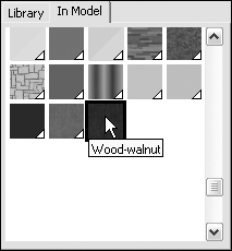
Click Add and then Close to close the Mix New Material To Paint With dialog box. In the Materials dialog box, the new material is added to the In Model tab’s thumbnails, as shown in Figure 33.7.
Right-click/Control-click the color swatch to display a shortcut menu and choose Add to Library. The new material, Wood-walnut, is included in the Wood library folder.
Continue working with the Materials dialog box, or close it. When you perform another operation, a dialog box appears stating there are changes made to the default library, and do you want to save them. Click Yes.
Note
You can pare down the number of swatches showing in the Materials dialog box on the In Model tab. Click the arrow at the upper right of the dialog box (shown in Figure 33.5) and choose Purge Unused. Anything you may have experimented with but decided against using is removed from the thumbnails list.
You don’t have to start from scratch, nor do you have to save anything that you have customized. If you find an appropriate material in one of the default Library files and apply it to your model, you can make changes to update its appearance automatically.
Follow these steps to edit an existing material:
Choose Window
Materials Browser to open the Materials dialog box.Click In Model to display thumbnails of the materials currently applied to your model.
Select the thumbnail of the material you want to modify, and click Edit to open the Edit Material dialog box.
Make the changes as desired. The dialog box is identical to the one shown in Figure 33.6 and discussed in the previous set of steps.
Click Close to return to the Materials dialog box, and close the Edit Material dialog box. Reapply the edited material to your model.
Rather than using the default program colors, you can change them in a model to suit your tastes. For example, the figures showing the garden model use a grass color as the default for the ground, rather than the default gray-beige color.
To change the default colors for your model, follow these steps:
Choose Window
Model Info to open the Model Info dialog box. Choose Colors from the column at the left of the dialog box to display the options.Select the Background options to use as the defaults. You can choose Sky, Ground, and to Show ground from below. Drag the slider to adjust the transparency of the ground if you want.
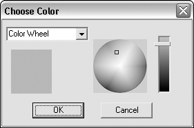
Click the color swatch for any color you want to change in the program, either for the geometry or for the background. The Choose Color dialog box appears, as shown in Figure 33.8.
Click the upper-left down arrow, and choose a color model from the drop-down list. The default is Color Wheel.
Click a location on the Color Wheel (or other model if chosen) to specify a color.
Drag the slider at the right of the dialog box to select a lighter or darker version of the color. The selected saturation is seen in the swatch at the left in the dialog box.
Make other changes as desired and click OK to close the dialog box and set the color.
Note
Depending on what you are building, the default colors for the background and sky may not be detailed enough. For example, a model of a house may be enhanced by showing it in its location or using actual views outside windows that you could see during a walkthrough. Use a vertical plane such as a rectangle, and apply a photo of the location on the face.
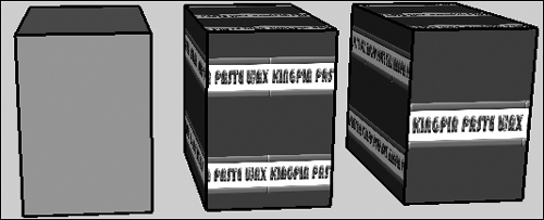
You aren’t restricted to using an object at the configured size. If you are applying a material to anything having a flat face, like a cube, you can adjust the appearance of the material on the face.
An example is shown in Figure 33.9. In the figure, the left cube is colored with a solid color. The center cube has a texture applied, which is intended to be used as a label for the object. There are two copies of the image tiled on the front face, as well as the left and top faces. Look at the right figure—the label on the front of the box shows a single label. The material wasn’t changed in its settings; instead, it was changed on the object itself.
Decide how and why you need to change a texture. If you want the object changed uniformly, change its dimensions in the Edit Material dialog box. If you decide you want to change it on one face, as in the example, follow these steps to make the changes:
Apply the material using a texture image as described in earlier steps.
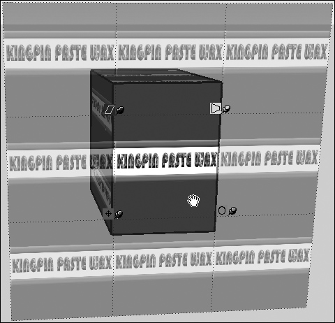
Right-click/Control-click the object and choose Texture
Position to open a positioning screen overlaying the image, as shown in Figure 33.10.Click and drag using the appropriate corner tool to reconfigure the object. Click the pin and move it in any direction to readjust the point at which the effect is applied; click again to anchor the pin to the grid.
From the upper right, the tools in clockwork order are:
Distort: Click the tool and then drag in any direction to change the configuration of the surface.
Scale/Rotate: Click the tool and then drag inward or outward to the center of the object to change the scale; drag up or down to rotate the texture.
Move: Click the tool and drag to move the texture horizontally or vertically.
Scale/Shear: Click the tool and drag inward or outward to the center of the object to change the scale, drag diagonally or vertically to change the angle of the geometry.
Click off the grid area to close the tool.
The final feature in applying a realistic appearance to your models is using shadows. The shadows can be cast based on the time of day and year. Shadows don’t have to be applied and reapplied when you make changes. Fortunately, the shadows update themselves automatically when you change the structure of the model or adjust the camera’s view.
The two types of shadows you can apply in the program are ground and face shadows. Shadows are configured for the entire model, not for a selected object.
Ground shadows are based on a flattened set of the model’s faces and placed on the background based on the angle of the sun. Figure 33.11 shows the impact of applying shadow to a model’s appearance. In the figure, the upper image shows the model without a shadow; the center image shows the model using a ground shadow.
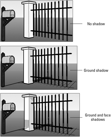
In three-dimensional space, objects cast shadows on other objects, as well as on the ground. Use the Face shadows in SketchUp to add more realism to your project. Again, like the ground shadow, the angles are based on the location of the sun. The same model using both ground and face shadows is shown at the bottom of Figure 33.11
If you want to configure the shadow settings, choose Window ![]() Shadow Settings to open the Shadow Settings dialog box.
Shadow Settings to open the Shadow Settings dialog box.
Tip
If you don’t want to make any changes to the shadow, choose View ![]() Shadows to apply the existing shadow settings.
Shadows to apply the existing shadow settings.
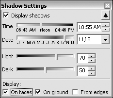
You can make these selections in the Shadow Settings dialog box, as shown in Figure 33.12:
Select Display shadows to show or hide shadow in the model.
Specify a time and date.
Drag the Light and Dark sliders to specify how much intensity is used in the shadow.
Select the shadows to display. Select On faces, On ground, or From edges; faces and ground shadows are realistic in appearance, the From edges shadow casts shadow only from the lines that make up the margins objects.
After working hard to learn the program and build a model, be sure to take advantage of the demonstration and presentation options SketchUp offers. You can set different views and then save the appearance as a page, which can be used for an animated tour of your model.
Here are some different presentation methods to consider:
Add information such as dimensions and labels, which is described in the section “Understanding entities.”
Show the interior of an object using a section cut effect, which is described in the sidebar “Showing a Cross-Section.”
Create a walkthrough showing the details of your model from varying perspectives at eye level.
Design a TourGuide tour that shows an animated tour of the model.
Print the model.
Export the model as images.
Using the model with Google Earth.
A walkthrough is a process you design using some of the Camera tools. While it isn’t necessarily an export or demonstration option, it serves much the same purpose. That is, it shows you the contents of your model in some way. A walkthrough is intended to simulate walking through the model as if it were in the real world. To accomplish the proper perspective, SketchUp lets you adjust your point of view to use a specific height and angle to the model.
Use the Walkthrough toolbar as a convenient way to define your view. Choose View ![]() Toolbars
Toolbars ![]() Walkthrough to open the toolbar. There are three tools, including:
Walkthrough to open the toolbar. There are three tools, including:
| |
| |
|
To create a walkthrough, follow these steps:
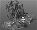
Click the Position Camera tool and click a point on your model. In Figure 33.13 the tool is placed on the patio close to the water feature at the default height of 5 feet, 6 inches.
To change the level of the point of view, type a different height in the VCB. The camera zooms into the specified location, and the tool changes to the Look Around tool automatically.
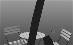
Click and drag the Look Around tool to rotate the view around you. In Figure 33.14, the view shows the table and chairs on the patio through the tree branches from a location just in front of the water fountain.
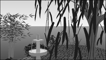
When you are ready to move on, click the Walk tool and click a location where you Want to travel next. Drag the tool to walk through the model. In Figure 33.15, the walk has returned to the patio fountain.
You can produce a TourGuide tour that works much like a slide show presentation in SketchUp. The tour is made up of different pages of your model showing different perspectives, details, section cuts, and so on.
Follow these steps to produce a TourGuide tour:
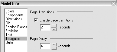
Choose View
TourGuide Settings to open the Model Info dialog box displaying the TourGuide tab, as shown in Figure 33.16. Click Enable page transitions to include a transition between slides. Click the up or down arrows to change the time in seconds.Type a value for the Page Delay or click the up or down arrows to change the time in seconds. Close the dialog box.
Choose Window
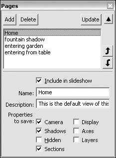
Pages to open the Pages dialog box, as shown in Figure 33.17. The model includes one default view called Home that is shown at the upper left of the model, below the toolbars.Move the view of the model to display what you want to see in a page. You can make any sorts of modifications such as changing shadow, rendering mode, time of day, and so on.
Type a name for the page in the Name field, and add some detail in the Description field if you want. The new page is added to the list at the top of the dialog box.
Select the Properties to save to include in the model’s page from the check boxes at the bottom of the dialog box.
Continue adding pages as desired. When you finish, check the sequence of the pages at the top of the Pages dialog box, and click the up or down arrows to move a selected page in the order.
Deselect the Include in slideshow check box for any slides you want to omit from the slide show.
Close the dialog box.
You can check through the pages you have defined from the program window. Each new page is tabbed at the top of the model’s view, as shown in Figure 33.18. Click a tab to display the view in the program window.
When you want to play your slide show, choose View ![]() TourGuide
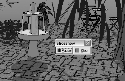
TourGuide ![]() Play Slideshow. The Slideshow controls open, as shown in Figure 33.19. Your slide show plays according to the settings you specify. Click Stop to stop the show.
Play Slideshow. The Slideshow controls open, as shown in Figure 33.19. Your slide show plays according to the settings you specify. Click Stop to stop the show.
The free version of SketchUp includes a number of different export options. One is the ability to export shots of the model in different image formats. Your model could become a cover for a CD containing drawings and other elements from the model, either prepared in SketchUp or exported from SketchUp and manipulated in other programs.
You can export many different views from your model as images in several formats. To export images from your model, follow these steps:
Position the model in the program window as you desire. The exported image includes only what is shown in the program window.
Choose File
Export 2D Graphics to open the Export 2D Graphics dialog box. The file uses the model’s name and the PNG image format as defaults.Name the image file as desired. Click the Export type down arrow and choose another image format from the drop-down list if you want. You can export as JPG, TIF, or BMP, as well as PNG.
Click Export to process the image and save it.
In the free version of SketchUp, you print your model as it exists. If you are using SketchUp Professional, you can specify Print to Scale and span across pages options to let you print a large drawing from a standard printer. You can also specify other settings such as the quality of the image output.
To print a model, follow these steps:
For added realism and the chance to tinker with another intriguing program, you can use material from both Google Earth and SketchUp to create and test models, and to upload a finished model to a specific location.
Cross-Ref
Refer to Chapter 13 for a discussion of Google Earth.
SketchUp conveniently includes the Google Toolbar that includes several commands for working with the two programs. The toolbar and its contents are listed in Table 33.1.
Table 33.1. Tools for Working with Google Earth
Looks Like | Name of Tool | Used For |
|---|---|---|
Get Current View | Download an image of the current view shown in Google Earth to use for placing a model | |
Toggle Terrain | Show alternate 2-D and 3-D versions of the current view for creating and placing your model | |
Place Model | Place a temporary version of your model on the current view in Google Earth | |
Get Models | Access the 3D Warehouse repository of models | |
Share Model | Upload a completed model to share via the 3D Warehouse |
To make the model work in an online location in Google Earth, you need to work with both programs. Before you start in SketchUp, open Google Earth and follow these steps to optimize settings for capturing a terrain image:
Choose Tools
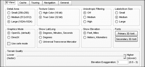
Options to open the Google Earth Options dialog box. The 3D View tab is shown by default, as seen in Figure 33.20.In the Detail Area, select the Large (1024 × 1024) radio button. You must have the largest detail area possible for a good terrain image.
In the Terrain Quality section, type a value of 1 in the Elevation Exaggeration field. Drag the Quality slider to the Higher end, depending on the speed of your Internet connection.
Click OK to close the dialog box and apply the settings to the map area in Google Earth.
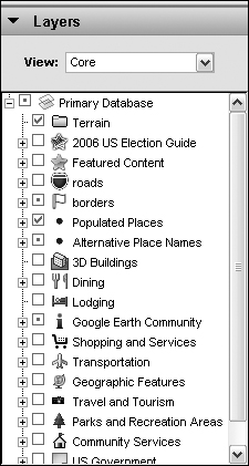
In the Layers sidebar, toggle the Terrain Layer to visible. If the sidebar is hidden, choose Tools
Sidebar to display it at the left of the program window, as shown in Figure 33.21. The terrain image for modeling in SketchUp uses a specific layer included with the terrain image, which is described in the next section.Using the Google Earth tools, display the location in the program window where you want your model to appear.
After the view is set in Google Earth, switch to SketchUp. Whether you close Google Earth depends on your modeling workflow and Internet connection.
Follow these steps to create your model using a Google Earth view as a terrain map:
Click Get Current View to get an image of the current view from Google Earth. This image contains the location information needed to properly place the model at the correct location in Google Earth.
Note
When you view your imported map image in SketchUp, if the map image appears solid black, change one of the graphics mode options. In Google Earth, choose Tools
Options to open the Google Earth Options dialog box, as shown in Figure 33.20. Select the Direct X option instead of Open GL in the Graphics Mode area of the dialog box. Close the dialog box, and restart Google Earth to change the graphics engine. Recapture the image.Create your model on top of the 2-D image, and move it to the appropriate location on the map, such as in the example in Figure 33.22.
Click the Toggle Terrain button on the Google Toolbar to toggle to the 3-D image. Reposition the model to conform to the terrain in the 3-D image if you are using terrain with a lot of elevation differences.
If the appearance of the map is distracting, select the map on the drawing and choose Windows
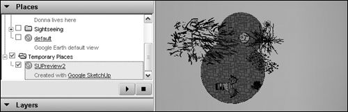
Material Browser to open the Materials dialog box. Click the In Model tab and select the map, which is added to the textures when imported into the model. Click Edit to open the Edit Material dialog box, and drag the Opacity slider left to decrease the map transparency. Click Close to exit the Edit Material dialog box and close the Materials dialog box.Click the Place Model button on the Google Toolbar to place the model in Google Earth. SketchUp creates a temporary file of your model and places the model in Google Earth at the proper location. As you can see in Figure 33.23, the model is listed in the Temporary Places in the Places list in the sidebar.
If you decide you don’t have enough models or want to look for inspiration, SketchUp offers the 3D Warehouse.
The 3D Warehouse is an online storage site containing hundreds of different models. Anyone may search and download models, but to submit your own, you need to log in using your Google Account.
On the Web
Find models of buildings, furniture, plants, and so on contributed by SketchUp users from around the world at http://sketchup.google.com/3dwarehouse/.
The 3D Warehouse models are freely available for you to share, use, and even display on your own Web site.
Follow these steps to locate and download a model:
In SketchUp, choose Google
Get Models or click the Get Models button on the Google toolbar to open the 3D Warehouse in a browser window.Find the model you want to work with. You can:
Scroll through the list on the opening page of the 3D Warehouse browser window and choose a category from either the Popular, Recent, or Google Picks sections.
Search for a model based on its name, description, location, type, or other term.
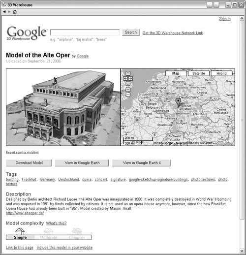
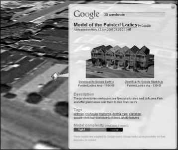
Select a model in the search returns displayed in the browser window to open a window with more information on the selected model, such as in the example shown in Figure 33.24.
The information includes a description, the keyword tags associated with the model, its location on a map, and a preview of the model.
Click Edit with Google SketchUp to open a dialog box asking if you want to load the model directly into your Google SketchUp model. Click Yes to load the model into the current model open in SketchUp; click No to save the model to your hard drive.
If you click No, locate and select the folder in which you want to save the model in the Save As dialog box, and click Save.
If you click Yes, the model is downloaded and placed. Depending on the conditions attached to the current model and the one you are downloading, you may have additional dialog boxes to specify where the model is placed:
If both the open model and the model being downloaded have specified locations on Google Earth, a message asks if you want to place the model yourself. Click No to have the model sited at its Google Earth location; click Yes to place the model on the program window.
If your model doesn’t have a location and the downloaded model has a location, it is placed on the ground plane centered at the origin point with green=north, red=west, and blue=up.
If the model is an object, such as a bumblebee or a teapot, the model is selected automatically on the ground plane and the Move tool is active.
The community surrounding SketchUp is growing as the program and its accompanying features grow. Here are a few sources of information and interaction for you to learn more:
http://earth.google.com/intl/en/3d.html: Download and install the 3D Warehouse Network link, a KMZ file used by Google Earth. After you download the file and open Google Earth, you see house-shaped markers indicating the locations of 3-D models, as shown in Figure 33.25.
http://sketchup.google.com/components.html: You don’t have to reinvent the wheel. Rather than starting a model from scratch, Google offers literally hundreds of components that can be added to your models. In addition to the libraries that are installed with the program, download libraries of objects ranging from Transportation to Architecture in both Windows and Mac OS X versions.
www.sketchup.com/training: Some people prefer to learn in a classroom situation. Visit this site to see a list of training courses available in your area.
http://download.sketchup.com/OnlineDoc/gsu_win/GoogleSketchUpHelp.htm: A standard type of Help file system, including Contents, Index, and a Search frame, is available from this site. The Help files include both SketchUp and SketchUp Pro 5.
http://sketchup.google.com/tutorials.html: If you want to see how something is constructed in SketchUp, visit this site for a list of videos. The set of seven SketchUp videos includes three quick-start videos, a video showing how to use the 3D Warehouse, and three videos on applying textures.
http://sketchup.google.com/examples.html: To inspire you as you make your way into the world of 3-D modeling, this site contains a number of georeferenced models for a number of famous buildings, such as the Eiffel Tower. You can also view a number of nongeoreferenced models.
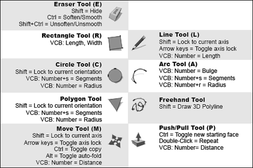
http://download.sketchup.com/GSU/pdfs/QuickReferenceCard.pdf: Be sure to download and print a copy of the reference sheet you access at this site. You can find a key to the toolbar icons, mouse buttons, and combinations using tools, some of which are shown in Figure 33.26. If you are working in SketchUp, choose Help
Quick Reference Card to open the document.http://groups.google.com/group/sketchup: Share your expertise and pick up pointers, advice, and troubleshoot problems at the Google SketchUp Help group. You must become a member of the group to post messages.
Cross-Ref
Read about Google Groups in Chapter 22.
This chapter carried on with a look at Google SketchUp. As you have seen, it is a substantial program, especially for free software!
In this chapter, you saw how to add realism to your model using different types of material that simulate anything from pansies to glass to rusty metal. In addition to using preconfigured materials, you saw how to edit materials from the libraries, how to create and add a new material, and how to adjust a material once it is placed on your model.
In the latter part of the chapter, you learned that SketchUp includes several ways to export content from a model, including printing pages and creating a TourGuide slide show. You saw how Google Earth and SketchUp work together to identify locations and to incorporate that data into a model for placing it on the map. Upload models to the SketchUp 3D Warehouse, where you can also find and download hundreds of different models to incorporate into your projects.
And now for something completely different: In the next chapter, dive into the world of online commerce and take a look at Google AdWords.