
Working in three dimensions
Drawing objects
Defining entities
Using the Instructor
Modifying an object’s geometry
Grouping objects and creating components
Setting the camera view
Pop quiz: What do you put on the Goggle Earth view of your street?
Answer: A 3-D model of your house, of course.
It may seem like a far-fetched idea, but you can do it using SketchUp. SketchUp is a full-featured program that allows you to create models of anything from teapots to tankers, sundials to skyscrapers. Google offers SketchUp in both a free version-used in this chapter-as well as a Professional version.
There are several integral stages to 3-D modeling that are covered very briefly in this whirlwind introduction to the program. You see how to draw a model, and how to manipulate and view it in this chapter. In the following chapter, read more about using 3-D models built in SketchUp.
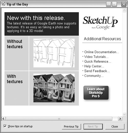
When you open SketchUp, a Tip of the Day dialog box appears like the example shown in Figure 32.1. Click Previous Tip or Next Tip to read the tips. From the Tip of the Day dialog box, click one of the links to access online resources and the SketchUp sites. Close the dialog box to get into the program itself.
Tip
If you prefer, deselect the Show tips on startup check box at the lower left of the dialog box. You can access the online resources through the Help menu in the program.
The SketchUp interface uses two windows, as shown in Figure 32.2. The program window is used to build and manage your models, and the Instructor is a secondary window that provides instruction and guidance for each tool that you select in the program. Both windows can be resized.
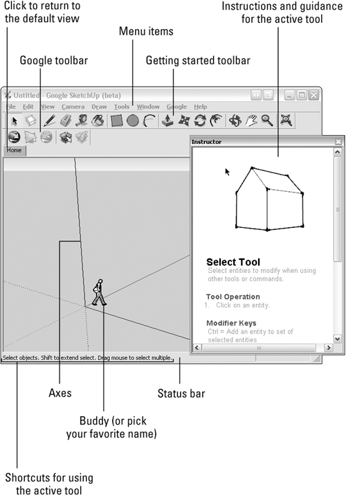
The Instructor window floats above the program window, regardless of which window is active. To collapse the Instructor window, click anywhere on the upper bar of the window. If you click the Close button at the upper right of the Instructor window, choose Window ![]() Instructor to reopen it.
Instructor to reopen it.
The default organization of the SketchUp window is shown in Figure 32.2. The program includes several main menu items, described briefly in Table 32.1.
Table 32.1. Menu Groups in SketchUp
Heading | Contains |
|---|---|
File | Open, Save, Import/Export, and Print commands are located in the File menu. |
Edit | In addition to the usual types of Edit commands, such as Cut/Copy/Paste, find specific types of editing, such as Make Component and Make Group. |
View | Find the toolbars in the View menu, as well as a number of different ways to view the model. |
Camera | Specify how the model is viewed based on different perspectives, zooms, and camera positions. |
Draw | Find commands for drawing basic elements such as rectangles, polygons, and lines in the Draw menu. |
Tools | Find tools, including many found on the Getting Started toolbar, in the Tools menu. |
Window | Open information dialog boxes, browse and edit materials, open the Instructor dialog box, and the preferences using commands in the Window menu. |
Find commands for viewing and getting models online. | |
Help | Find commands to open SketchUp and Ruby help, as well as a number of online sources. Reopen the Tip of the Day dialog box, and view the Quick Reference card. |
Two toolbars are displayed in SketchUp when you open the program, including the Getting Started and Google toolbars. The Getting Started toolbar combines tools from a number of toolbars to give you the basic tools needed to start and edit a drawing. The Google Toolbar offers several commands for accessing and downloading online information. The contents of the Getting Started toolbar are listed in Table 32.2.
Table 32.2. Tools on the Getting Started Toolbar
Name of Tool | Purpose | |
|---|---|---|
Select | Use for selecting one or more objects that are then modified by other tools or commands | |
Make Component | Combines two or more objects into a single unit that is a named, separate object | |
Line | Use to draw lines or edges of objects | |
Eraser | Use to erase objects one at a time | |
Tape Measure | Use for measuring distance, scaling a model, or creating construction guidelines for placing objects | |
Paint Bucket | Use for creating and selecting materials and colors, and then applying them to entities | |
Rectangle | Use to draw a rectangular Face entity | |
Circle | Use to draw a circular Face entity | |
Arc | Use to draw an Arc entity | |
Push/Pull | Use to either add or remove volume from a model by pushing or pulling Face entities | |
Move | Use to move, copy, or stretch entities | |
Rotate | Use to rotate, stretch, distort, or copy entities along a curved path | |
Offset | Use to create copies of lines that are at a uniform distance from the original lines | |
Orbit | Use to rotate the camera around the model | |
Pan | Use to move the camera view vertically or horizontally | |
Zoom | Use to move the camera view inward toward you, or outward away from you | |
Zoom Extents | Use to fill the view to a distance where the entity is centered in the drawing window at a magnification that shows the entire content |
You are familiar with working in two axes on a computer screen. To represent a third dimension, another axis simulates an object moving toward you or away from you-coming out of the ground or moving underground is another way to describe the movement.
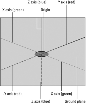
SketchUp uses a standard 3-D coordinate system of three axes called X, Y, and Z, as shown in Figure 32.3. Keep these ideas in mind as you learn to move around in 3-D space in SketchUp:
Each axis can have both negative and positive values. In the program, the positive directions are shown as solid lines, while the negative directions are shown as dotted lines.
Each axis uses a different color. Although you can’t see different colors in the figure, in the program the X axis is green, the Y axis is red, and the Z axis is blue.
The point at which all three axes intersect is called the origin.
The ground plane refers to the plane at which the X axis (green) and Y axis (red) lines run.
The simplest object you work with in SketchUp is a line, or edge. Lines are combined to form faces. Models are composed of edges, faces, and other objects or entities. The entities available for building a SketchUp model include:
Line: A line, or edge, is straight and forms the connection between two points.
Face: Faces are created automatically when three or more lines or edges on the same plane form a closed shape. Faces have a front side and a back side. SketchUp puts the front side of all faces on the outside of models.
Arc: An arc entity is a combination of several line segments connected to form the curvature of the arc. The combined lines act as a single entity. An arc is drawn with the Arc tool.
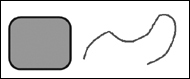
Curve: A curve entity is drawn with the Freehand tool. It is made up of several line segments connected together that act as a single line. A curve may be closed, meaning it begins and ends at the same point, or open, beginning and ending at different points like the examples shown in Figure 32.4. Both open and closed curves have lines, but only the closed curve has a face as well.
Polygon: Use the Polygon tool to draw a polygon entity. Polygons are made up of a radius and three or more sides.
Rectangle, Circle: These entities are composed of several lines or edges using specific geometric relationships.
3D polyline: A 3-D polyline entity is like a curve in that it is made up of a number of lines that act as one but doesn’t affect a model’s geometry. A tracing of an imported drawing or hatched lines used to decorate a model are examples of a 3-D polyline.
Group: Group entities are two or more entities of different types that are combined to make it simpler to perform operations like copying or moving.
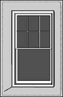
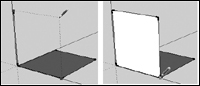
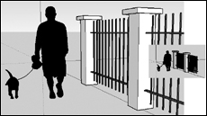
Component: Component entities are like groups in that they can be created from two or more entities of different types. A component is a named entity that you can reuse in any model, such as the window shown in Figure 32.5.
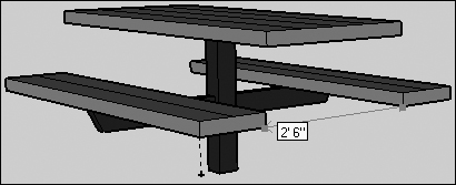
Construction line and Construction point. Use a Construction line or point entity as a drawing guide, such as the distance between the benches shown in Figure 32.6. Unlike other entities, a construction line or point is temporary, and can be hidden or erased. Construction lines and points are drawn with the Tape Measure tool. Choose Edit
 Construction Geometry and choose Hide, Unhide, and Erase to manipulate the construction lines or points in a drawing.
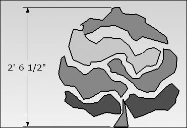
Dimension: A dimension entity is a notation on a model that indicates the length or radius of an edge, such as the height of the shrub shown in Figure 32.7. The values shown move and update automatically as you make changes. Add Dimension entities to a model using the Dimension tool.
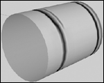
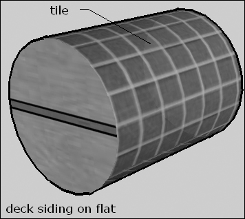
Surface: A curved surface, like the roundness of a cylinder, is made up of a number of faces. The higher the number of faces, the greater the appearance of a smooth, curved surface. The faces combined to create the smooth appearance are surface entities (see Figure 32.8).
Image: An Image entity is a type of group made up of a face with an applied bitmap. An Image entity can be manipulated, such as scaled or rotated, but not made nonrectangular. Add an image by choosing File
Import 2D Graphic, and selecting the image.Text: Text entities are used to add annotations to a model. Text can be used as Leader Text, which has leader lines and is attached to a face, like the upper label in Figure 32.9, or Screen Text, which remains fixed at a specific location, like the lower label in Figure 32.9.
Take the time to understand how the coordinate system works in SketchUp. An internal program feature called the inference engine uses the program’s coordinates to help you draw accurately by identifying probable points you will add to the object. Nearly all objects can be created in SketchUp using the Line tool and the program’s inference engine.
A drawing in SketchUp starts out as a 2-D object built by drawing and joining lines. SketchUp assists you to make the lines that create the 3-D object.
Follow these steps to draw a simple cube:
Click Home on the upper left of the drawing area to orient the screen showing the origin of the three axes in the center.
The Home tab defines a page view for the model, and is a default page. Additional pages can be added to the model to produce a TourGuide slide show
Cross-Ref
Read about creating a slide show in Chapter 33.
Click the Line tool on the Getting Started toolbar. Click and drag along one axis as shown in Figure 32.10. Release the mouse to finish the line segment.
Move the tool upward, perpendicular to the Y axis green line and click and drag to add the second edge. Drag left parallel to the X axis red line to add the third edge, shown in the center image in Figure 32.10.
Draw the fourth edge along the Y axis green line to complete the shape at the start point. Double-click the mouse to complete the shape. The closed shape is automatically filled, indicating it has a face, shown in the right image in Figure 32.10.
Draw up or down in the direction of the Z axis blue line to start drawing in 3-D space. Click to place the endpoint and finish the line, shown in the left image in Figure 32.11.
Draw the next point, watching for the prompts as you move the Line tool. Drag to close the side, and add the second face, such as the example shown at the right in Figure 32.11.
Choose View
X-ray to make the faces added to the drawing semitransparent, as shown in Figure 32.12. You can also rotate the image or start drawing from the back toward the front.Continue adding lines and closing faces of the object. The final 3-D cube is shown in Figure 32.12.
You don’t have to guess or estimate the size of an element as you draw. Instead, use the value control box (VCB) at the bottom right of the program window on the status bar. The VCB displays dimensional information as you draw.
There are different ways to use the VCB depending on your preferred way to work. Follow these steps to use precise values for drawing:
Click the Drawing or Modification tool you want to use from the toolbars or menus. When the tool is selected, the VCB displays a cursor for typing.
Choose a method for drawing and assigning the value:
Use the Drawing or Modification tool and then type the value in the VCB.
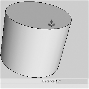
Type the value in the VCB, such as 10” shown in Figure 32.13, and then drag the Drawing or Modification tool on the drawing.
Press Enter/Return to commit the value to the drawing.
Repeat typing the value and committing it to the drawing as necessary.
After you finish with the tool and select another tool in SketchUp, you can’t return to the VCB to redefine the object’s measurement. Whether the program is using the measurements you specify or not, the program converts the value to its default system. For example, typing a value in centimeters is changed to feet and inches automatically if you use the default program system.
Note
The default unit of measure for your models is the Architectural format. To change to a different format, such as Decimal or Engineering, choose Window ![]() Model Info, and click the Units heading to display the settings. Choose the format, precision, and characteristics for angles in the dialog box.
Model Info, and click the Units heading to display the settings. Choose the format, precision, and characteristics for angles in the dialog box.
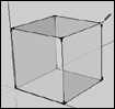
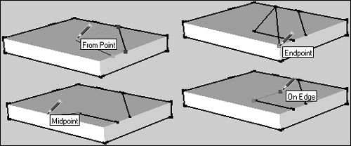
Instead of drawing lines and connecting points yourself, let the SketchUp inference engine feature assist you in drawing accurately. As you draw lines, the inference engine infers points from other points in your model. For example, if you draw a cube, the program reads where your cursor is currently located, determines what points are in the area, and shows you the options as you draw.
You see the points that are identified as different color indicators and pop-up tooltips. Carefully watch for the changes in the color of lines and points on the model and read the tooltips to build your model. Figure 32.14 shows several examples of how the inference engine suggests drawing cues.
Whether you have modeled a cube or a spaceship, SketchUp defines anything you draw as geometry. There are a number of 3-D drawing techniques that can be applied to the geometry using tools in SketchUp. Most of the tools are based on the fact that you can add more faces and edges to existing geometry and then make changes based on those additions.
One SketchUp feature that makes modeling objects simple to do is the ability to divide an object’s structure, and then remove the dividing lines and restore the original if desired. The only tool required is the Line tool. SketchUp refers to the addition of extra edges and faces as dividing.
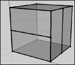
A complete cube drawn in SketchUp is shown in Figure 32.14. To add additional lines and faces, follow these steps:
Click the Line tool on the Getting Started toolbar.
Drag from an edge along one of the cube’s faces across the face. The inference engine shows you probable points, such as the midpoint.
Release the mouse when you place the line as desired. Continue adding other lines as desired.
Check the model shown in Figure 32.15. The front is split horizontally, and the face to the right is split vertically.
To remove a dividing edge, click the Select tool on the Getting Started toolbar and then click the edge to select it, such as the vertical line shown in Figure 32.16. Press Delete to remove the line and heal the face of the cube.
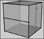
Using the Line tool to add extra edges divides only the faces on a cube, but doesn’t cut through the cube to make separate objects.
Extrusion is a method of changing the geometry of an object by increasing or decreasing the dimensions in one plane or axis. The previous section that explains how to add lines to make a square into a cube is one example of an extrusion.
The Push/Pull tool on the Getting Started toolbar is an extrusion tool. Starting from a simple shape such as a 2-D square or circle, you can easily push or pull the shape into a 3-D cube or cylinder, like the examples show in Figure 32.17.
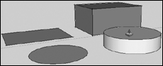
Using the Push/Pull tool isn’t restricted to a simple shape.
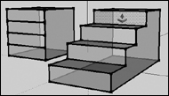
To use the Push/Pull tool to convert a shape from a simple cube to a more complex staircase object, follow these steps:
Click the Push/Pull tool on the Getting Started toolbar, and click one of the faces on the cube. The selected face shows an overlay of dots indicating it is active.
Drag to increase the size of a section of the cube.
Repeat the selecting and dragging of the cube’s faces.
Make adjustments as necessary by clicking an extruded face with the Push/Pull tool and dragging. The finished staircase is shown at the right of Figure 32.18. Where the original cube shown at the left of the figure has four faces specified, on the plane there are now four steps in the staircase.
You can modify the geometry of an object by manipulating a face or edge, as shown in the previous examples using the Push/Pull tool. The SketchUp geometry is called sticky geometry, as moving an edge or face causes the objects attached to the edge or face to move as well.
Other tools can be used for modifying faces and edges on an object, and can be applied individually or in a sequence. Here’s an example using a variety of tools in sequence to create a finished model of a birdbath, complete with a base, column, and basin.
The object begins with a simple rectangle, and then the Push/Pull and Offset tools are used to build the beginning of the structure.
Click the Rectangle tool and draw the starting square.
Use the Select tool to select the entire rectangle.
Use the Push/Pull tool to drag upward, completing the base of the object. In the example, the base is 4 feet square and 5 inches thick.
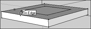
Click the Offset tool and drag it over the surface of the cube. As you drag, a rectangle is drawn using the same proportions as the original and centered over the original. Drag up/down and in/out to resize the new rectangle, as shown in the example in Figure 32.19.
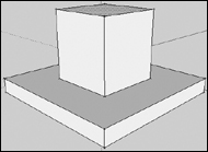
Click the Push/Pull tool, and move it over the new rectangle. When you see the dotted lines that indicate the new rectangle is selected, drag upward to add a box shape on top of the original, as seen in Figure 32.20.
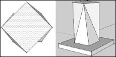
The next stage is to rotate the top of the rectangle to create a twisted, multisided effect for the top box. Although the tools can be used regardless of the view you show in the program window, it’s simpler to organize what you see to make the tools easier to understand and to use.
The example model is drawn using the default SketchUp positioning. To view the object from the top down, choose Camera ![]() Standard
Standard ![]() Top. The modified view shows the tops of the concentric boxes.
Top. The modified view shows the tops of the concentric boxes.
Note
Depending on how you place the object initially, using the Top view may or may not show you the object directly.
To rotate the top box numerically, follow these steps:
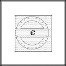
Click the Rotate tool on the Getting Started toolbar, and move it over the objects on the screen. The tool displays a protractor, shown in Figure 32.21.
Move the tool over the center of the upper box, viewed as the smaller square in the model when seen from the top. Click and drag with the tool to identify the object to which the tool is applied.
Type an angle for the rotation in the VCB and press Enter/Return. The example is rotated 345 degrees. The top view now shows some shallow triangle shapes on each side of the inner rectangle, as seen in the left image in Figure 32.22.
Reset the view to the default by clicking Home on the upper left of the program window below the toolbars. The sides of the upper box are now angled, resulting from rotating the top surface. Read the sidebar “Folding the Model” for more information.
Even though the vertical faces of the column of the birdbath are now pairs of triangles, the top face is still a flat rectangle, and the rest of the model is built from the top face.
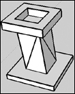
The finished birdbath model is shown in Figure 32.23.
The final steps to complete the basic model include:
Selecting the upper face of the top shape.
Using the Offset tool to draw a square centered over the top shape and larger than the twisted column.
Using the Rotate tool to reverse the rotation for the new square. The square is placed over the twisted column, but is not in alignment with the base. Setting the Rotation value to -345 degrees makes the new square drawn with the Offset tool match the orientation of the original base of the object.
Using the Push/Pull tool to pull up the sides of the birdbath’s basin, leaving the basin space the size of the column.
If you want the basin of the birdbath to be larger or smaller than the column’s dimensions, use the Offset tool to add one more square between the column and the square that defines the birdbath’s margins.
SketchUp helps you build complex geometry using a set of four processes that include:
Intersecting two forms
Defining new edges where the objects intersect
Redefining the geometry
Deleting extra lines and faces from the combined geometry
The birdbath model can be developed into a postmodern sculptural object using more tools and program commands.
Follow these steps to add some cutout details to the model:
Click the Rectangle tool on the Getting Started toolbar, and draw a rectangle on the screen. Click the Push/Pull tool, and extrude the rectangle to make a box.
Click the Select tool to drag a marquee around the box to select all its elements.
Click the Move tool on the Getting Started toolbar. The Move tool repositions an edge, face, or an entire object depending on the selection. In the example, the Move tool affects the entire box as it is entirely selected.
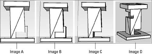
Drag the block from its drawing location on the screen to intersect with the column of the birdbath. Release the mouse once the block is positioned as shown in Image A in Figure 32.24.
The front face of the box is protruding through the face of the birdbath’s column. Notice that areas that intersect don’t display edges.
Choose Edit
Intersect with Model. The geometry of the block intersects with the geometry of the column of the birdbath. On the model, the areas of intersection now show edges, as seen in Image B in Figure 32.24.Click the Eraser tool on the Getting Started toolbar and click faces and edges in the intersected areas to remove them, as shown in Image C in Figure 32.24. New faces and edges are shown within the structure based on the intersected areas.
Add more cutouts to change the geometry as desired. In the final model, shown in Image D in Figure 32.24, another block has been used to cut out another area of the column.
Selecting the faces and edges of an object over and over can be tiresome and can lead to inaccuracy if you forget one edge or face. Instead of selecting the elements each time you need to work with them, create a group. If you want to have an object that can be reused, create a component instead.
To help you get organized, make groups within groups, components within groups, groups within components, and so on.
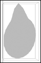
Groups are entities that hold other entities. For example, a polygon representing a flower petal is made up of one edge for each line used to draw the group and its face.
Follow these steps to create a group:
Click the Select tool on the Getting Started toolbar.
Drag a marquee around the content you want to include in the group.
Choose Edit
Make Group or choose Make Group from the shortcut menu. As shown in Figure 32.25, the group is shown with a bounding box identifying its components.
To ungroup a group and return it to its component elements you have to explode it. Select the group you want to explode with the Select tool. Then choose Edit ![]() Group
Group ![]() Explode, or choose Explode from the shortcut menu.
Explode, or choose Explode from the shortcut menu.
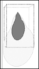
The contents in a grouped object can be edited within the context of the group. The flower petal shown in Figure 32.26 is composed of two groups. The smaller shape is nested within the larger shape. Double-click the group to open it in a group editing view. A group is open for editing when it is surrounded by a bounding box; other objects on the screen turn gray.
Make the edits as required, and choose Edit ![]() Close Group to exit the editing mode or choose Close Group from the shortcut menu.
Close Group to exit the editing mode or choose Close Group from the shortcut menu.
Applying Ruby Scripting
You can extend the functionality of the program and add components automatically using macros scripted with Ruby. Scripts can be downloaded from the SketchUp Ruby Forum online. Copy the script into the SketchUp Plugins folder in the SketchUp installation directory (Windows). For MacOS X, copy the script into the Macintosh HDLibraryApplication SupportGoogle SketchUpPlugins folder.
If you want to write your own scripts, choose Window ![]() Ruby Console to open a dialog box for writing Ruby commands and methods. Learn more about Ruby and find tutorials and help guides at www.ruby-doc.org.
Ruby Console to open a dialog box for writing Ruby commands and methods. Learn more about Ruby and find tutorials and help guides at www.ruby-doc.org.
If you design an object that you intend to use numerous times in your current project or think you will reuse in another project, build a Component object. Components are stored in the Component Browser. For some objects, such as a flower petal, the placement isn’t critical as you can and often do move the petals into a number of positions.
Caution
For some components, orientation is critical. For example, a door or window should be oriented to be parallel with structures such as walls and not cut through them.
To create a component, follow these steps:
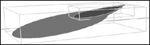
Click the Select tool on the Getting Started toolbar, and drag a selection marquee around the objects you want to include in the component. The two objects that make up a flower petal are shown selected with their respective grouped bounding boxes in Figure 32.27.
Click the Make Component button on the Getting Started toolbar, or choose Edit
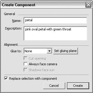
Make Component. The Create Component dialog box appears.Type information about the component as required, as shown in Figure 32.28. As a minimum, the component must have a name and may include other settings including:
Click the Glue to down arrow and choose an option from the drop-down list to define faces where the component can be placed. The choices include None, which is the default, as well as Any, Horizontal, Vertical, or Sloped.
If the component axis shown at the edge of the object isn’t oriented correctly, click Set gluing plane to activate a set of axes. Click the component where you want to set the origin for the component.
Click Create. The dialog box closes, and the multiple groups are replaced by a single component object.
Components are similar to groups in many ways, but very different in two important ways.
A component is created once and stored on your computer once. It doesn’t matter whether you use one flower petal or one hundred; the same amount of information is stored as a single component definition. Using instances requires fewer memory and processing resources than pasting copies of groups as the component definition is stored only once.
A copy of the component placed into a model is called an instance. Editing an instance makes the same edits to the component definition and changes all other instances of the component. In a group, on the other hand, each copy is an individual object unrelated to any others.
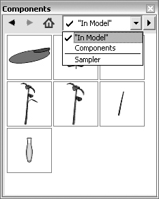
When it’s time to add an instance of the component into the model, choose Window ![]() Components to open the Components dialog box, your model library. Click the down arrow, and choose In Model from the drop-down list. The components used in the model you are working with are listed in the dialog box, as shown in Figure 32.29. Click the thumbnail for the component you want to insert and drag your mouse over the program window. You see a copy of the component; click to place the object where you want it located.
Components to open the Components dialog box, your model library. Click the down arrow, and choose In Model from the drop-down list. The components used in the model you are working with are listed in the dialog box, as shown in Figure 32.29. Click the thumbnail for the component you want to insert and drag your mouse over the program window. You see a copy of the component; click to place the object where you want it located.
Note
SketchUp offers a collection of components you can experiment with as you learn to use the program. In the Components dialog box, click the down arrow and choose Components from the drop-down list. The Sampler folder display appears in the dialog box. Double-click the Sampler folder to open it and display thumbnails in the Components dialog box.
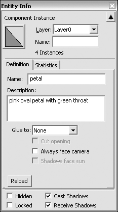
To check the component’s information and make changes, choose Window ![]() Entity Info to open the Entity Info dialog box, as shown in Figure 32.30. You see the default Layer0 defined at the top of the dialog box, as well as a label stating that four instances of the component have been used in the model. The Definition tab displays the information entered in the Create Component dialog box (refer to Figure 32.28). Click the Statistics tab to view a list of the component’s geometry, including edges, faces, groups, and so on.
Entity Info to open the Entity Info dialog box, as shown in Figure 32.30. You see the default Layer0 defined at the top of the dialog box, as well as a label stating that four instances of the component have been used in the model. The Definition tab displays the information entered in the Create Component dialog box (refer to Figure 32.28). Click the Statistics tab to view a list of the component’s geometry, including edges, faces, groups, and so on.
One of the most difficult concepts to grasp when working in 3-D is defining your point of view. SketchUp, like many 3-D modeling programs, uses a camera analogy to represent your view of the model.
By default, you look directly down at the ground from the sky, which isn’t a usual way of looking at things! However, the camera angles to the view of the ground because many SketchUp models begin on the ground, represented as the X and Y, or red and green axes, such as the example shown in the left of Figure 32.31.
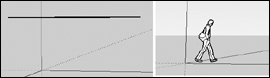
To produce the sense of modeling in three dimensions, you have to rotate the 3-D space to show the third dimension, which is visible in the right example in Figure 32.31.
To assist you in positioning and viewing your model, SketchUp offers two toolbars. The most common Camera tools are included on the Getting Started toolbar, as well as on the Camera toolbar. You can see the icons for the tools in Table 32.3.
Table 32.3. Using Standard Views
Looks Like | View Name | Shows | Example Location |
|---|---|---|---|
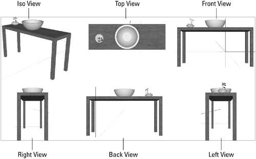
Iso | Shows a standard 3/4 view of the model | Upper left, Figure 32.33 | |
Top | Shows the top of the model | Upper middle, Figure 32.33 | |
Front | Shows the front of the model | Upper right, Figure 32.33 | |
Right | Shows the right side of the model | Lower left, Figure 32.33 | |
Back | Shows the back of the model | Lower middle, Figure 32.33 | |
Left | Shows the left side of the model Lower right, Figure 32.33 |
Cross-Ref
Read about another set of Camera tools used for creating a walkthrough in Chapter 33.
The tools you use regularly for placing the camera include the following:
Orbit tool: Click the Orbit tool from either the Getting Started or Camera toolbars, or choose Camera
Orbit. Move the cursor in any direction to rotate the camera around the center of the drawing.Pan tool: Click the Pan tool from either the Getting Started or Camera toolbars, or choose Camera
Pan. Click and drag the tool in any direction to pan the image, moving the camera either horizontally or vertically.Zoom tool: Click the Zoom tool from either the Getting Started or Camera toolbars, or choose Camera
Zoom. Click and drag the tool upward to zoom in, moving the camera closer to the model, such as the image in the left of Figure 32.32; click and drag the tool downward to zoom out, moving the camera away from the model, such as the image at the right in Figure 32.32.
Instead of using the tools and changing positions manually, you can use a set of standard views to check out your model. The icons for the views, their display characteristics, and the location of an image example are shown in Table 32.3.
Note
Content in a model can be shown in axonometric or perspective projections. An axonometric perspective shows a view of the model where lines appear parallel in both three-dimensional and two-dimensional space. Perspective projections show a distortion based on the vanishing point of the lines in the distance at the horizon. SketchUp uses a perspective view as its default.
This chapter introduced you to the 3-D world. Google SketchUp allows you to draw fairly sophisticated three-dimensional objects, buildings, and other entities. You saw how SketchUp defines three-dimensional space, and how to draw and specify measurements in that space.
The basis for modeling in SketchUp is a line and the inference engine, the feature in SketchUp that tracks the movement of your line and associates it with points, axes, and other objects in the area, helping you to draw more accurately and much more quickly than working on your own.
Once a shape is constructed, its geometry can be manipulated in many ways by using a variety of manipulation tools. For example, additional lines can be added to the face of an object and then extruded using the Push/Pull tool to form a complex structure. The geometry in SketchUp is said to be sticky, allowing the points, edges, and faces of an object to move along with anything that is being manipulated. Once perfected, objects can be combined into groups or stored as components for future use.
The Camera view in SketchUp can be adjusted in a number of ways, using standard views or working with tools that manipulate the view manually. Moving a camera around your model shows its structure, and points out the fact that a model would look much more realistic with some texture and shadow. Fortunately, all you have to do is turn the page. Up next, another chapter on SketchUp.