
Hardware Hacking
Introduction
The phrase “hardware hacking” can mean different things to different people. For some, hardware hacking may be related to telephone experimentation, lock picking, or setting up model railroad systems. In our case, hardware hacking is defined as modifying hardware appliances or electronic products to perform functions for which they were not originally intended. This could mean anything from a simple software replacement to a complicated electrical circuit attack.
Just about any piece of electronic equipment can serve as a candidate for hardware hacking. Particularly of interest to us are Personal Digital Assistants (PDAs), mobile telephones, and hardware authentication devices (such as dongles, token cards, biometric devices, and smart cards). Other common targets are any devices that are network-enabled and have embedded cryptographic functionality, such as routers, switches, virtual private networks (VPNs), and cryptographic accelerators.
This chapter focuses on hacking electronic hardware devices to gain a security advantage. This limits the discussion to security-related hardware devices that are designed to store sensitive information (such as cryptographic components or secret data) or that have some physical feature designed to make them harder to attack (such as epoxy encapsulation).
Hardware hacking requires a completely different cache of tools from the rest of this book: hardware hacking requires physical tools. This chapter covers the background and process of hardware hacking, tools and other resources that will aid in your endeavors, and a few real-world examples.
Understanding Hardware Hacking
Depending on your goals, what and how you choose to attack will vary. Generally, hardware hacking is done for the following reasons:
![]() General analysis of the product to determine common security weaknesses and attacks
General analysis of the product to determine common security weaknesses and attacks
![]() Access to the internal circuit without evidence of device tampering
Access to the internal circuit without evidence of device tampering
![]() Retrieval of any internal or secret data components
Retrieval of any internal or secret data components
![]() Cloning of the device (useful for authentication tokens and other identity-type devices)
Cloning of the device (useful for authentication tokens and other identity-type devices)
The process of hardware hacking is very different than network or software hacking, and can be broken down into two distinct phases: housing and mechanical attacks and electrical circuit attacks.
Housing and mechanical attacks examine the physical housing of the device. The goal is to understand the product manufacturing process and gain access to the internal circuitry. Things of interest here include tamper mechanisms, external interfaces to the outside world, electromagnetic and radio-frequency (EMI/RF) interference, and electrostatic discharge (ESD) susceptibility. We also want to examine any of the protocols being used to transmit data to devices external of the product (such as infrared, USB, Ethernet, wireless, or RS232).
Electrical circuit attacks examine the product circuitry and other internal components. The typical steps for this part include reverse-engineering the printed circuit board to create a schematic (an electronic road map) of the circuitry, and identifying and attempting possible attack vectors (such as physical memory access, timing attacks, IC delidding, and silicon die analysis). Most of the time, electrical attacks cannot take place until the housing/mechanical attacks are successful, since electrical attacks require access to the internal circuitry.
Opening the Device: Housing and Mechanical Attacks
The most common goal of mechanical analysis is to gain an overall understanding of the product and to access the product internals. Invasive physical access to the product circuitry is required to further the electrical circuit analysis. Tamper mechanisms are often designed into products to prevent or detect invasive attacks. Depending on the product, there might be no defense mechanism at all, or there may be multiple layers of protection.
The initial analysis of the product housing is to get a feel for the device’s manufacturing process. At this stage, it will become apparent how easy it is to open the device, and you will be able to detect if there are any tamper mechanisms in place.
Many product vendors (including those that make security-related products), do not take many steps to design secure enclosures for the protection of their internal circuitry and intellectual property. For example, opening some products is as simple as loosening a few screws or prying open the device with a hobby knife (as shown in Figure 14.1). At the other extreme, some highly secure cryptographic products (such as the IBM 4758 cryptographic coprocessor) that conform to the FIPS-140-1 or the newer FIPS-140-2 government requirements (http://csrc.nist.gov/publications/fips/fips140-2/fips1402.pdf) employ a number of tamper protection features in a layered fashion to prevent even the most detailed and advanced physical attacks.

At this initial product investigation stage, it is useful to obtain as much information as possible about the product. Publicly accessible databases, Web sites, and vendor press releases are a good start, and sometimes contain extremely helpful information as to how the product was designed and what security features (if any) are employed.
Examining the material properties of the product housing is useful, especially if the attack is taking place on a device that needs to be returned to the legitimate owner or the physical attack needs to go undetected. Of what type of material is the housing made? This can be any number of materials, including metal, plastic, or a composite. Each material has its own physical properties and plays a major role in determining how easy it is to penetrate the device: is the material brittle? Will it crack or break easily under stress? If the product housing consists of two pieces that are press-fit together, will the pieces break before the product opens? If the material is brittle, prying the housing apart might do more harm than good. Is the material soft? Many plastics are extremely susceptible to direct heat, which is often applied using a heat-gun to soften the glue that holds a two-piece design together. If the product melts or deforms easily, an attack using heat may be out of the question. If the material scratches easily, such as from a slip with a knife or screwdriver, how obvious is the damage to the naked eye?
It can also be useful to identify some of the product’s manufacturing processes. Understanding how the device was manufactured will give you some ideas on how to successfully open the device and whether or not you will need any special tools or equipment. How is the device put together? Is the product simply screwed together with a common-sized screw or hex heads, or does it require special tools to open? Is glue used to hold the housing together? If so, will the glue soften with under a heat-gun or is it a high-temperature glue that will remain sealed even when heat is applied? Is the housing a one-piece design? Many portable devices use sonic welding to “melt” a two-piece housing together and essentially create a solid outer shell. This makes it extremely difficult to open without noticeable damage to the casing.
Types of Tamper Mechanisms
There exist a large number of tamper mechanisms that can be designed into a product to protect or prevent access to components and data. Tamper mechanisms are divided into four areas:
Often, products have tamper mechanisms that can only be discovered by complete disassembly of the product. This may require obtaining more than one device in order to sacrifice one for the sole purpose of discovering any tamper mechanisms. For example, there might be a simple switch used to detect if the device is being opened, which would erase all memory contents as a result of the device’s being opened. Opening the device makes it apparent that the mechanism exists, but that particular device is rendered useless for further analysis. Once the mechanisms are noted, hypotheses can be formed about how to attack and bypass them.
Tamper Resistance
Tamper resistance mainly consists of a device’s packaging being designed to make tampering difficult. This can include such features as:
![]() Tight airflow channels (that is, tightly packing the components and circuit boards to increase the difficulty of optical probing using fiber optics)
Tight airflow channels (that is, tightly packing the components and circuit boards to increase the difficulty of optical probing using fiber optics)
A side benefit of well-implemented tamper resistant mechanisms is that they are often tamper evident, meaning that physical changes can be visually observed; it becomes obvious that the product has been tampered with. This presents the attacker with a more difficult challenge.
Tamper Evidence
Tamper evident mechanisms are a major deterrent for minimal risk takers (non-determined attackers). There are hundreds of tamper evident materials and devices available, mostly consisting of special seals and tapes to make it obvious that there has been physical tampering. However, most (if not all) of the available tamper evident mechanisms can be bypassed. In Johnston and Garcia’s Physical Security and Tamper-Indicating Devices paper (www.asis.org/midyear-97/Proceedings/johnston.html), the authors show how 94 different security seals (both passive and electronic), were defeated using rapid, inexpensive, low-tech methods.
Tamper evidence features are only successful if there is a process in place that requires somebody to check for tampering or if the legitimate user of the device notices a deformity such as a broken seal.
Tamper Detection
Tamper detection mechanisms enable the hardware device to be aware of tampering. Whether anything is done when tampering is detected by one of these mechanisms depends on the tamper response of the product (discussed in the following section):
![]() Micro switches, magnetic switches, and pressure contacts to detect the opening of a device or the movement of a particular component.
Micro switches, magnetic switches, and pressure contacts to detect the opening of a device or the movement of a particular component.
![]() Temperature and radiation sensors to detect environmental changes, heat and cold attacks, and X-rays (used for seeing what is inside of a sealed or encapsulated device) and ion beams (often used for advanced attacks to focus on specific electrical gates within an integrated circuit).
Temperature and radiation sensors to detect environmental changes, heat and cold attacks, and X-rays (used for seeing what is inside of a sealed or encapsulated device) and ion beams (often used for advanced attacks to focus on specific electrical gates within an integrated circuit).
![]() Flex circuitry and fiber optics wrapped around critical circuitry or specific components on the board. These materials are used to detect if there has been a puncture or break in the wrapper. For example, if the resistance of the flex circuitry changes or the light power traveling through the optical cable decreases, one can assume there has been physical tampering.
Flex circuitry and fiber optics wrapped around critical circuitry or specific components on the board. These materials are used to detect if there has been a puncture or break in the wrapper. For example, if the resistance of the flex circuitry changes or the light power traveling through the optical cable decreases, one can assume there has been physical tampering.
Tamper Response
Tamper response mechanisms are the resultant actions of the tamper detection mechanisms. Most often, the response consists of erasing critical portions of memory to prevent an attacker from accessing secret data. Response mechanisms may also do nothing but log the type of attack detected and the time it occurred, which can provide useful audit information and help with forensic analysis after an attack.
For example, the Dallas Semiconductor Cryptographic iButton authentication device (Figure 14.2) uses a layered tamper detection and response approach to create a very secure product. Note the various micro switches used to detect if the device has been opened. There is also a metallurgically-bonded substrate barricade to prevent microprobing of the actual silicon die. Additionally, there is a temperature sensor (not shown) that detects if the device is being subjected to an abnormal amount of heat or cold. If tampering is detected by any of these mechanisms, all critical memory areas are erased, preventing an attacker from obtaining any private information. It is unlikely that erasures will be accidentally triggered; the legitimate user will need to understand the environmental and operational conditions and keep the device within those limits. Such tamper-responsive devices are designed and manufactured with the stipulation that they will never be opened – legitimately or not.

External Interfaces
It is useful to identify any external interfaces that are used by the product to communicate to the outside world. These interfaces may be used for a number of purposes, from simply connecting to peripherals (such as mouse, monitor, keyboard, desktop computer) to field programming or upgrading. Any interface that is transmitting information from the product to a third-party may contain information that is useful for an attack. Some examples of typical external interfaces are listed below. This is by no means a complete list, but rather a starting point:
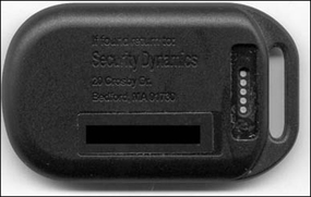
Often, products will have development or programming interfaces that are not meant for everyday consumer use, but can benefit a potential attacker immensely. Take note of any out-of-the-ordinary connector types, peculiar access doors or holes, or evidence in the chassis that may indicate a prior location of a door or access panel for debugging or development activities. These clues will help reveal the location of possible de-populated debugging points or programming interfaces. Figure 14.3 and Figure 14.4 show examples of two products that have some type of programming or test interface available to all users: a hardware authenticator key fob and a PDA. The test points shown in Figure 14.3, the five brass-colored dots, are accessible by simply removing a small plastic sticker on the back of the device housing. Once the test points have been probed or used, the sticker can be replaced, leaving no signs of tampering. In Figure 14.4, the seven holes in the plastic housing (shown on the bottom of the right image) allow the test points to be accessed when the case is closed.

If such interfaces are transmitting critical information, or used for device programming or control with minimal or no security/authentication, the product could easily be hacked or modified. For example, the Palm Operating System transmits an obfuscated version of the system password over the serial port during a HotSync operation. (See the “Cryptanalysis and Obfuscation Methods” section for more details.)
Protocol Analysis
Data transfer can occur either between components at board-level or through an external interface to the outside world. Understanding the methods of data transfer used is a crucial part of hardware hacking and, if successful, you may be able to retrieve critical information, or control or reprogram the product.
Unknown protocols can be monitored with the use of a digital oscilloscope or logic analyzer (see the “What Tools Do I Need?” section for more information). With these tools, the target transmission sequences can be captured and stored for later analysis. Dedicated protocol analyzers could be used on known protocols. One attack against a known protocol would be to generate malformed or intentionally bad packets (using the traffic generation features of a protocol analyzer) and observe the results. If the software controlling the product is not correctly programmed to handle errors or illegal packets (in other words, not conforming to the protocol specification), a failure may trigger an unintended operation that is useful to the attacker. A large number of protocols and specifications exist for various data transfer mechanisms.
The Universal Serial Bus (USB) specifications (www.usb.org) provide technical details to understand USB requirements (mechanical and electrical) and design USB-compatible products. USB Snoopy (www.jps.net/˜koma) is a Windows-based monitoring tool/protocol analyzer that serves as a low-cost alternative to using a hardware-based solution. This tool captures and displays all USB data traffic and is extremely useful for determining what information a product is transmitting to the host computer and vice-versa. Using such a tool can help you figure out what commands or what format of data the device is expecting, so you can attempt to send the device “undocumented” commands or data and discover any anomalies.
Infrared (IR) is another form of wireless that is designed for close-quarters, point-to-point communications. IR is commonly used on PDAs and mobile telephones in order to transfer phone number, memo pad, date book, and to-do list information between the device and a host computer. The Infrared Data Association (IrDA) standard (www.irda.org) is the most popular of interconnection standard for Infrared. The standard supports a broad range of appliances, computing and communications devices.
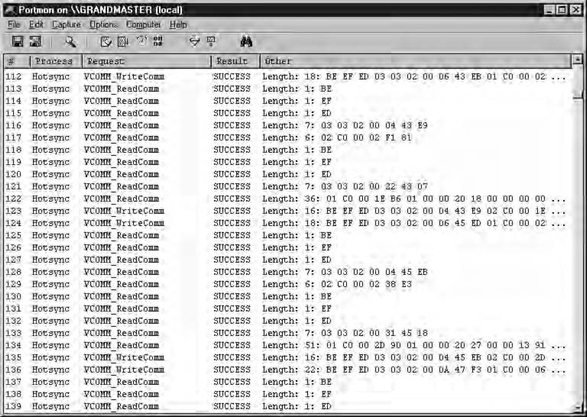
In the past few years, serial (RS232) and parallel connections have become less common as products and peripherals are replaced with newer USB and IR interfaces. However, transmitting data in a generic serial or parallel format is extremely easy and requires minimal overhead. PortMon by Sysinternals (www.sysinternals.com/ntw2k/freeware/portmon.shtml) monitors and displays all of a system’s serial and parallel port activity. As with USB Snoopy, this tool is useful for examining data transfer between a host computer and target device. Figure 14.5 shows a screenshot of PortMon logging the data transfer between a PDA and desktop serial port.
Wireless technologies are becoming very popular, and are being implemented in an increasing number of products. Much of the various protocols’ wireless traffic is sent in the clear, which allows an attacker with minimal resources to monitor the traffic. Such is the case for paging protocols (POCSAG and FLEX), air traffic control (ACARS), police and mobile data terminals (MDC4800), and particular implementations of two-way pagers such as Research In Motion’s BlackBerry (Mobitex). The most popular protocol for networking-related wireless products is 802.11b wireless Ethernet (http://standards.ieee.org/getieee802). Airopeek, a software-based tool from WildPackets (www.wildpackets.com/products/airopeek), is designed for analyzing the network traffic on 802.11b wireless networks. Another software-based 802.11b wireless monitoring tool and analyzer is Sniffer Wireless from Sniffer Technologies (www.sniffer.com/products/sniffer-wireless). Bluetooth (www.bluetooth.com) and HomeRF (www.homerf.org) are two consumer product-oriented wireless protocols, both of which operate in the 2.4GHz band and use Frequency Hopping Spread Spectrum (FHSS).
For a reference on Ethernet and network protocol analysis, Comer’s Internetworking with TCP/IP volume 1 – Principles, Protocols, and Architecture, published by Prentice-Hall, provides an introduction and details to the TCP/IP network protocols. Other network technologies are also discussed.
Electromagnetic Interference and Electrostatic Discharge
All electronic devices generate electromagnetic interference (EMI) in one form or another. This is a by-product of electrical properties, printed circuit board layout, and component value variations. This phase of analysis aims to determine how much EMI a device produces and whether or not it is useful for attack purposes.
Hardware hacking attacks by measuring EMI were first hypothesized and detailed by Wim van Eck in his paper Electromagnetic Radiation from Video Display Units: An Eavesdropping Risk? (Computers & Security, Vol. 4, 1985, www.jya.com/emr.pdf). This paper describes the results of research into the possibility of eavesdropping on video display units by picking up and decoding the electromagnetic interference, now known as “van Eck monitoring.” John Young’s “TEMPEST Documents” Web page (http://cryptome.org/nsa-tempest.htm) provides a wealth of information and recently unclassified government documents on van Eck monitoring and government shielding requirements (known as “TEMPEST”). Much of the TEMPEST shielding information is still classified by the United States Government. With the right antenna and receiver, EMI emanations can be intercepted from a remote location and redisplayed (in the case of a monitor screen) or recorded and replayed (such as with a printer or keyboard) by the attacker.
In recent times, EMI measurements have become a popular technique for smart card analysis, since they can yield interesting information about processing power and cryptographic operations (which might lead to discovery of certain portions of the cryptographic key). Rao and Rohatgi’s EMPowering Side-Channel Attacks (www.research.ibm.com/intsec/emf.html) provides preliminary results of compromising information via EMI emanations from smart cards. This research is based on power analysis and Kocher, Jaffe, and Jun’s Differential Power Analysis paper (Advances in Cryptology: Proceedings of Crypto ′99, 2000, www.cryptography.com/dpa/Dpa.pdf) in which the electrical activity of a smart card is monitored and advanced statistical/mathematical methods are used to determine secret information stored in the device. These types of EMI and power analysis attacks are useful on small, portable devices such as smart cards, authentication tokens, and secure cryptographic devices. Larger devices, such as desktop computers and network appliances, might generate too much EMI to be able to measure specific, minute changes as cryptographic functions are being processed.
EMI measurements and van Eck monitoring are referred to as passive attacks. An active attack consists of directing high-energy RF (HERF) signals at a particular product to analyze susceptibility to EMI/RF noise. This can disrupt the normal operation of digital equipment such as computers and navigational equipment. Large amounts of HERF often damage electrical devices, however; and generally don’t provide useful results for hardware hacking (unless the objective is to destroy a product). Another active attack consists of injecting static electricity into a device in order to cause failures. Electrostatic discharge (ESD) protection components are often designed into external connectors and contacts to reduce the chance of failure (by using diodes or Transient Voltage Suppressor devices). One attack uses an ESD simulator tool to generate a high voltage spike and inject it into a device’s external interface or keypad in hopes of causing an unexpected or unintended condition (by causing the program counter to jump to a different code portion or change the values on the address or data bus, which would confuse the operating program). However, unless the injection of HERF or ESD can be reproduced in a controlled manner, the results may be too unpredictable to be useful.
Analyzing the Product Internals: Electrical Circuit Attacks
Many of the weaknesses, security vulnerabilities, and design flaws of a product are identified during the electrical circuit analysis stage. At this point, the product has (hopefully) been opened up and we have complete access to the circuitry and other internal components.
Reverse-engineering the Device
The schematic is essentially an electrical operation road map and forms the base for determining any electrical-related vulnerabilities. Reverse-engineering a complete system can be time consuming for products larger than a small portable device (such as an authentication token). For larger products, any schematics and technical repair manuals that might be available from the product vendor would be extremely helpful.
When reverse-engineering the target product, it is necessary to determine the part numbers and device functionality of most, if not all, of the components. Understanding what the components do may provide details for particular signal lines that may be useful for active probing during operation. Nearly all integrated circuit (IC) vendors post their component data sheets on the Web for public viewing, so simple searches will yield a decent amount of information. “IC MASTER Online” (www.icmaster.com) provides part number searches, pinout and package data, logos, application notes, second sources, and cross-references for over 135,000 base components from over 345 manufacturers. Drawing the schematic can be done by hand, but a schematic entry system such as Cadence Design Systems’ OrCAD Capture (www.orcad.com/Product/Schematic/Capture/default.asp), makes the task much more manageable. Physically examining the circuit board can reveal unpopulated debug ports, reset buttons, or logic analyzer probe headers for bus analysis, all of which can prove useful for active data gathering.
Figure 14.6 shows the circuit board from an Aladdin Knowledge Systems’ eToken R1 USB hardware authentication device. It is easy to pick out the major components: the microprocessor, denoted as CY7C63001A, on the left, and an external memory device to the right of that. The backside of the board (shown on the bottom) has some supporting glue circuitry, including some capacitors, a timing crystal, and a microprocessor reset IC. There is a green light-emitting diode (LED) on the right edge of the board and the obvious USB connector on the left. Reverse-engineering the design and creating a schematic (Figure 14.7) took about one hour. In this particular example, our first attack was to attempt to read the contents of the external memory device using a device programmer, which provided us with enough information to successfully defeat the security features and gain access to private data. Full details of this attack can be read in Kingpin’s “Attacks on and Countermeasures for USB Hardware Token Devices” (Proceeding of the Fifth Nordic Workshop on Secure IT Systems, www.atstake.com/research/reports/usb_hardware_token.pdf).


Figure 14.7 Resultant Reverse-engineered Schematic from Figure 14.6
Basic Techniques: Common Attacks
Once the schematic has been drawn to the best of our knowledge, we can begin to identify and hypothesize on possible attack vectors. Can certain areas of the circuitry be accessed without opening up the entire device? This knowledge is especially useful if there are tamper mechanisms covering certain areas, and may lead to quick attacks rather than having to completely open the unit. Some of the most basic attacks are related to data extraction from microprocessors or external memory components (see the “Memory Retrieval” section) in which critical information may be read and/or modified to the attacker’s advantage. Information can also be gleaned by analyzing the internal address and data bus lines, which is often achieved with a logic analyzer or digital oscilloscope. Varying the voltage supplied to the circuit or changing the temperature environment (such as by applying direct heat or cold to an individual component or making a more general change in ambient operating temperature) to bring the device outside of normal operating conditions may cause beneficial side effects.
Anderson and Kuhn’s Low Cost Attacks on Tamper Resistant Devices (Security Protocols, 5th International Workshop, 1997, www.cl.cam.ac.uk/˜mgk25/tamper2.pdf) describes a number of techniques that low-budget attackers can use to break smart cards and “secure” microcontrollers.
Device Packaging
Making note of the various integrated circuit component package types and how they are protected (with metal shielding or encapsulation, for example) is also helpful. Some packages allow easy access to the pins in order to probe the device, such as with Dual Inline Package (DIP), Small Outline Integrated Circuit (SOIC), or Plastic Leadless Chip Carrier (PLCC). As the spacing of the pins becomes more dense-as with Thin Shrink Small Outline Package (TSSOP), probing individual pins becomes more difficult without using high-quality probes or a test clip/adapter such as one provided from Emulation Technology (www.emulation.com).
Ball Grid Array (BGA) packaging has all of the device leads located underneath the chip, making it extremely difficult to access the inner pins. It would be necessary to remove the chip and create an extension or adapter board if probing is required. BGA devices are becoming more popular due to their small footprint and low failure rates. The testing process (done during product manufacturing) is more expensive than other package types due to the fact that X-rays are often used to verify that the solder has properly bonded to each of the ball leads.
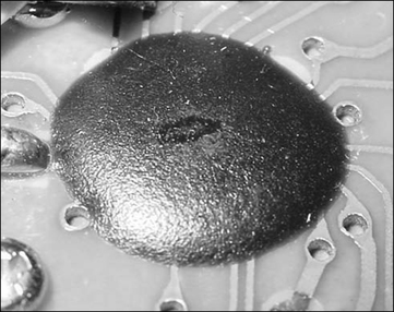
With Chip-on-Board (COB) packaging, the silicon die of the integrated circuit is mounted directly to the PCB and protected by epoxy encapsulation (Figure 14.8). The “Advanced Techniques” section provides more information on gaining access to and analyzing COB devices.
Memory Retrieval
In many products, including those designed for security purposes, simple external memory devices are used to store such data as configuration information, secret components (passwords, PINs, cryptographic keys), or temporary variables and can easily be retrieved using a device programmer. For example, Kingpin’s MAC Address Cloning (www.atstake.com/research/reports/mac_address_cloning.pdf) details modifying Network Interface Cards (NICs) to change the physical 6-byte Media Access Control (MAC) address which is stored in an unprotected Serial Electrically Erasable Programmable Read-Only Memory (EEPROM) device. Serial EEPROMs are extremely common in the engineering industry and require minimal circuitry to read/write to them. Due to the design of Serial EEPROMs, it is possible to attach a device programmer to the device, while it is still attached to the circuit, and read/write at will. This is extremely useful for monitoring how the device is using its memory, and to determine what type of data is being stored there. For example, by repeatedly changing the user password on an authentication device and reading the EEPROM after each change, it is possible to determine if the password is being stored in the device, where in memory it is being stored, and what type of obfuscation or encoding (if any) is done on the password before storage.
Reading Random Access Memory (RAM) or other volatile storage areas while the device is in operation may yield useful temporarily-stored data or plaintext components. This is more difficult, however, as changing the address and data buses of the device during operation may cause bus faults and device failure.
Most memory devices, including RAM, ROM, and Flash memory, are notoriously insecure. Some memory devices employ security features to prevent regular device programmers from reading stored data, such as physical fuses on ROMs and boot-block protection in Flash. The Dallas Semiconductor DS2432 EEPROM (http://pdfserv.maxim-ic.com/arpdf/DS2432.pdf) is an example of a secure memory device that uses the Secure Hash Algorithm (SHA-1) and a user-provided write-only secret to protect stored data. Most other EEPROM devices, however, do not have this type of functionality. Advanced techniques such as silicon die analysis can often be used to thwart these protection methods.
In Data Remanence in Semiconductor Devices (Proceedings of the Tenth USENIX Security Symposium, 2001, www.usenix.org/publications/library/proceedings/sec01/gutmann.html), Gutmann has shown that it is extremely difficult to securely and totally erase data from RAM and non-volatile memory. This means that remnants of temporary data, cryptographic keys, and other secrets may possibly exist and still be retrievable from devices long after power has been removed or after the memory contents have been rewritten. Retrieving data in this manner requires advanced equipment usually available in academic environments.
Timing Attacks
Timing attacks rely on changing or measuring the timing characteristics of the circuitry and usually fall into one of two categories: Active timing attacks are invasive attacks requiring physical access to the clock crystal or other timing circuitry. The main goal is to vary the clock frequency to induce failure or unintended operation. Circuits that make use of the clock crystal for accurate timing, such as a time-based authentication token, could be attacked to “speed up” or “slow down” time based on the clock input. Slowing down a device can also help for debugging and analysis that might not be possible at higher rates.
Passive timing attacks are non-invasive measurements of computation time in order to determine data or device/cryptographic operation. By going with the hypothesis that different computational tasks take different amounts of time, it might be possible to determine secret components or break the cryptosystem of the device under attack, as discussed in Timing Attacks on Implementations of Diffie-Hellman, RSA, DSS, and Other Systems (www.cryptography.com/timingattack/timing.pdf) by Paul Kocher.
Advanced Techniques: Epoxy Removal and IC Delidding
Encapsulation of critical components using epoxy or other adhesives is commonly done to prevent tampering and device access (the microprocessor shown in Figure 14.9 is covered by a hard epoxy encapsulate to prevent probing). There are many different types of epoxies and resins that can be used to provide component protection. Some of this material can be dissolved or removed using chemicals (such as Methylene Chloride or Fuming Nitric Acid). A quick-turn solution is to use a Dremel tool or drill with a wooden bit (such as the shaft of a cotton swab or a toothpick). Moving the drill lightly along the epoxy surface will weaken and thin the bonding material. It is recommended that you take proper precautions and wear protective gear for this stage of the attack. Once the epoxy is removed from the component, you may be able to begin probing the device.

For more complicated product designs, IC delidding and analysis of the silicon die might need to take place (especially if security features are in place to prevent proper reading from a memory device as described in the “Memory Retrieval” section). The goal of delidding is to get access to the actual die of the integrated circuit (which could be a microprocessor, analog or digital memory, or programmable logic). IC delidding is extremely difficult without the use of proper tools because hazardous chemicals are often required and the underlying die is very fragile. Decapsulation products are offered by companies such as B&G International (www.bgintl.com) that will aid in certain types of epoxy removal.
Silicon Die Analysis
Once the die is accessible, a high-powered microscope can be used to analyze the actual die image. This can be done to retrieve data contents/program code from ROM, or determine address decoding logic or state machine functionality. Kömmerling and Kuhn’s Design Principles for Tamper-Resistant Smartcard Processors (Proceedings of the USENIX Workshop on Smartcard Technology, 1999, www.cl.cam.ac.uk/˜mgk25/sc99-tamper.pdf) details techniques to extract software and data from smart card processors, including manual microprobing, laser cutting, focused ion-beam manipulation, glitch attacks, and power analysis. Much of this attack research is based on Beck’s Integrated Circuit Failure Analysis – A Guide to Preparation Techniques book (John Wiley & Sons, 1998) which details techniques for opening the package/chip insulation, etching procedures for removing layers of chip structure, and health and safety procedures.
Figure 14.10 shows a scan of a die from a typical EPROM, whose gates are set with electrical pulses and erased with direct ultraviolet light. Depending on the silicon technology used, further magnification and silicon layer removal will reveal an image similar to Figure 14.11. In this image, there are 16 columns and 10 rows to provide 160 bits of storage. Every bit is represented by either a present or missing connection, representing a ‘1’ or a ‘0’, respectively. For example, the top row corresponds to “0000010011100001”.

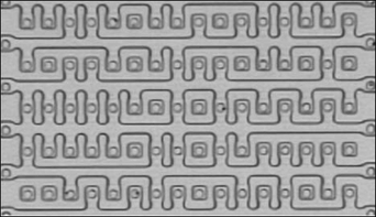
Figure 14.11 Magnified Portion of a ROM Die Showing Actual Data Bits Photo courtesy of ADSR Ltd., www.adsr.de
Much of the die analysis attacks require advanced tools and equipment that are often available in academic laboratories. Reverse-engineering services are offered by companies such as Semiconductor Insights (www.semiconductor.com), that aid in functional investigation, extraction, and simulation of ICs. They can also analyze semiconductor and fabrication processes, techniques and materials. Such services are useful if local resources are not immediately available.
Cryptanalysis and Obfuscation Methods
Products and systems commonly use simple obfuscation to protect secret data components that are stored in memory. Simple obfuscation and reversible transforms lull the user into a false sense of security. Even solid cryptographic algorithms are at risk if the secret components can be retrieved and identified.
Once data is retrieved from a device, it may be necessary to analyze the contents to determine what the real data values are. Knowing the simple cryptographic algorithms (described in Chapter 6) and commonly used obfuscation techniques will aid in such recovery. There are also more complicated data protection/obfuscation mechanisms, such as Tamper Resistant Software by Cloakware Corporation (www.cloakware.com). Applied Cryptography (John Wiley & Sons, 1996) by Bruce Schneier can also be of help; it describes the history of cryptography and presents dozens of cryptographic protocols, algorithms, and source code, and is a great starting point when attempting cryptanalysis of data you have retrieved from a hardware device.
One example of a weak, reversible encoding scheme is the one used by Palm OS to protect a PDA’s system password: the password is obfuscated and stored in system memory. It is also transmitted through the serial or Infrared port during a HotSync operation, which can easily be monitored. As shown in Kingpin’s “Palm OS Password Retrieval and Decoding” advisory (www.atstake.com/research/advisories/2000/a092600-1.txt), it is possible to easily determine the actual password: The password is set by the legitimate user with the Palm “Security” application; the maximum length of the ASCII password is 31 characters. Regardless of the length of the ASCII password, the resultant encoded block is always 32 bytes. Two methods are used to encode the ASCII password, depending on its length. Our example will look at the scheme for passwords of four characters or less. By monitoring the serial port during a HotSync operation (using PortMon) and comparing the encoded password blocks of various short passwords, it was determined that a 32-byte constant was simply being Exclusive ORed (XOR, a logical operation) against the ASCII password block. To decode the obfuscated password back into the original password, the encoded block is simply XORed with the constant bock.
Let A = Original ASCII password
Let B = 32-byte constant block
Let C = 32-byte encoded password block
For passwords of length 4 characters or less, we can define B to be the following:
09 02 13 45 07 04 13 44 0C 08 13 5A 32 15 13 5D
D2 17 EA D3 B5 DF 55 63 22 E9 A1 4A 99 4B 0F 88
First, we will calculate the starting index, j, which determines where in the constant block the XOR operation will begin. j is computed by adding the length of the original password (for example, we will use a password of ‘test’, so the length is 4) to the ASCII decimal value of the first character of the password (‘t’ is equal to 116 decimal) modulo 32. In this example, the XOR operation will begin with the 24th character in the 32-byte constant block.
Next, a simple loop occurs, repeating 32 times and XORing the original ASCII password with the 32-byte constant block (indexed by j, as calculated above), storing the result in a new 32-byte array: C, the encoded password block.
![]()
C, the resultant encoded password block of ASCII password ‘test’, is shown below. Note that only 4 of the bytes differ from the constant block above. Those represent the encoded version of the password.
56 8C D2 3E 99 4B 0F 88 09 02 13 45 07 04 13 44
0C 08 13 5A 32 15 13 5D D2 17 EA D3 B5 DF 55 63
Knowing both the constant and encoded blocks allows us to easily determine the original ASCII password. We can do this by comparing both blocks, rotating the constant block until all similar bytes line up, and then individually XORing the bytes that differ. For example, 0×56 XOR 0×22 = 0×74 (which corresponds to ‘t’), 0×8C XOR 0×E9 = 0×65 (‘e’), 0×D2 XOR 0×A1 (‘s’), and so on.
What Tools Do I Need?
The cache of tools required for hardware hacking is very different than those used for network or software analysis. It is not necessary to have a world-class laboratory in order to conduct most levels of hardware hacking. Advanced techniques obviously require more advanced equipment (such as chemicals for epoxy removal and IC delidding), but you can carry out many experiments with a minimal amount of resources.
Starter Kit
The following “starter kit” tools are required for the hardware hacker’s arsenal:
![]() Digital Multimeter Commonly referred to as the Swiss Army Knife of electrical engineering measurement tools. These (usually) portable devices provide a number of measurement functions, including AC/DC voltage, resistance, capacitance, current, and continuity. More advanced models also include frequency counters, graphical displays, and digital oscilloscope functionality. Example: Fluke 110, www.fluke.com. Approximate price range: $20 – $500.
Digital Multimeter Commonly referred to as the Swiss Army Knife of electrical engineering measurement tools. These (usually) portable devices provide a number of measurement functions, including AC/DC voltage, resistance, capacitance, current, and continuity. More advanced models also include frequency counters, graphical displays, and digital oscilloscope functionality. Example: Fluke 110, www.fluke.com. Approximate price range: $20 – $500.
![]() Soldering Station Soldering tools come in many shapes and sizes, ranging from a simple stick iron to a full-fledged rework station. More advanced models include adjustable temperature control, automatic shut-off, and interchangeable tips for various component package types and soldering needs. Example: Weller WES50, www.coopertools.com/brands/weller. Approximate price range: $10 – $500.
Soldering Station Soldering tools come in many shapes and sizes, ranging from a simple stick iron to a full-fledged rework station. More advanced models include adjustable temperature control, automatic shut-off, and interchangeable tips for various component package types and soldering needs. Example: Weller WES50, www.coopertools.com/brands/weller. Approximate price range: $10 – $500.
![]() Device Programmer Used to read and write memories (RAM, ROM, EPROM, EEPROM, Flash), microcontrollers, and programmable logic devices. Extremely useful to extract program code and stored data. Example: BP Microsystems BP-1600, www.bpmicro.com. Approximate price range: $10 (for home built) – $1000.
Device Programmer Used to read and write memories (RAM, ROM, EPROM, EEPROM, Flash), microcontrollers, and programmable logic devices. Extremely useful to extract program code and stored data. Example: BP Microsystems BP-1600, www.bpmicro.com. Approximate price range: $10 (for home built) – $1000.
![]() Miscellaneous Equipment Heat Gun, Screwdrivers, Wire Strippers, Wire Clippers, Needle Nose Pliers, Test Leads/Alligator Clips, Protective Gear (Mask, Goggles, and Smock), Solder Sucker/Solder Wick
Miscellaneous Equipment Heat Gun, Screwdrivers, Wire Strippers, Wire Clippers, Needle Nose Pliers, Test Leads/Alligator Clips, Protective Gear (Mask, Goggles, and Smock), Solder Sucker/Solder Wick
Advanced Kit
Depending on the complexity of the target product and your determination to successfully hack it, additional resources may be necessary. Much of this equipment is expensive (upwards of $10K+) but can be rented or leased from a test equipment rental firm (such as Technology Rentals and Services, www.trsonesource.com) on a weekly or monthly basis. Academic laboratory environments will often have these tools available as well.
![]() Digital Oscilloscope Provides a visual display and storage of electrical signals and how they change over time. The digital oscilloscope is arguably the most important of advanced measurement tools. Example: Tektronix TDS3034B, www.tektronix.com/Measurement/scopes, approximate price range: $1000 (used) – $10,000.
Digital Oscilloscope Provides a visual display and storage of electrical signals and how they change over time. The digital oscilloscope is arguably the most important of advanced measurement tools. Example: Tektronix TDS3034B, www.tektronix.com/Measurement/scopes, approximate price range: $1000 (used) – $10,000.
![]() Desoldering Station Useful for easy removal or replacement of components from printed circuit boards. Simple component removal can be achieved with a soldering iron and solder sucker, but often leads to excessive heating of the circuit board (which should be avoided) and is difficult for surface-mount and fine-pitch components. Example: Pace ST75, www.paceworldwide.com. Approximate price range: $100 – $1000.
Desoldering Station Useful for easy removal or replacement of components from printed circuit boards. Simple component removal can be achieved with a soldering iron and solder sucker, but often leads to excessive heating of the circuit board (which should be avoided) and is difficult for surface-mount and fine-pitch components. Example: Pace ST75, www.paceworldwide.com. Approximate price range: $100 – $1000.
![]() Dremel Tool Extremely useful carving tool for detailed and delicate work. Helpful for opening housings and removing epoxy coatings (with a wooden dowel as a drill bit). Some models support rotation speeds from single digit revolutions per second up to tens of thousands. Many various bit types (drills, sanding, carving, engraving), accessories, and attachments are available. Example: Dremel 395 Variable-Speed MultiPro, www.dremel.com. Approximate price range: $50 – $100.
Dremel Tool Extremely useful carving tool for detailed and delicate work. Helpful for opening housings and removing epoxy coatings (with a wooden dowel as a drill bit). Some models support rotation speeds from single digit revolutions per second up to tens of thousands. Many various bit types (drills, sanding, carving, engraving), accessories, and attachments are available. Example: Dremel 395 Variable-Speed MultiPro, www.dremel.com. Approximate price range: $50 – $100.
![]() PCB Etching Kit Kit to create printed circuit boards (useful for test jigs or electronic projects). This process is time consuming and uses hazardous chemicals. Radio Shack provides a kit that contains two 3” x 4.5” copper-clad circuit boards, resist-ink pen, etching and stripping solutions, etching tank, 1/16” drill bit, polishing pad, and complete instructions. PCB etching materials can also be purchased separately at any electronics distributor. Example: Radio Shack PC Board Kit, www.radioshack.com/searchsku.asp?find=276-1576. Approximate price range: $10 – $50.
PCB Etching Kit Kit to create printed circuit boards (useful for test jigs or electronic projects). This process is time consuming and uses hazardous chemicals. Radio Shack provides a kit that contains two 3” x 4.5” copper-clad circuit boards, resist-ink pen, etching and stripping solutions, etching tank, 1/16” drill bit, polishing pad, and complete instructions. PCB etching materials can also be purchased separately at any electronics distributor. Example: Radio Shack PC Board Kit, www.radioshack.com/searchsku.asp?find=276-1576. Approximate price range: $10 – $50.
![]() Spectrum Analyzer Graphically displays the signal power over a frequency domain. Commonly used for wireless analysis to determine the transmitting strength and frequency of a device. Example: Tektronix FSEA20, www.tektronix.com/Measurement/commtest/index/prodindex_spectrum.html. Approximate price range: $10,000 (used) – $100,000.
Spectrum Analyzer Graphically displays the signal power over a frequency domain. Commonly used for wireless analysis to determine the transmitting strength and frequency of a device. Example: Tektronix FSEA20, www.tektronix.com/Measurement/commtest/index/prodindex_spectrum.html. Approximate price range: $10,000 (used) – $100,000.
![]() ESD Simulator Generates a high voltage spikes (around 30kV for air discharge and 25kV for contact discharge) used to test for failures or compliance to standards. Injecting electrostatic discharge (ESD) into a circuit can cause damage or unintended operations that may lead to leakage of secret components. Example: Haefely Trench PESD 1600, www.haefely.com. Approximate price range: $5,000 – $10,000.
ESD Simulator Generates a high voltage spikes (around 30kV for air discharge and 25kV for contact discharge) used to test for failures or compliance to standards. Injecting electrostatic discharge (ESD) into a circuit can cause damage or unintended operations that may lead to leakage of secret components. Example: Haefely Trench PESD 1600, www.haefely.com. Approximate price range: $5,000 – $10,000.
![]() Logic Analyzer Used to develop and debug digital systems. Provides a visual display of the past and present state of multiple digital inputs. Captures signals based on predefined trigger/stimulus settings. Example: Tektronix TLA600, www.tektronix.com/Measurement/logic_analyzers/home.html. Approximate price range: $5,000 (used) – $50,000.
Logic Analyzer Used to develop and debug digital systems. Provides a visual display of the past and present state of multiple digital inputs. Captures signals based on predefined trigger/stimulus settings. Example: Tektronix TLA600, www.tektronix.com/Measurement/logic_analyzers/home.html. Approximate price range: $5,000 (used) – $50,000.
![]() Frequency Counter/Field Strength Meter Near field receiver used to measure the frequency of an input signal or the strongest RF signal of a nearby transmitter. Commonly used for wireless analysis. Example: Optoelectronics CD100, www.optoelectronics.com. Approximate price range: $100 – $500.
Frequency Counter/Field Strength Meter Near field receiver used to measure the frequency of an input signal or the strongest RF signal of a nearby transmitter. Commonly used for wireless analysis. Example: Optoelectronics CD100, www.optoelectronics.com. Approximate price range: $100 – $500.
![]() Protocol Analyzer Measurement tool to monitor and decode digital communication traffic. Many support graphical data display and automatic data configuration sensing (useful for unknown protocol types). Examples: Comcraft (RS-232) www.comcraftfr.com/dlm200.htm, CATC (Bluetooth, USB, IEEE-1394, Ethernet, InfiniBand) www.catc.com, Catalyst Enterprises (USB, ISA, PCI, MiniPCI, PCI-X, CompactPCI) www.catalyst-ent.com. Approximate price range: $500 – $50,000.
Protocol Analyzer Measurement tool to monitor and decode digital communication traffic. Many support graphical data display and automatic data configuration sensing (useful for unknown protocol types). Examples: Comcraft (RS-232) www.comcraftfr.com/dlm200.htm, CATC (Bluetooth, USB, IEEE-1394, Ethernet, InfiniBand) www.catc.com, Catalyst Enterprises (USB, ISA, PCI, MiniPCI, PCI-X, CompactPCI) www.catalyst-ent.com. Approximate price range: $500 – $50,000.
![]() In-Circuit Emulator Engineering/development tool used to monitor and emulate all processor activities on a device. The In-Circuit Emulator (ICE) connects to a host PC and replaces the microprocessor of the unit under test. It enables real-time tracing of instruction calls, register states, and processor activity, but appears to the device that an actual microprocessor is in place. An ICE can be helpful for reverse-engineering of product/code functionality if the firmware is not accessible (as in the ROM is protected by tamper mechanisms). In-Circuit Emulators exist for all popular processor cores. Example: Microtek Low-Power Pentium ICE, www.microtekintl.com/MainSite/Processors/LowPwrPentium.htm. Approximate price range: $500 – $50,000.
In-Circuit Emulator Engineering/development tool used to monitor and emulate all processor activities on a device. The In-Circuit Emulator (ICE) connects to a host PC and replaces the microprocessor of the unit under test. It enables real-time tracing of instruction calls, register states, and processor activity, but appears to the device that an actual microprocessor is in place. An ICE can be helpful for reverse-engineering of product/code functionality if the firmware is not accessible (as in the ROM is protected by tamper mechanisms). In-Circuit Emulators exist for all popular processor cores. Example: Microtek Low-Power Pentium ICE, www.microtekintl.com/MainSite/Processors/LowPwrPentium.htm. Approximate price range: $500 – $50,000.
Example: Hacking the iButton Authentication Token
The Dallas Semiconductor DS1991 MultiKey iButton (www.ibutton.com) is a hardware authentication token that has three internal secure data areas, each protected by a distinct password. Depending on the application, the iButton can be used for cashless transactions, user authentication, or access control; and the secure data could include financial information, monetary units, or user registration/identification information.
The goal of this example is to attempt to recover either the passwords or the secure data within the device without having legitimate credentials. By communicating with the device via a PC serial port and using some basic cryptanalysis techniques (similar to that discussed in the “Cryptanalysis and Obfuscation Methods” section), we discover a vulnerability that potentially allows an attacker to determine the passwords used to protect these secure areas, thus gaining access to the protected data. This example is based on Kingpin’s DS1991 MultiKey iButton Dictionary Attack Vulnerability advisory (www.atstake.com/research/advisories/2001/a011801-1.txt).
Experimenting with the Device
The DS1991 contains 1,152 bits of non-volatile memory split into three 384-bit (48-byte) containers known as subkeys. Each subkey is protected by an independent 8-byte password. Only the correct password will grant access to the data stored within a subkey area and return the data. If an incorrect password is given, the DS1991 will return 48-bytes of random data intended to prevent an attacker from comparing it against a known constant value. Dallas Semiconductor marketing literature (www.ibutton.com/software/softauth/feature.html) states that “false passwords written to the DS1991 will automatically invoke a random number generator (contained in the iButton) that replies with false responses. This eliminates attempts to break security by pattern association. Conventional protection devices do not support this feature.”
By using the iButton-TMEX software (www.ibutton.com/software/tmex/index.html), which includes an iButton Viewer to explore and connect to iButton devices, it was determined that the data returned on an incorrect password attempt is not random at all and is calculated based on the input password and a constant block of data stored within the DS1991 device. Figure 14.12 shows the data contents of a DS1991 device. Note the identical values returned for Subkey IDs 1 and 2 when an incorrect password of “hello” is entered.

The returned data has no correlation to the actual valid password, which is stored in the DS1991’s internal memory. The constant block of data, which is a 12k array containing 256 entries of 48-bytes each, is constant across all DS1991 devices and has no relation to the actual contents of the subkey memory areas. This means that for any given character (1 byte = 256 possibilities), there is a unique 48-byte response sent back from the iButton device. To determine what comprised that constant block, Dallas Semiconductor wrote a test program (based on the TDS1991.C sample code, ftp://ftp.dalsemi.com/pub/auto_id/softdev/tds1991.zip) to simply set the password 256 times, ranging from 0x00 to 0xFF, and record the response. The serial port was monitored to view the responses from the iButton device. It was then a matter of puzzle-solving to determine what the responses would be for longer passwords. By pre-computing the return value expected for an incorrect password attempt, it is possible to determine if a correct password was entered. This is due to the fact that, if the password is correct, the data returned by the DS1991 will be the actual data stored in the subkey, not the “incorrect password” response.
The transaction time is limited to 0.116 seconds for each password attempt by the computational speed of the DS1991 and the bus speed of its 1-Wire interface. Because of this, it is not possible to perform an exhaustive brute-force search of the entire 64-bit password keyspace, or that of only ASCII-printable characters (which would require approximately 22,406,645 years). However, it is still possible to perform a dictionary attack against the device using a list of commonly used passwords.
Reverse-engineering the “Random” Response
By comparing the 48-byte “random” device responses of various known incorrect passwords, it was determined that they were computed in a simple loop, as shown below. Although the code may appear complex, we are essentially just XORing a number of constant strings together.
Let A_j be the jth byte of A, the 8-byte password (padded with 0x20 if less than 8-bytes)
Let B_k be the kth entry of B, the 12kB constant block (256 entries each 48-bytes in length)
Let C_m be the mth byte of C, the 48-byte response (initialized to 0x00)
for (j = 0; j < 8; ++j) // For each remaining character in p/w.

There is an additional step taken if the last character of the password (A_7) is signed (greater than 0x7F). If this is the case, the pre-computed subkey value is XORed against another constant block containing 128 entries of 48-bytes each. It is unclear why iButton performs this step, but it is possibly to add an additional level of obscurity to the “random” response.
As shown in the code above, the constant block is used to retrieve a 48-byte string for each byte of the entered password. Each string is XORed together to produce the final response that the iButton device returns if the password is incorrect. For the example shown below, let’s use a password of “hello” (padded up to 8 characters with 0x20, which is a blank space) and compute the 48-byte “incorrect password” string. In the interest of space, we will only look at the first 16-bytes of the resultant 48-byte response.
Let A = “hello” = 68 65 6C 6C 6F 20 20 20
B_68 (‘h’) = D8 F6 57 6C AD DD CF 47 CC 05 0B 5B 9C FC 37 93 …
B_65 (‘e’) = 03 08 DD C1 18 26 36 CF 75 65 6A D0 0F 03 51 81 …
B_6C (‘l’) = A4 33 51 D2 20 55 32 34 D8 BF B1 29 40 03 5C 9C …
B_6C (‘l’) = A4 33 51 D2 20 55 32 34 D8 BF B1 29 40 03 5C 9C …
B_6F (‘o’) = 45 E0 D3 62 45 F3 33 11 57 4C 42 0C 59 03 33 98 …
B_20 (‘’) = E0 2B 36 F0 6D 44 EC 9F A3 D0 D5 95 E3 FE 5F 7B …
B_20 (‘’) = E0 2B 36 F0 6D 44 EC 9F A3 D0 D5 95 E3 FE 5F 7B …
B_20 (‘’) = E0 2B 36 F0 6D 44 EC 9F A3 D0 D5 95 E3 FE 5F 7B …
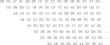
The final pre-computed “random” response is calculated by XORing all of the above lines together, keeping the most significant 48 bytes. Note that this string is the hexadecimal representation of the “garbage” in Figure 14.12 that was returned when “hello” was entered as an incorrect password:
D8 F5 FB 26 4B 46 03 9B CC 2E 68 82 22 F7 F3 2B …
The DS1991 device will return the 48-byte “incorrect password” string if the given password is incorrect (as demonstrated by our example). The pre-computed value will always be the same for any device that is given the same password. Because of this, if the pre-computed value matches the response returned from the DS1991, we know the guessed password is incorrect. If the responses are different, the guessed password is the correct password. This is because the device is returning the actual subkey data rather than the “random” data normally returned for a given incorrect password.
A proof-of-concept tool with source code (showing the 12kB constant block) is available (www.atstake.com/research/advisories/2001/ds1991.zip) to demonstrate dictionary attacks against the DS1991 iButton. The demonstration performs the following actions:
1. Finds a DS1991 iButton on the default COM port.
2. Given a dictionary/word file as input, calculates the expected 48-byte response returned on an incorrect password attempt.
3. Attempts to read subkey area #1 using a password. If correct, the protected subkey data is displayed. Otherwise, Step 2 is repeated with the next password in the word file.
Example: Hacking the NetStructure 7110 E-commerce Accelerator
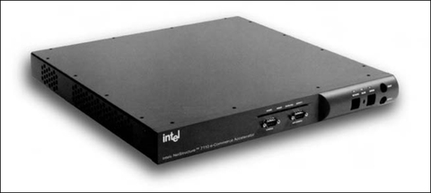
The Intel NetStructure 7110 e-Commerce Accelerator (www.intel.com/network/idc/products/accel_7110.htm) is a Secure Socket Layer (SSL) cryptographic accelerator that offloads cryptographic functions from a primary Web server to increase performance on commerce-related Web sites. The unit is placed between the router and Web server, and can handle up to 200 secure connections per second. The NetStructure 7110 uses a serial-port based management console on the front of the unit and can be compromised via this interface to allow an attacker full access to the system internals.
The goal of this example is to attempt to gain administrator or user access to the device without having legitimate credentials. By physically opening up the device, examining the operating system stored on a simple memory card, and using software reverse-engineering techniques to analyze various portions of code, it was discovered that certain revisions of the NetStructure 7110 have an undocumented supervisor password, which overrides any administrator settings and allows full access to the internal components and file system. This example is based on Brian Oblivion’s NetStructure 7110 Console Backdoor advisory (www.atstake.com/research/advisories/2000/ipivot7110.html) and was researched on a unit manufactured in April 2000.
Opening the Device
The NetStructure 7110 device is housed in a standard 19” rack-mount case and closed with non-descript screws (Figure 14.13). Opening the unit reveals a standard PC motherboard and Pentium II 333MHz processor. A Rainbow CryptoSwift Accelerator card (www.rainbow.com/cryptoswift/PCI.html) is attached on the local PCI bus of the motherboard and handles the actual encryption and decryption functionality of the NetStructure. There is no hard drive, as the filesystem is located on a Flash ROM-based CompactFlash (www.compactflash.org) memory card. There are no apparent tamper mechanisms, other than a small seal on the exterior of the housing, which was carefully removed before opening (and replaced when the experiments were complete).
Retrieving the Filesystem
The fact that the entire filesystem is stored on a 32MB CompactFlash card simplifies our attack. Due to the small size of the Flash ROM (compared to hard drive sizes of 20GB and larger for typical servers), duplicating it is easy. Our goal for this part of the hack is to successfully duplicate the filesystem, search the binary image for any interesting information, and attempt to mount the disk for further analysis.
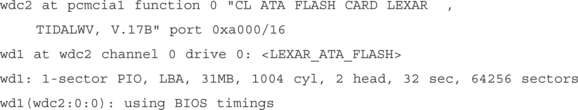
First, we remove the CompactFlash card from the NetStructure device and insert it into a PCMCIA CompactFlash adapter, which can be plugged into a laptop or desktop machine (Figure 14.14).

CompactFlash cards are compatible with the ATA/IDE hard drive specification, so most operating systems will automatically detect the cards without the need for additional drivers. The card was automatically detected by a laptop running OpenBSD 3.0:
At this point, we use dd to create an exact image of the CompactFlash card. We specify /dev/wda1 as the input file (which is the CompactFlash card); fs.bin as the output file, and the block size to 1 byte (the smallest possible):
# dd if=/dev/wd1a of=fs.bin bs=1
30081024 bytes transferred in 379.838 secs (79194 bytes/sec)
The fs.bin file is now an exact image of the NetStructure 7110 CompactFlash card. At this point, we can use strings to extract any ASCII-printable characters and look for any interesting text components stored on the card:
Looking through the text file output of strings (fs.strings in this example), we notice some network configuration commands (ifconfig, route add) and some hard-coded IP addresses. Of most importance is the following string, which immediately identifies the data on the CompactFlash card as being a filesystem from a BSD flavor of UNIX:
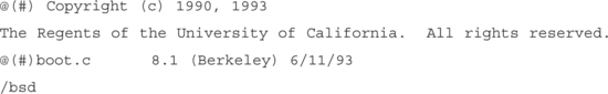
Knowing that the memory card contains BSD, we can attempt to ‘mount’ the card to the /mnt/fs directory (as read-only to prevent us from accidentally overwriting data on the original card), which should allow us access to the filesystem.
# mount −r −a /dev/wd1a /mnt/fs
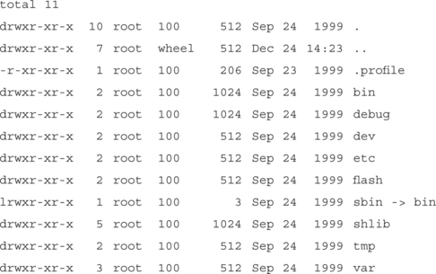
Once successful, an ls -la /mnt/fs outputs the following:

The card contains a compressed filesystem as shown by bsd.gz and filesys.gz. Using gunzip to uncompress the files, we can then prepare the image to be mounted in the following fashion:
# vnconfig −cv /dev/vnd0c filesys
Using vnconfig will prepare to use an image file as a filesystem, allowing it to be accessed as though it were a disk. A disklabel vnd0 outputs the following:

Finally, we will mount the raw device (/dev/vnd0c, created by vnconfig):
# mount −r −a /dev/vnd0c /mnt/filesys
Once successful, an ls –la /mnt/filesys outputs the following:
Finally, this directory structure appears to be a standard structure for a filesystem. After the successful mount, we are now able to access the complete filesystem (which was compressed and stored on the CompactFlash card) and traverse the directory structure and read files at will.
Reverse-engineering the Password Generator
While examining the contents of the filesystem created from the filesys.gz image, it was noted that a number of applications existed on the CompactFlash that should have been removed from a production unit: such applications included gdb and tcpdump, which were both found in the /debug directory. The /bin directory contained xmodem, which could be used to upload additional tools to the device; and a number of diagnostic applications (cr_diag for the Rainbow CryptoSwift Accelerator card, ser_diag for the serial port, exp_diag for the network interface card, and lm_diag for system timing).
Other applications specific to the Intel NetStructure 7110 device exist, such as saint, ipfwasm, ipfwcmp, gen_def_key, and gp. The strings output of gp reveals a usage string that takes in an Ethernet MAC address or interface. This seems interesting and warrants further investigation.
Usage: gp [aa:bb:cc:dd:ee:ff | ifname]
Using rec, a reverse–engineering compiler (www.backerstreet.com/rec/rec.htm), it was determined that the gp application will take in a MAC address and convert it to the default supervisor password. Furthermore, gp was compiled with all debug symbols enabled, making the reverse–engineering process much easier.
The supervisor password of each NetStructure device is derived from the MAC address of the primary NIC installed in the unit. During the device’s boot process and before every login, the MAC address is presented to the user on the serial console port. The password can be entered from the management console (via the serial port) if the attacker has physical access to the machine, or remotely if a modem has been connected to the NetStructure and configured for remote access. The password will override any administrator settings and allow full access into the device. A proof–of–concept tool with source code is available (www.atstake.com/research/tools/ipivot.tar.gz) to demonstrate the MAC address–to–password encoding.
Summary
In this chapter, we introduced and discussed hardware hacking. The hardware hacking process is broken down into two areas: mechanical and housing ttacks, which look at the physical housing and tamper mechanisms of the device, and electrical circuit attacks, which focus on reverse–engineering and attacking the internal circuitry. Depending on your goals, what you choose to attack, and how you elect to do it will vary. Often, hardware hacking is done to gain a security advantage (such as retrieving secret data components or elevating privilege) or change a product’s functionality.
In the “Opening the Device: Housing and Mechanical Attacks” section, we examined a number of concepts related to tamper mechanisms; including tamper resistance, tamper evidence, tamper detection, and tamper response; all of which are commonly used to prevent access to components and data. We looked at reasons and methods to open product housings, identifying external interfaces, and analyzing any data transfer protocols used, since these ports are often used for retrieving information (such as passwords or data sent in the clear) or for product configuration purposes. EMI/RF interference and ESD susceptibility were also examined, due to the fact all electronic devices generate EMI, and it can be used for passive monitoring attacks.
In the “Analyzing the Product Internals: Electrical Circuit Attacks” section, we examined a number of concepts related to reverse–engineering of the product circuitry and looked at a number of attack techniques. This section is arguably the “meat” of hardware hacking. Creating a schematic based on the printed circuit board is crucial to help discover any design flaws and identify attack vectors. The most basic attacks are related to data extraction from microprocessors or external memory components (to retrieve stored passwords or other information). Operating the device outside of its intended environment (such as by varying voltage, temperature, or clock timing) sometimes produces unintended results that are beneficial to an attacker. The advanced techniques we examined included removing epoxy encapsulation (which is used to prevent device probing and tampering), and IC delidding and silicon die analysis (which can be used to extract program code, state machine functionality, or cryptographic components).
The “What Tools Do I Need?” section presented a starter kit and an advanced kit required for hardware hacking. The cache of tools needed in a hardware hacker’s arsenal are very different than those needed for software or network–related hacking. In most cases, hardware hacking can be successfully executed with a minimal set of tools and a small investment of time, money, and determination.
The two examples shown (one for the Dallas Semiconductor DS1991 iButton Authentication Token and the other for the Intel NetStructure 7110 e–Commerce Cryptographic Accelerator) show that any product, large or small, can be attacked. The iButton was designed into a tamper–resistant metal housing while the NetStructure was easily opened with a standard screwdriver. The internal components of the two products varied widely. Regardless, the results were the same: The security mechanisms of both products could be compromised and used to an attacker’s advantage.
Hardware hacking is an up–and–coming area within the security space. Although yet to reach the popularity of network or software hacking, security–related hardware devices are becoming commonplace in corporate infrastructure, leaving the door wide open to new worlds of experimentation.
Solutions Fast Track
Understanding Hardware Hacking
![]() Generally, the goal of hardware hacking is to gain a security advantage or make a product do something it wasn’t originally intended to do.
Generally, the goal of hardware hacking is to gain a security advantage or make a product do something it wasn’t originally intended to do.
![]() Housing and mechanical attacks target the physical housing of the device with the goal of understanding the product manufacturing process and gaining access to the internal circuitry.
Housing and mechanical attacks target the physical housing of the device with the goal of understanding the product manufacturing process and gaining access to the internal circuitry.
![]() Electrical circuit attacks target the product circuitry and other internal components in order to determine and exploit security weaknesses.
Electrical circuit attacks target the product circuitry and other internal components in order to determine and exploit security weaknesses.
Opening the Device: Housing and Mechanical Attacks
![]() The main goal is to understand how the product was put together and to get access to the device internals and circuitry in order to further the electrical circuit attacks.
The main goal is to understand how the product was put together and to get access to the device internals and circuitry in order to further the electrical circuit attacks.
![]() Tamper mechanisms (including tamper resistance, tamper evidence, tamper detection, and tamper response) are commonly used to prevent access to components and data.
Tamper mechanisms (including tamper resistance, tamper evidence, tamper detection, and tamper response) are commonly used to prevent access to components and data.
![]() External interfaces to the outside world and any protocols the device may use for data transmission are examined. Electromagnetic and radio-frequency (EMI/RF) interference and electrostatic discharge (ESD) susceptibility are also of interest.
External interfaces to the outside world and any protocols the device may use for data transmission are examined. Electromagnetic and radio-frequency (EMI/RF) interference and electrostatic discharge (ESD) susceptibility are also of interest.
Analyzing the Product Internals: Electrical Circuit Attacks
![]() Electrical attacks often require invasive physical access to the device circuitry.
Electrical attacks often require invasive physical access to the device circuitry.
![]() A schematic (or electronic road map) of the circuitry is reverse-engineered from the printed circuit board. This serves as a base to determine any design flaws and identify any possible attack vectors.
A schematic (or electronic road map) of the circuitry is reverse-engineered from the printed circuit board. This serves as a base to determine any design flaws and identify any possible attack vectors.
![]() Basic attack techniques include analyzing physical memory, device probing, and timing attacks.
Basic attack techniques include analyzing physical memory, device probing, and timing attacks.
![]() More advanced techniques include removing epoxy encapsulation, IC delidding, and analyzing the silicon die.
More advanced techniques include removing epoxy encapsulation, IC delidding, and analyzing the silicon die.
What Tools Do I Need?
![]() The toolset required for hardware hacking is extremely different than that needed for network or software hacking.
The toolset required for hardware hacking is extremely different than that needed for network or software hacking.
![]() It is not necessary to have a world-class laboratory to conduct most hardware hacking. The majority of hardware hacking can succeed with a minimal set of tools.
It is not necessary to have a world-class laboratory to conduct most hardware hacking. The majority of hardware hacking can succeed with a minimal set of tools.
![]() Advanced analysis and hardware hacking sometimes requires expensive tools and resources, many of which are available in academic laboratory environments.
Advanced analysis and hardware hacking sometimes requires expensive tools and resources, many of which are available in academic laboratory environments.
Example: Hacking the iButton Authentication Token
![]() The DS1991 MultiKey iButton makes use of three distinct passwords to protect three secure data areas. Only the correct password will grant access to the data stored within each subkey area.
The DS1991 MultiKey iButton makes use of three distinct passwords to protect three secure data areas. Only the correct password will grant access to the data stored within each subkey area.
![]() Dallas Semiconductor literature states that “false passwords written to the DS1991 will automatically invoke a random number generator that replies with false responses.”
Dallas Semiconductor literature states that “false passwords written to the DS1991 will automatically invoke a random number generator that replies with false responses.”
![]() The serial port (connecting the iButton reader to the host PC) was monitored to determine what type of data was being sent to and from the iButton.
The serial port (connecting the iButton reader to the host PC) was monitored to determine what type of data was being sent to and from the iButton.
![]() Experimentation and cryptanalysis led to the discovery that the response returned by iButton device on an incorrect password entry is not random, but is based solely on the password entered. This “incorrect password” response can be pre–computed and compared to the actual response of the iButton under attack, which can lead to dictionary attacks against the device to determine the correct password.
Experimentation and cryptanalysis led to the discovery that the response returned by iButton device on an incorrect password entry is not random, but is based solely on the password entered. This “incorrect password” response can be pre–computed and compared to the actual response of the iButton under attack, which can lead to dictionary attacks against the device to determine the correct password.
Example: Hacking the NetStructure 7110 E-commerce Accelerator
![]() The Intel NetStructure 7110 is an SSL cryptographic accelerator used to offload cryptographic functions from a primary Web server to increase performance on commerce–related Web sites.
The Intel NetStructure 7110 is an SSL cryptographic accelerator used to offload cryptographic functions from a primary Web server to increase performance on commerce–related Web sites.
![]() Inside the unit reveals a standard PC motherboard and peripherals. There is no hard drive. A Flash ROM-based CompactFlash memory card is used in place of a hard drive.
Inside the unit reveals a standard PC motherboard and peripherals. There is no hard drive. A Flash ROM-based CompactFlash memory card is used in place of a hard drive.
![]() The unprotected CompactFlash was removed from the system and mounted onto a laptop for imaging and analysis. The resulting filesystem, a BSD variety, was compressed and stored on the CompactFlash and contained a number of applications not suitable for production release.
The unprotected CompactFlash was removed from the system and mounted onto a laptop for imaging and analysis. The resulting filesystem, a BSD variety, was compressed and stored on the CompactFlash and contained a number of applications not suitable for production release.
![]() Reverse-engineering the gp application stored on the CompactFlash showed how to generate a supervisor password (based on the MAC address of the device’s primary NIC), which can override any administrator settings and allow full access into the NetStructure 7110.
Reverse-engineering the gp application stored on the CompactFlash showed how to generate a supervisor password (based on the MAC address of the device’s primary NIC), which can override any administrator settings and allow full access into the NetStructure 7110.
Frequently Asked Questions
The following Frequently Asked Questions, answered by the authors of this book, are designed to both measure your understanding of the concepts presented in this chapter and to assist you with real–life implementation of these concepts. To have your questions about this chapter answered by the author, browse to www.syngress.com/solutions and click on the “Ask the Author” form.
A: Experimenting with and hacking hardware is important for a number of reasons. First, hardware hacking is not as prevalent as network or software hacking. Because of this, the doors are wide open for the discovery of hardware–related security problems. With just about any hardware security product, there is the likelihood of finding a problem or class of problems. Second, software cannot exist without hardware. Hardware is like the foundation of your house, which needs to exist before things are built on top of it. If the foundation is weak, it doesn’t matter how strong the application is on top of it. This is especially of concern if there is security software (encryption, authentication, or other data protection) running on top of insecure, unprotected hardware (which could be hacked using the methods described in this chapter). Third, many emergent technologies are based on both hardware and software (e.g., network appliances, wireless, smart cards). Hardware hacking serves as an important piece of the larger puzzle.
Q: How did hardware hacking begin?
A: There is no single point in time for the origins of hardware hacking, though it arguably dates back almost 200 years. Charles Babbage’s Difference Engine of the early 1800s was a mechanical form of hardware hacking. Possibly the first form of electronics–related hardware hacking was William Crookes’ discovery of the electron in the mid–1800s. Throughout the development of wireless telegraphy, vacuum tubes, radio, television, and transistors, there have been hardware hackers. Benjamin Franklin, Thomas Edison, and Alexander Graham Bell were hardware hackers. As the newest computers of the time were developed (ENIAC, UNIVAC, and IBM mainframes), people from those academic institutions fortunate enough to have the hardware came out in droves to experiment. With the development and release of the first microprocessor (Intel 4004) in November 1971, the general public finally got a taste of computing. The potential for hardware hacking, especially in the computer security realm, has grown tremendously in the past decade, as computers and technology become more intertwined with the mainstream and everyday living.
Q: What is the best way to learn about basic electronics theory?
A: Aside from formal schooling or classes at a local university (many of which offer electrical engineering courses), there are a number of excellent books and magazines to help you learn about electronics. The Art of Electronics (Cambridge University Press, 1989) by Horowitz and Hill is essential reading for basic electronics theory and covers just about every aspect. It is often used as a course textbook in university programs. For a detailed view into digital logic, Digital Design (Prentice–Hall, 1995) by Mano presents “digital logic design techniques, binary systems, Boolean algebra and logic gates, simplification of Boolean functions, and digital computer system design methods.” Radio Shack offers the “Engineer’s Notebook” series of books that provide an introduction to formulas, tables, basic circuits, schematic symbols, integrated circuits, and optoelectronics (light emitting diodes and light sensors). Three of the more popular hobbyist magazines, Nuts & Volts (www.nutsvolts.com), Circuit Cellar (www.circellar.com), and Poptronics Magazine (www.gernsback.com), are produced monthly and contain a good amount of information and do–it–yourself projects.
Q: Are there mailing lists, newsgroups, and Web sites within the hardware hacking community?
A: Although there are many Web sites and resources for electronics and hardware hacking in general, the community for hacking security–based hardware products is loose–knit and rather obscure. Usenet newsgroups, such as sci.electronics.design, comp.arch.embedded, and comp.security.misc discuss hardware hacking in small quantities. The “Coderpunks” mailing list archive, intended for discussion on cryptosystem analysis and implementation (www.privacy.nb.ca/cryptography/archives/coderpunks/charter.html) contains interesting hardware–related discussions, including such topics as smartcards, keystroke logging detection, and implementing cryptographic algorithms in hardware. The Gnet project (www.guerrilla.net) aims to create an alternative wireless network free from government and commercial obstruction and is one of the few groups hacking hardware on a regular basis. Their Web site features a number of hardware modifications for 802.11 wireless Access Points, NICs, and antennas.
Q: Would it be useful to learn about embedded systems? How exactly do they relate to hardware hacking?
A: Many of today’s security and hardware products consist of an embedded system, which is an electronics system run by a microprocessor/controller designed to perform a dedicated function. In embedded systems, there is a union of hardware (the underlying circuitry) and software/firmware (code that is executed on the processor). You cannot have one without the other. Thousands of various microprocessors exist and the device chosen for a particular product often depends on speed, width (for example, 8–, 16–, or 32–bit), and on–chip peripherals (including RAM/ROM, LCD control, IrDA support, PCMCIA interface, RF capabilities, security features), as well as the common variables such as cost, size, package type, and availability.
Having an understanding of the various microprocessor families and the associated low–level assembly language is extremely useful for reverse engineering hardware. Common microprocessors include the Motorola 6800– and 68000–families (such as the DragonBall MC68328 currently used in Palm devices), Zilog Z–80, Intel StrongARM, i960–, 8051– and x86–families, and Microchip PIC (used in many varieties of the Microsoft mouse). Many other vendors and processor types exist, each with different configurations and embedded functionality. Randall Hyde’s “The Art of Assembly Language” documents (http://webster.cs.ucr.edu/index.html) are a great reference for Intel x86–based assembly language and serve as a resource for all facets of low–level programming. Microprocessor product data sheets and developer documentation contain instruction sets, register maps, and other information specific to the selected device. Once the concept of assembly language and low–level microprocessor operation is understood, it can be applied to any family of microprocessor device with only minor changes.