Ioan D. Marinescu† * The University of Toledo, Toledo, Ohio † MIME Dept., University of Toledo, Toledo, Ohio
Abstract
This chapter introduces and reviews abrasive processes assisted by ELectrolytic In-process Dressing (ELID) technique. This in situ dressing method is used for metal-bond wheels and is relatively new. As illustrated by the examples given below, the introduction of this technique has been highly successful when fine grain wheels were efficiently used to obtain very low surface roughness, and when hard ceramics had to be machined using a very small grain cutting depth in order to avoid failure by cracking.
The basic system, principles, and characteristics of ELID abrasion mechanisms are introduced first. The success and wide application of ELID principles to ceramic grinding is explained. Fourteen applications of the ELID principle to modern abrasive processes are documented to illustrate the scope of application.
Keywords
ELID grinding
dressing technique
ELID principle
ELID application
7.1. Introduction
This chapter introduces and reviews abrasive processes assisted by electrolytic in-process dressing (ELID) technique. This in situ dressing method is used for metal-bond wheels and is relatively new. As illustrated by the following examples, the introduction of this technique has been highly successful when fine grain wheels were efficiently used to obtain low surface roughness, and when hard ceramics had to be machined using a small grain cutting depth in order to avoid failure by cracking.
The basic system, principles, and characteristics of ELID abrasion mechanisms are introduced first. The success and wide application of ELID principles to ceramic grinding are explained. Fourteen applications of the ELID principle to modern abrasive processes are documented to illustrate the scope of application.
7.2. Basic system
ELID grinding was first proposed by the Japanese researcher Hitoshi Ohmori back in 1990 [1]. The most important feature is that no special machine is required. Power sources from conventional electrodischarge or electrochemical machines can be used for ELID, as well as ordinary grinding machines.
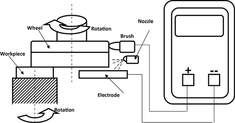
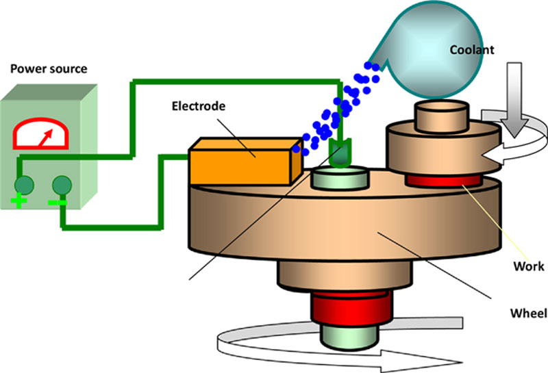
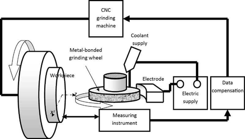
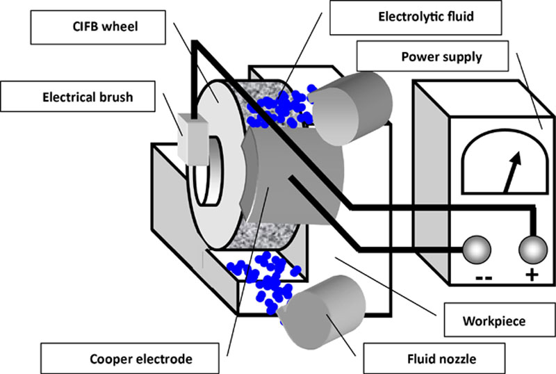
The basic arrangement of the ELID system for surface grinding is shown in Figure 7.1. The essential elements of the ELID system are a metal-bonded grinding wheel, a power source, and a high pH electrolytic coolant. The metal-bonded wheel is connected to the positive terminal of a power supply with a smooth brush contact, while the fixed electrode is connected to the negative pole. The electrode is made out of copper and must cover at least one-sixth of the wheel’s active surface with a width that is 2 mm wider than the wheel rim thickness. The gap between the wheel and the active surface of the electrode is 0.1–0.3 mm and can be adjusted by mechanical means.
Figure 7.1Basic arrangement for ELID grinding
The grinding wheel is dressed as a consequence of the electrolysis phenomenon that occurs between the wheel and the electrode when direct current (DC) is passed through a suitable grinding fluid that acts as electrolyte.
7.3. Basic principles
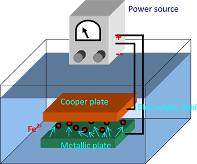
ELID grinding is a process that employs metal-bonded superabrasive wheel together with in-process dressing by means of an electrolytic action. The basic principle of the electrolysis is illustrated in Figure 7.2. The electrolytic process continuously exposes new sharp abrasive grains by dissolving the metallic bond around the superabrasive grains in order to maintain a high material removal rate and to obtain a constant surface roughness.
Figure 7.2The principle of electrolysis
A key issue in ELID, according to Chen and Li is to balance the rate of removal of the metal bond by electrolysis and the rate of wear of the superabrasive particles [2]. Although the superabrasive wear rate is directly related to grinding force, grinding conditions, and workpiece mechanical properties, the removal rate of the metal bond depends on ELID parameters such as voltage, current, and the gap between the electrodes.
The rate of dissolution of the bond metal is highest at the metal-diamond interface particles. In other words: the tendency of electrolytic dissolution is to expose the diamond particles [2]. Consequently, the metal dissolution rate increases with concentration of the diamond particles [2].
Figure 7.3 shows the basic mechanism of ELID dressing process, while Figure 7.4 presents the progression of the dressing during the grinding process, which materializes in the three stages: trueing, dressing and grinding/dressing.
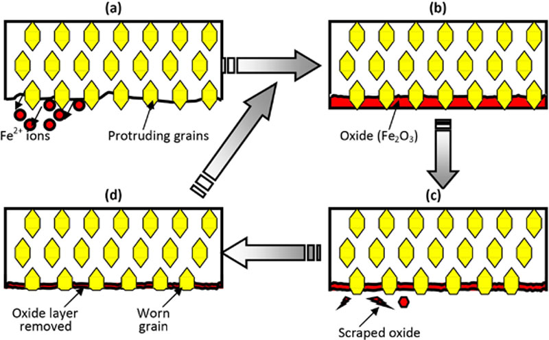
Figure 7.3Mechanism of ELID [27]: (a) Predressing started, (b) predressing completed, (c) dressing started, and (d) dressing stabilized
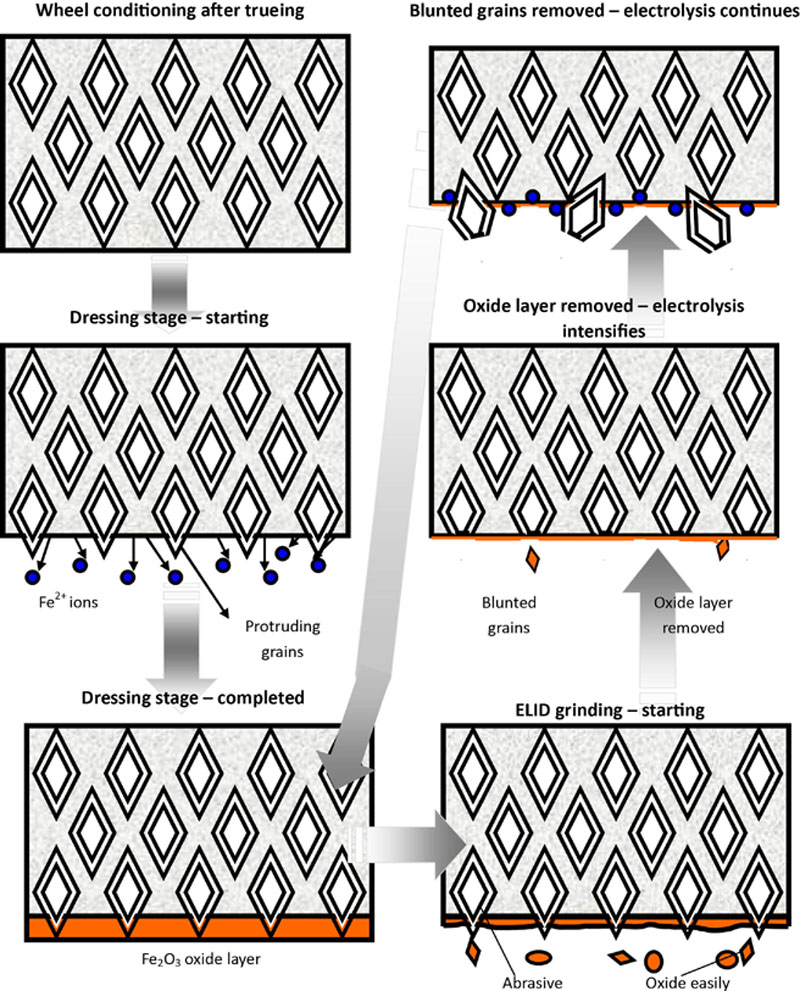
Figure 7.4Stages of ELID grinding
For a fixed gap and applied voltage, the current density does not change much with concentration of diamond particles [2]. Hence, in order to maintain a constant rate of metal removal, the applied electric field should be lower for a higher diamond concentration and, vice versa, the applied electric field should be higher for a lower concentration of particles. This electric field concentration effect is greatly reduced when the diamond particle is half exposed [3]. The field sharply decreases from its highest value, near the diamond-metal boundary, to a small value at a distance of the order of the diamond particle size [3].
In a conventional grinding operation, the tool face is smooth and has no protrusion of diamond particles after trueing [3]. Mechanical dressing opens up the tool face by abrasion with a dressing stone, which exposes the grits on the leading side while they remain supported on the trailing side. Laser and electrodischarge dressing opens up the tool face by thermal damage, producing craters, microcracks, and grooves. This thermal change degrades the diamonds because diamond undergoes a graphitization alteration at approximately 700°C. During electrochemical dressing operations, grits are exposed by dissolving the surrounding metal bonds [3].
The stages of ELID grinding are depicted in Figure 7.4:
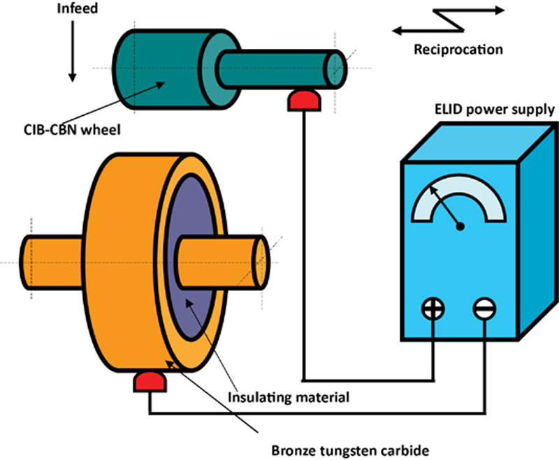
1. Trueing is carried out to reduce the initial eccentricity below the average grain size of the wheel and to improve wheel straightness, especially when a new wheel is first used or reinstalled. Precision trueing of a micrograin wheel is carried out to achieve a runout less than 2–4 μm. In Figure 7.5, details of the trueing method are presented. A special electrical discharge (ED) trueing wheel, made out of high-temperature bronze-tungsten carbide alloy and insulated from its central shaft, is mounted on three-jaw chuck and connected to negative pole. Both wheels rotate at rather low speed and the ED-trueing wheel reciprocates with the machine tool’s saddle. Little or no coolant is supplied to prevent electrolysis and to obtain high trueing precision. After trueing, a predressing operation is required prior to grinding.
2. Predressing of the wheel by electrolytic means is meant to increase protrusion of the abrasive grains. The procedure is performed at low speed and takes about 10–30 min.
3. Grinding is performed simultaneously with continuous in-process dressing by electrolytic means.
Due to the changes in the wheel surface condition, the electrolysis parameters change in the last two stages as shown in Figure 7.6 and explained in the next section.
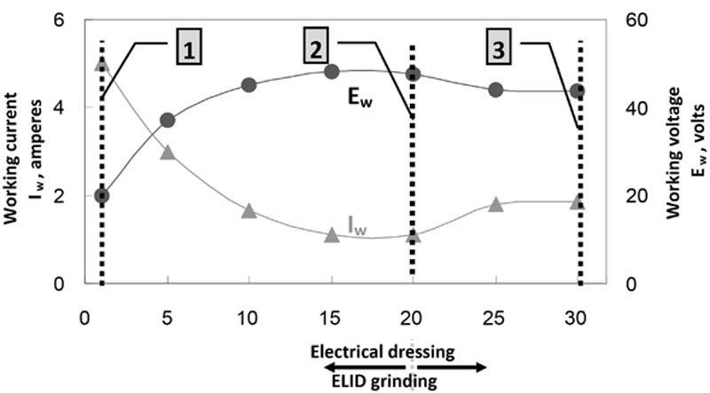
Figure 7.6Current characteristics during ELID grinding [6]
7.4. Electrical aspects of ELID grinding
The current Iw and voltage Ew vary during a complete ELID procedure. When the predressing stage starts, the active surface of the wheel has a high electrical conductivity. Consequently, the current is high, while the voltage between the wheel and the electrode is low, as indicated by vertical Line 1 in Figure 7.6. After several minutes, the cast iron bond material is removed by electrolysis, being transformed into Fe2+ ions. According to the chemical transformations shown in Figure 7.2, the ionized Fe forms hydroxides of Fe(OH)2 or Fe(OH)3. The hydroxides further change into oxides Fe2O3 through electrolysis. The electroconductivity of the wheel surface is reduced by the oxide that acts as an insulating layer (about 20 μm thick). The current decreases while the voltage increases as shown by the vertical Line 2 in Figure 7.6.
The grinding process can now commence with the protruding abrasive grains. As the grains are worn, the insulating oxide layer is also worn, which increases the electroconductivity of the wheel so the electrolysis will intensify and generate a fresh insulating layer depicted by the vertical Line 3 in Figure 7.6. The protrusion of the grains remains approximately constant. The layer of oxide has a larger flexibility and a lower retention characteristic than the bulk bond material [4].
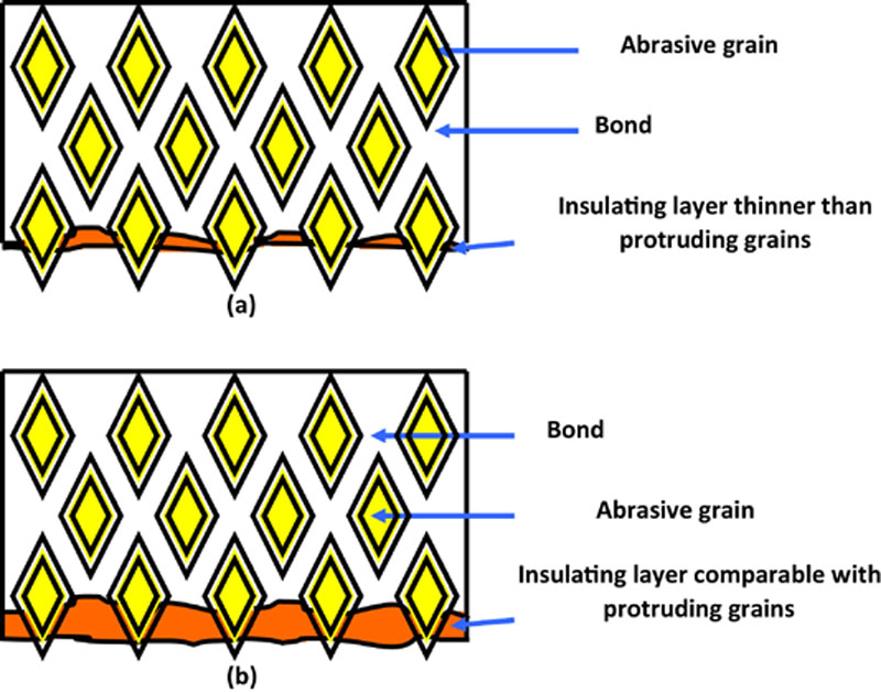
Figure 7.7 depicts the characteristics of the oxide film thickness required for different types of grinding operation: roughing or finishing. For rough grinding, a thin insulating layer is required so the abrasive grains can significantly protrude out of the bond and help increase the material removal rate, while for a mirror-finish ELID grinding a relatively thick insulating layer is preferred because it will limit the real depth of cut of the abrasive grains. The thickness of the oxide layer can be controlled by modifying the characteristics of the electrical current output by the ELID power source. This modification creates the possibility of running both rough and finish grinding operations using the same setup and adjusting only the current characteristics of ELID and relative speed between the wheel and the work.
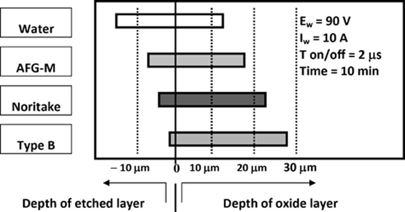
An important aspect during ELID dressing is a small increase of the wheel diameter (or thickness) that occurs during ELID grinding due to formation of the etched and oxide layers [4]. In Figure 7.8 typical increases in wheel diameter due to insulating layer formation are shown for different types of electrolyte.
Figure 7.8The depth of etched and oxide layers with different electrolytes [4]
7.5. Grinding wheels for ELID applications
Wheels for ELID applications include the following types:
Cast Iron–Bonded Diamond
These wheels are manufactured by mixing diamond abrasive, cast iron powder or fibers, and a small amount of carbonyl iron powder. The compound is shaped to the desired form under a pressure of 6–8 ton/cm2, and then sintered in an atmosphere of ammonia. These wheels are unsuitable for continuous grinding for long periods of time, particularly for metals for the following reasons:
1. A tough metal-bonded wheel is difficult to dress, so efficient and stable grinding cannot be achieved.
2. High material removal rate wears the abrasive and requires frequent redressing.
3. The wheel becomes embedded with swarf during grinding of steels and other metals.
Cast Iron Fiber–Bonded Diamond
These wheels provide high grinding ratio and high material removal rates.
Cubic Boron Nitride (CBN)
Tough metal-bonded CBN wheels can be dressed during the grinding process using the ELID technique. This process can be used to control abrasive protrusion before and during the grinding of ceramics.
7.6. ELID grinding of ceramics
In recent years, a number of publications confirm the merits of ELID grinding for common brittle materials, but also for BK-7 glass, silicon, and fused silica using fine-mesh superabrasive wheels [5]. Many of these publications report that ELID system provides the ability to obtain spectacularly fine finishes after grinding operations on brittle material surfaces, down to the nanometer scale of 4 to 6 nm. For some applications, this process completely eliminates the need for loose abrasive lapping and/or polishing operations. ELID grinding has also been applied to the fabrication of large optical components 150–250 mm in diameter. The data also suggest that ELID grinding can be successfully applied to thin deposited substrates.
According to the American Ceramic Society, the U.S. structural ceramics market was estimated at more than $3.5 billion as compared with $20 million in 1974, $350 million in 1990, and $865 million in 1995 (http://www.acers.org/news/factsheets.asp). Applications of ceramics are found in tool manufacture, automotive, aerospace, electrical and electronics industries, communications, fiber optics, and medicine.
The properties of ceramic materials, as for all materials, depend on the types of atoms, the types of bonding between the atoms, and the way the atoms are packed together, known also as the atomic scale structure. Most ceramics are compounded of two or more elements. The atoms in ceramic materials are held together by a chemical bond. The two most common chemical bonds for ceramic materials are covalent and ionic, which are much stronger than metallic chemical bonds. That is why, in general, metals are ductile and ceramics are brittle.
The atomic structure primarily affects the chemical, physical, thermal, electrical, magnetic, and optical properties. The microstructure also affects the properties but has its major effect on mechanical properties and on the rate of chemical reaction. For ceramics, the microstructure can be entirely glassy (glasses), entirely crystalline, or a combination of crystalline and glassy. In the last case, the glassy phase usually surrounds small crystals, bonding them together.
The most important characteristics of ceramic materials are high hardness, resistance to high compressive force, resistance to high temperature, brittleness, chemical inertness, electrical insulation properties, superior electrical properties, high magnetic permeability, special optic, and conductive properties.
The interest in advanced structural ceramics has increased significantly in recent years due to their unique physical characteristics and due to significant improvements in their mechanical properties and reliability. Despite these advantages, the use of structural ceramics in various applications has not increased as rapidly as one might have expected due, partly, to the high machining cost. The cost of grinding ceramics may account for up to 75% percent of the component cost compared to 5–15% percent for many metallic components [6].
The primary cost drivers in the grinding of ceramics are:
• Low efficiency machining operations due to the low removal rate
A conventional grinding process applied to ceramic materials often results in surface fracture damage, nullifying the benefits of advanced ceramic processing methods [7]. These defects are sensitive to grinding parameters and can significantly reduce the strength and reliability of the finished components. It is, therefore, important to reduce the depth of grain penetration to minimum values so that the grain force is below the critical level for structural damage. The critical value of grain penetration depth for a hard ceramic is typically less than 0.2 μm. This small value of grain penetration depth is made possible using the ELID grinding technique with fine grain wheels.
Although ELID grinding is good for workpiece accuracy, it is not necessarily beneficial to workpiece strength as the following discussion of the effects of removal rates demonstrates [8]. Stock removal rate increases with increasing number of passes, higher stock removal rates being obtained with a stiffer machine tool in the first few passes. For grinding wheels of a similar bond type, a larger stock removal rate is obtained for the wheels of larger grit sizes. Cast iron–bonded wheels used during the ELID grinding allow a larger stock removal rate, yet a lower grinding force than a vitrified bond grinding wheel used in a conventional grinding process. Machine stiffness has little effect on residual strength of ground silicon under multipass grinding conditions, which can be attributed to the effect of the actual wheel depth of cut on workpiece strength [9]. As the number of passes increases, the actual depth of cut approaches the set depth of cut, which means that regardless of machine tool stiffness, grinding force does not necessarily alter workpiece strength in a stable grinding process. Also, more compressive residual stress can be induced with a dull grinding wheel, with a grinding wheel of a larger grit size, or with a wheel with a stiff and strong bond material. However, a larger grinding-wheel grit size causes a greater depth of damage in the surface of the ground workpiece. As the number of passes increases, the normal grinding force also increases. This increase of force is steep initially and slows down as the number of passes increases, a phenomenon more evident for a high stiffness machine tool. Due to machine tool deflection, the normal grinding force is initially smaller with lower machine stiffness [9]. Eventually, the normal force approaches a limit value, regardless of the machine stiffness characteristics [9]. To avoid damage to the workpiece, it is necessary to limit the grain penetration depth, which is more directly dependent on the removal rate than on the grinding force.
A controversial and little studied aspect of the ceramic grinding process is the pulverization phenomenon that takes place in the surface layer of a ceramic workpiece during grinding [10]. Surface pulverization makes ceramic grains in the surface much smaller than those in the bulk and gives the ground surface a smoother appearance.
7.7. Material removal mechanisms in grinding of ceramics and glasses
In general, two approaches in investigating abrasive-workpiece interactions in ceramics grinding [7]:
1.The indentation-fracture mechanics approach models abrasive-workpiece interactions by the idealized flaw system and deformation produced by an indenter.
2.The machining approach involves measurement of forces coupled with scanning electron microscope (SEM) and atomic force microscope (AFM) observation of surface topography and of grinding debris.
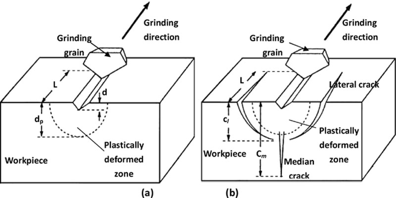
The stock removal during grinding of ceramics is a combination of microbrittle fracture and quasi-plastic cutting. The quasi-plastic cutting mechanism, typically referred to as ductile-mode grinding, depicted in Figure 7.8, results in grooves on the surface that are relatively smooth in appearance. Through careful choice of values for the grinding parameters and control of the process, ceramics can be ground predominantly in this so-called ductile mode. On the other hand, brittle-mode grinding shown in Figure 7.9 results in surface fracture and surface fragmentation. Ductile-mode grinding is preferred because negligible grinding flaws are introduced and structural strength is maintained.
Figure 7.9An abrasive grain depicted removing material from a brittle workpiece: (a) in ductile-mode grinding and (b) in brittle-mode grinding [7]
As shown in Figure 7.9, a plastically deformed zone is positioned directly under the grit. In brittle-mode grinding, two principal crack systems are generated: median (radial) cracks and lateral cracks. Brittle-mode removal of material is due to the formation and propagation of these lateral cracks.
The specific depth at which a brittle-ductile transition occurs is a function of the intrinsic material properties of plasticity and fracture. According to Bandyopadhyay, the critical depth is [7]:
PlasticFlowEnergyFractureEnergy≍EpEf≍d
(7.1)
where d is the critical depth of cut.
Although it is not always easy to observe microcracks produced by grinding, the depth of a median crack can be estimated using the following formula [11]:
lmc=[0.034(cotanψ)2/3{(E/H)1/2/Kc}]2/3F2/3
(7.2)
where ψ is the indenter angle, F is the indentation load, E is the modulus of elasticity, and Kc is the fracture toughness of the material. Therefore, the depth of the median crack depends on the material properties, force, and grinding grit shape.
Indentation load F is estimated by dividing the grinding force by the number of active cutting edges in the contact area between the grinding wheel and the workpiece. This relationship applies above a threshold force F*. The critical force F* that will initiate a crack can be estimated by:
F∗=α×K4cH3
(7.3)
where α is a coefficient that depends on the indenter geometry, and H is the hardness.
In conclusion, crack size can be estimated theoretically, from equation (7.2) when the force exceeds a certain critical value, determined by equation (7.3). Typical values of critical force to propagate subsurface damage are presented in Table 7.1[7]. In order to cut in the presence of plastic deformation, the grain load should be less than 0.2 N and 0.7 N for SiC and Si3N4, respectively, for a typical grain shape.
Table 7.1
Critical Force Required to Propagate Subsurface Damage [7]
Materials
H (GPa)
E (GPa)
Kc (kN/m3/2)
F* (N)
SiC
24.5
392
3400
0.2
Si3N4
14
294
3100
0.73
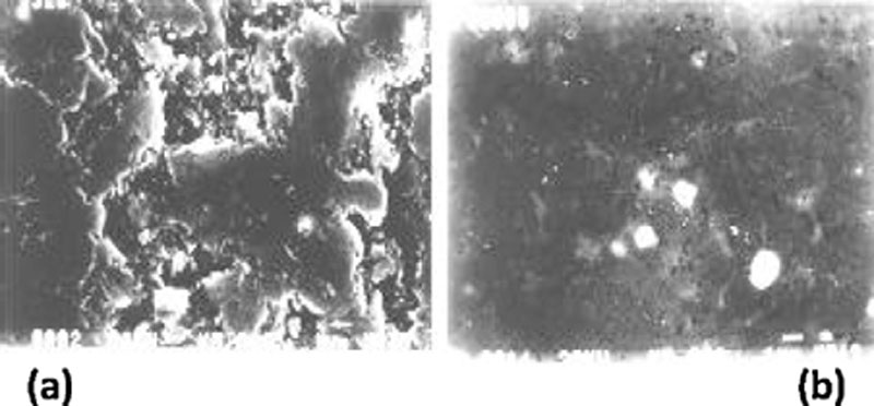
Scanning electron microscope (SEM) and atomic force microscope (AFM) techniques can be utilized to evaluate surface and subsurface fracture damage. Typical micrographs are shown in Figures 7.10 and 7.11. From SEM and AFM micrographs, one can assess the difference between brittle mode and ductile mode material removal.
Figure 7.10SEM micrographs [7]: (a) #325 and (b) #8000
Figure 7.11AFM micrographs [7]: (a) #325 and (b) #8000
7.8. Comparison between ELID and other grinding techniques
Significant reduction in grinding force has been reported with the application of ELID for workpieces ground both in the longitudinal and transverse directions.
ELID Grinding
Protruding grains abrade the workpiece. As a result, the grains and the oxide layer wear down. The wear of the oxide layer increases the electrical conductivity of the wheel. As a result, the electrical current in the circuit increases, leading to an intensification of the electrolysis. Consequently, protrusion of the abrasive grains increases and, during a short period, the thickness of the oxide layer recovers. The described electrical behavior is nonlinear, due to the formation of this insulating oxide layer. The oxide layer has a beneficial lubricating role in the grinding process. The process of wear and recovery of the oxide layer follows in a rather stable manner during the entire ELID grinding operation.
Other In-Process Dressing Technologies
Nakagawa and Suzuki investigated various techniques of in-process dressing[12]. The effects of in-process dressing using a dressing stick were studied. The wheel is dressed at the beginning of each stroke. Higher material removal rates were reported. An application of this procedure to side-grinding is difficult. However, use of a dressing stick accelerates wear of the superabrasive grains.
The technique of electrochemical dressing was introduced by McGeough in 1974 [13]. An electroconductive metal-bond wheel forms the anode and a fixed graphite stick forms the cathode. The dressing process takes place by electrolysis. Welch and others employed sodium chloride electrolyte [14]. However, sodium chloride is corrosive and is therefore harmful to the machine tool.
Another dressing technique is based on the principle of electrical discharge machining (EDM). The conductive grinding wheel is energized with a pulsed current. The flow of ions creates hydrogen bubbles in the coolant, creating an increasing electric potential. When the potential becomes critical, a spark is generated that melts and erodes the material that clogs the wheel. This procedure does not continuously provide protruding abrasive grains, being considered unsuitable for ultrafine grinding of materials, especially with micrograin-size grinding wheels.
Other nonconventional machining processes based on electrochemical metal removal include electrochemical machining, electrochemical grinding, and electrochemical polishing.
7.9. Applications of ELID grinding
ELID grinding has been investigated for various materials, including ceramics, hard steels, ceramic glass, and ceramic coatings, having a variety of shapes (plane, cylindrical external and internal, spherical and aspherical lens, etc.) and of greatly varying dimensions. Lately, new applications of ELID principle were tested for biomedical materials [15,16].
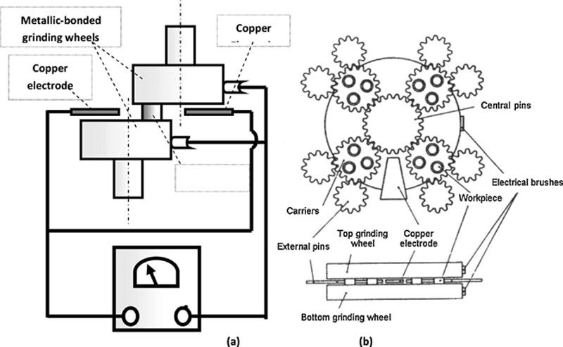
An ELID face-grinding setup is illustrated in Figure 7.12.
Figure 7.12Principle of ELID face grinding [4,9,22]
ELID grinding was found to offer advantages when compared to conventional grinding operations applied to the same workpieces under similar conditions. The oxide layer obtained during ELID grinding modifies the nature of the contact between the wheel and workpiece: it is, practically, equivalent to changing the wheel bond. The oxide layer makes the wheel surface more flexible compared to the hard and highly retentive cast iron bond in the conventional process. The conclusions of the study were the following:
• ELID grinding can be employed to produce mirror finishes.
• Surface roughness was slightly better.
• Fewer pits and sticking-out projections were produced on workpiece surfaces, ductile-mode removal being found to be dominant.
• ELID grinding was particularly recommended for precision grinding of hard-brittle materials on conventional machine tools with low rigidity.
ELID-lap grinding employs constant pressure and uses metal-bonded abrasive wheels with ELID. The process was found to produce better results from the surface roughness and flatness viewpoints than conventional lap grinding. ELID-lap grinding was found as a perfect candidate in the following scenarios:
• Achieve mirror finishes that cannot be obtained with constant feed grinding
• Grind with metal-bond wheels having grain-mesh size finer than JIS #10,000
• Employ a simple setup mounted on an existing lapping machine
Workpieces (silicon or tungsten carbide in this specific investigation) are pressed against the lapping wheel. The lapping wheel is connected to the positive pole through a fine brush that smoothly contacts the wheel surface, while the electrode is connected to the negative pole. The gap between the two electrodes is 0.3 mm.
Conclusions from the investigations include the following:
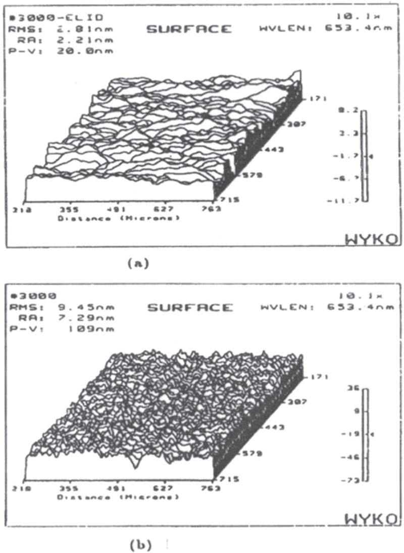
• ELID-lap grinding of silicon with JIS #4000 wheel was found to yield a mirror finish with a roughness of 3.8 nm, as compared to the 7.4 nm roughness obtained after conventional lap grinding.
• ELID-lap grinding of tungsten with JIS #4000 wheel allowed a more stable removal rate than conventional lap grinding over an 80-min period.
• ELID-lap grinding of silicon was achieved in brittle-mode for JIS #1200 and lower and in ductile-mode for JIS #4000 and finer mesh size.
• When silicon was ground together with tungsten carbide, surface roughness was lower compared to the surface finish obtained when silicon alone is ground alone; the brittle-to-ductile transition was observed for a JIS #4000 mesh size wheel.
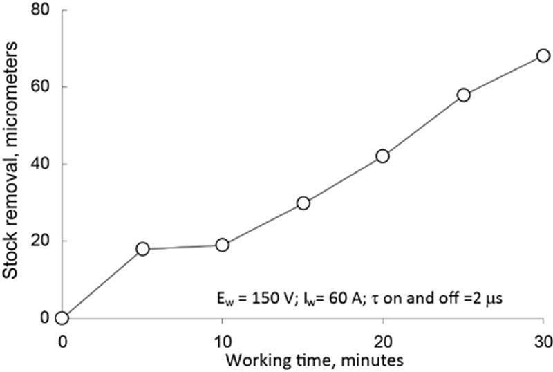
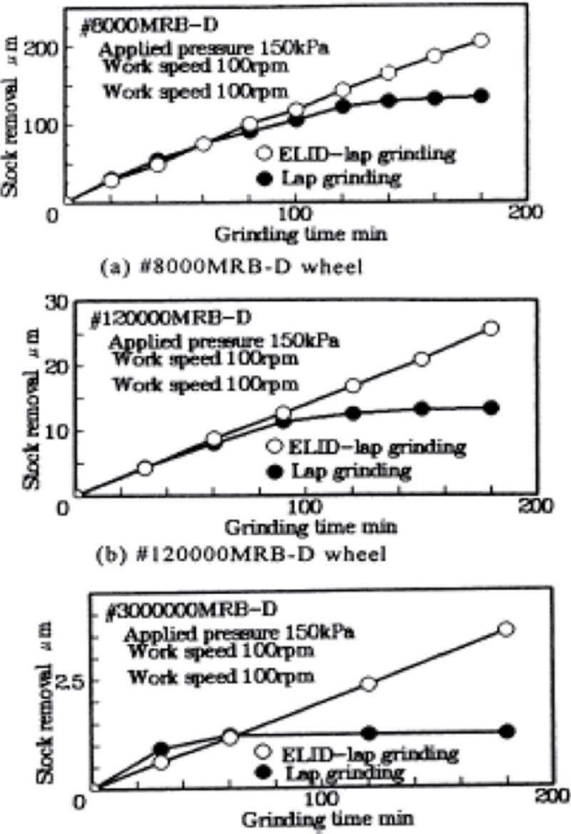
In a later study, silicon and glass (BK7) were ELID-lapped with metal-resin bond diamond wheels having grit sizes of JIS #8000, JIS #120,000, and JIS #3,000,000 [19]. Material removal rate results are presented in Figure 7.17.
Figure 7.17Grinding efficiency versus time for wheels of 8,000, 120,000, and 3,000,000 mesh size [19]
ELID-lap grinding using the JIS #3,000,000 metal-resin bond wheel produced high-quality ground surfaces of PV 2.8 nm for silicon and PV 2.5 nm for glass.
ELID Grinding of Ceramics on a Vertical Rotary Surface Grinder [6]
Experiments were conducted on a vertical rotary surface grinder having a 5.5 kW motor spindle. The workpieces were made from reaction-bonded silicon nitride (SRBSN) and cast-and-sintered silicon nitride (Si3N4). The grain size ranged between 0.3 and 0.4 μm (SRBSN) and 0.6 and 0.8 μm for Si3N4. Cast iron fiber–bonded diamond wheels of 200 mm in diameter were used. A Noritake AFG-M grinding fluid at a rate of 20–30 L/min was utilized as the electrolytic fluid.
The grain sizes for different JIS mesh sizes of diamond grinding wheels are presented in Table 7.2.
A direct-current pulse generator was utilized as a power supply. The square-wave voltage amplitude was 60 V with a peak current of 10 amps. The pulse width was adjusted to 5 μm on- and off-time.
The investigation led to the following conclusions:
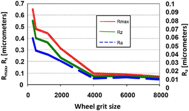
• Mirror finishes were obtained after grinding with a #4000 mesh size wheel, as shown in Figures 7.18 and 7.19.
Figure 7.18Effect of grit size on surface-roughness values [6]
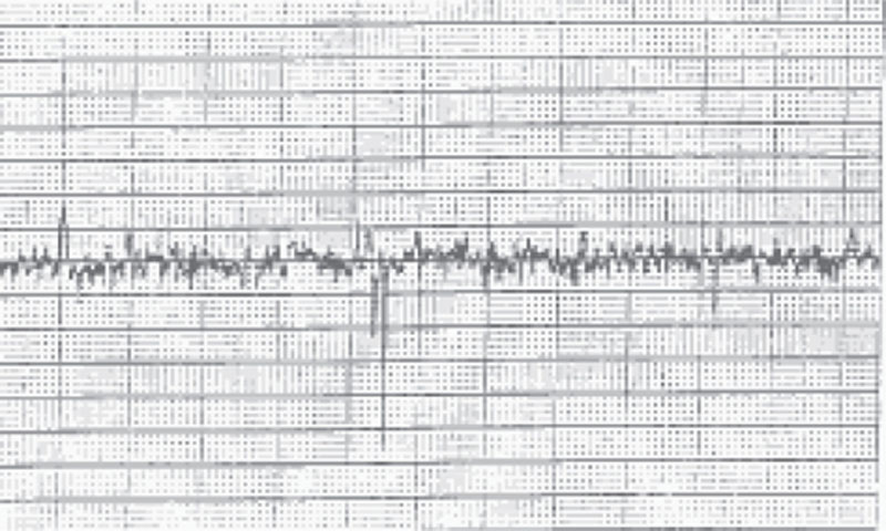
Figure 7.19Roughness of the surface (profile of the surface)
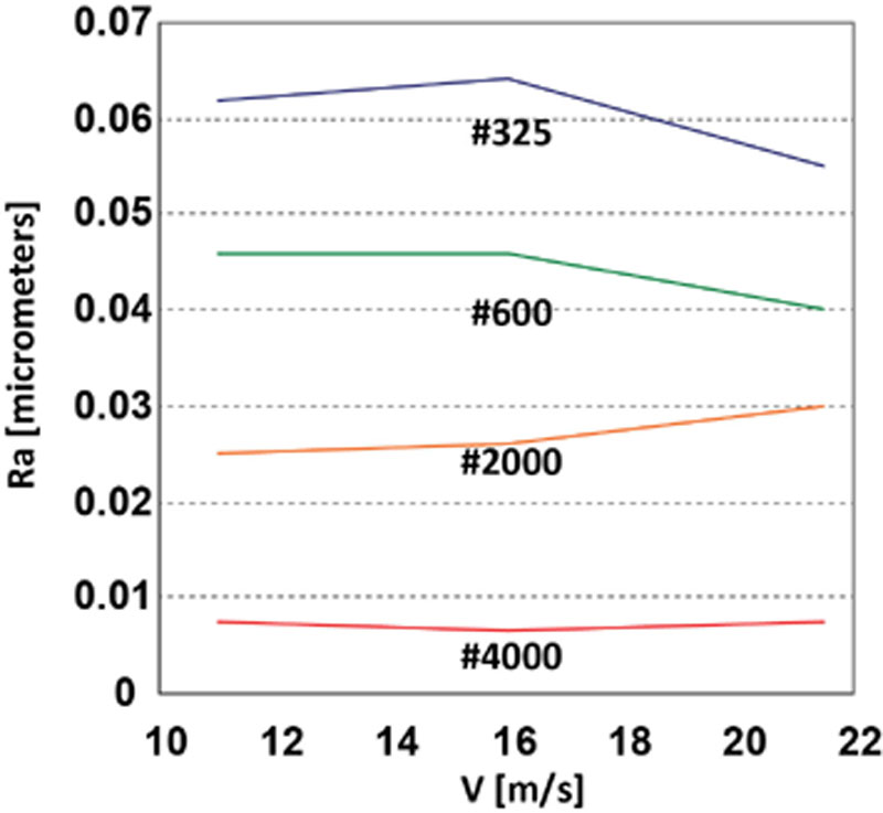
• Cutting speed had no significant effect on the surface roughness of the workpiece, as shown in Figure 7.20.
Figure 7.20Effect of cutting speed on surface roughness [6]
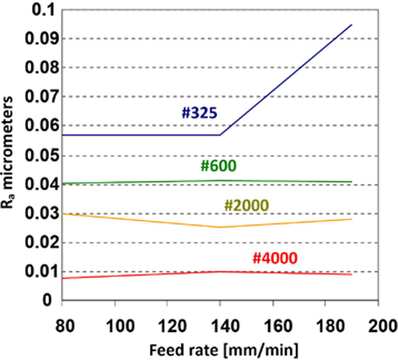
• Feed rate had no significant effect on the surface roughness, especially for mesh size wheels finer than JIS #325, as shown in Figure 7.21.
Figure 7.21Effect of feed rate on surface roughness [6]
• Lower surface roughness characterized SRBSN compared with Si3N4, especially with rougher wheels.
• Similar surface roughness characterized SRBSN and Si3N4 when finer wheels were used.
ELID Grinding of Ceramics on a Vertical Grinding Center [20]
The experiments were carried out on a vertical machining center. The silicon nitride workpieces were clamped firmly in a vise and fixed onto the base of a strain-gauge dynamometer. The dynamometer was clamped onto the machining center table, and a reciprocating grinding operation was performed.
A direct-current pulse generator was utilized as a power supply. The square-wave voltage was 60–90 V with a peak current of 16–24 amps. The pulse width was adjusted to 4 μm on-time and off-time. Different values between 0.01 and 0.05 mm for the depth of cut, and between 2 and 5 mm for the width of cut were explored. Material removal rates of 250 mm3/min and up to 8000 mm3/min were obtained. Results obtained after conventional grinding were compared with the results output by ELID grinding.
A modified ELID dressing procedure was also investigated. The modified ELID dressing was performed in two stages: (a) at 90 V for 30 min; the insulating oxide layer was mechanically removed by an aluminum oxide stick of #400 grit size at 300 rpm; (b) another dressing stage at 90 V for 30 min.
The investigation led to the following conclusions (see also Figure 7.22).
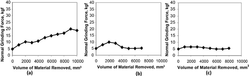
• ELID grinding favors high rates of material removal.
Figure 7.22Relationship between the volume of material removed and the grinding force for [20]: (a) conventional grinding; (b) ELID grinding after ELID dressing; and (c) ELID grinding after modified ELID dressing
• ELID grinding is recommended for low-rigidity machine tools and low-rigidity workpieces.
• Grinding force increased continuously during conventional grinding.
• Grinding force was less in ELID grinding than in conventional grinding; this effect became more visible after 18 min of grinding.
• Voltage increased with duration of ELID grinding, while the grinding force was reduced; this effect became apparent after 18 min of grinding.
• The full potential of ELID grinding was achieved after 24 min of grinding when the grinding force stabilized at a low value.
• ELID and conventional grinding produced almost the same surface roughness after rough grinding operation.
• The grinding force was constant and low after the application onto the wheel of the modified ELID dressing procedure.
ELID grinding was investigated as a super-finishing technique for steel bearing components. Cast iron-bond cubic boron nitride wheels (CIB-CBN) were used, the experiments being carried out on a common cylindrical grinder having a 3.7 kW motor spindle. The negative electrode was made from stainless steel. The electrolytic grinding fluid was Noritake AFG-M diluted 1:50 and supplied at a rate of 20–30 L/min. A direct-current pulse generator was employed. The square-wave voltage was 60–150 V with a peak current of 100 amps. Pulse width was adjusted to 4 μm on-time and off-time.
Three types of experiments were conducted:
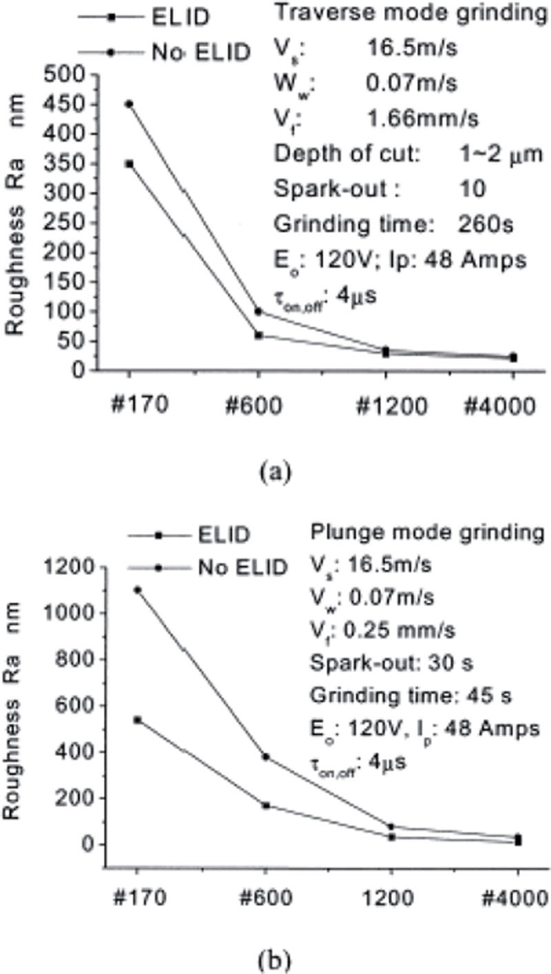
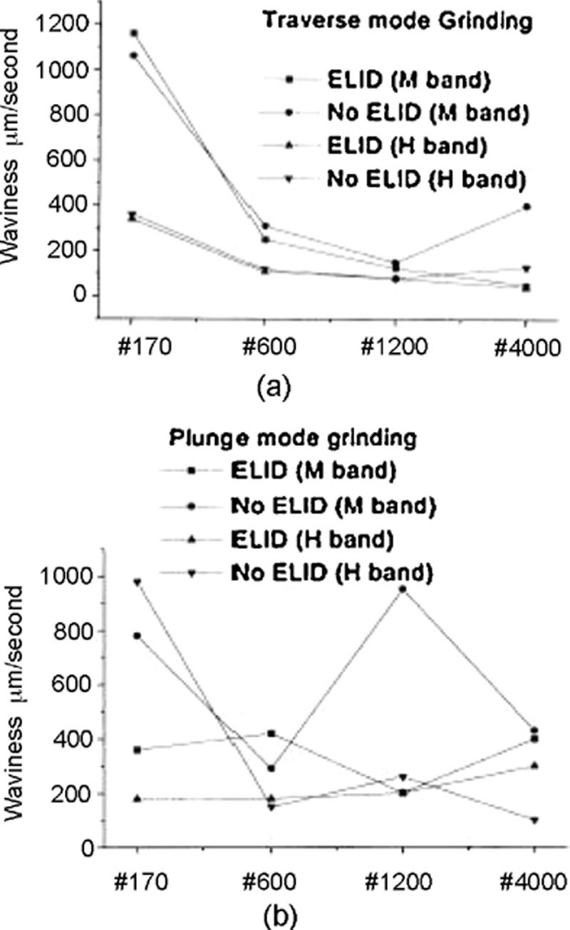
1. Traverse and plunge-mode ELID grinding experiments were completed in order to evaluate the effects of grinding wheel mesh size and grinding method on surface roughness and waviness (as shown in Figures 7.23 and 7.24).
Figure 7.23Comparison of roughness [21]: (a) traverse and (b) plunge
Figure 7.24Comparison of waviness [21]: (a) traverse and (b) plunge
2. Traverse grinding experiment, using different mesh size wheels, was conducted in order to assess the influence of wheel mesh size on surface finish and material removal rate.
3. ELID grinding with a #4000 mesh size wheel was carried out in order to compare the results with the results obtained after honing and electropolishing. During electropolishing, the workpiece is connected to the positive (or anodic) terminal, while the negative (cathodic) terminal is connected to a suitable conductor, with direct current applied (DC). Both positive and negative terminals are submerged in the solution, forming a complete electrical circuit.
The conclusions were as follows:
• ELID grinding offered a better surface finish (Ra = 0.02 μm for #4000 wheel) than conventional grinding.
• Plunge ELID grinding output was coarser surface roughness than traverse ELID grinding, especially for rougher abrasive wheels (see Figure 7.25).
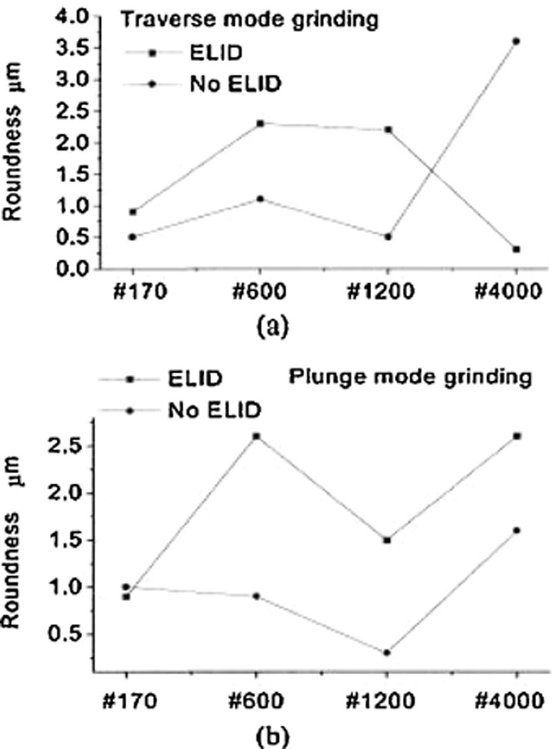
Figure 7.25Comparison of roundness [21]: (a) traverse and (b) plunge grinding
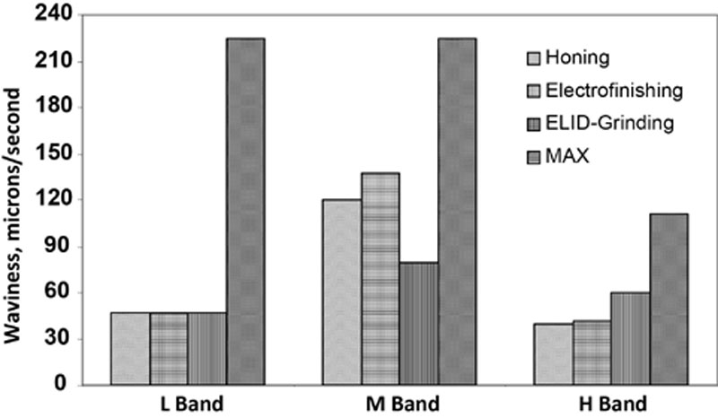
• Waviness of the ground surface was reduced for higher wheel mesh size (see Figure 7.26).
Figure 7.26Surface waviness with different processes [21]
• The ELID process was more stable for traverse grinding than for plunge grinding (see Figure 7.27).
• Roundness of the ground surface increased with wheel mesh number utilized.
• Out-of-roundness can be improved with greater stiffness of the machine tool.
• ELID traverse grinding tends to offer a more promising potential than plunge mode grinding.
• Three to four sparkout passes improved waviness and roundness of the ground surface.
• Effects of grinding parameters on surface roughness for ELID grinding and conventional grinding are comparable.
• Increased depth of cut and increased traverse rate produced a poorer surface roughness.
• ELID grinding gave better results than both honing and electric polishing.
• ELID ground surfaces have greater high band waviness than honed surfaces, due to the smaller workpiece-tool contact area.
• ELID grinding induced a lower compressive surface stress of about 150–400 MPa than the 600–800 MPa compressive stress resulting from honing.
• The 10 μm depth of the compressive layer produced by ELID operation was half as compared to the 15–20 μm depth produced by honing operation.
• The cycle time for ELID grinding was twice as long as the cycle time for either honing or electric polishing operation. However, lower roughness and higher removal rate were achieved by ELID grinding with a coarser wheel and for faster traverse speed. It was concluded that ELID grinding was more cost effective for small batch production situations.
Ceramic coatings include a large group of subspecies, such as chemical vapor–deposited silicon carbide, plasma spray–deposited aluminum oxide, and plasma spray–deposited chromium oxide. Efficient machining of these ceramic coatings in order to achieve the required quality is still under development. Zhang and colleagues made a comparative study of diamond grinding of ceramic coatings on a vertical grinder [22]. Two types of dressing procedures were applied to a cast iron–bond diamond wheel, having #4000 mesh size: alumina rotary dressing and ELID dressing and grinding.
Conclusions of the study were as follows:
• A critical current value for each electrolytic dressing system was found: when the current is smaller, the thickness of the insulating oxide layer increases with increase of current, otherwise it decreases.
• Thickness and depth of the oxide layer largely depends on the coolant type.
• A small increase in the wheel diameter and/or thickness occurred after electrolytic dressing. Conversely, during rotary and other mechanical methods of dressing, a reduction of the wheel diameter occurred.
• Workpiece roughness decreased more rapidly with rotary dressing than in ELID grinding in the first 3 min. After 3 min, roughness decreased constantly in ELID grinding but showed a wavelike model for rotary dressing.
• Wear of abrasive grains produced an unstable grinding performance for rotary dressing technique, while grinding performance remained constant during ELID grinding.
• Surface roughness depends on material properties in both methods.
• All ceramic coatings, except sintered SiC, had a lower roughness after ELID dressing than after rotary dressing.
• Plasma spray–deposited chromium oxide is difficult to grind to an extremely fine roughness.
• For all dressing methods, the micrographs showed that the material removal mechanism involved both brittle fracture and ductile mechanisms. For ELID dressing, the ductile mode was predominant, except for sintered SiC and for the rotary dressing, when the brittle fracture mode was predominant.
• Ductile mode grinding can be implemented even on a common grinder by controlling the wheel topography.
• For ELID grinding, the interaction between the abrasive grain and the workpiece surface is modeled by a spring-damper system (because of the existence of the oxide layer), while for rotary dressing the contact is rigid and stiff. The oxide layer absorbs vibrations and reduces the actual exposed cutting edge of the abrasive grain.
ELID Ultraprecision Grinding of Aspheric Mirrors [23]
The quality of soft X-ray silicon carbide mirrors influences the performance of modern optical systems. To accomplish a high precision of these aspheric mirrors an ELID grinding system was employed (see Figure 7.27).
A #1000 cast iron grinding wheel was mechanically trued and predressed using electrical methods. The workpiece surfaces were concave spherical with a curvature of 2 m. After grinding, the form was measured and the data were compared with the planned data by the mean least squares method. A form error was calculated and compensation data were generated. Accordingly, a new form was ground. This procedure was applied five times in order to exponentially decrease the errors from 2.6 to 0.38 μm.
The ELID grinding was investigated for production of microspherical lens in a ductile mode. The implementation of ductile-mode cutting requires expensive items such as ultraprecision vibration-free rigid machine tools, high-resolution feed-motion control, submicron grit wheels, and a clean work environment.
The conclusions reached were:
• ELID grinding is stable, efficient, and economical.
• Some problems in achieving ductile- or semiductile-mode grinding of micro-optical components occurred with low grinding speed, instability of ultrafine abrasive and small-size wheels, difficulty in achieving precise and efficient trueing and dressing of the wheels, and difficulty in obtaining precise and effective fixturing.
• Coarse grit size wheels (#325) do not show any difference in the final roughness when ELID is applied.
• Finer #4000 wheels, however, resulted in lower surface roughness when ELID was employed.
• ELID high-precision grinding of microspherical lens with cup wheels (ELID-CG grinding) achieved high spherical accuracy and low roughness around Ra 20 nm.
• ELID-CG grinding can be successfully utilized to fabricate microspherical lens with a more stable process, higher efficiency, and better surface quality than conventional grinding.
ELID Grinding of Large Optical Glass Substrates [5]
In this research, ELID grinding was employed to grind optical components 150–250 mm in diameter. ELID grinding using fine-mesh superabrasive wheels produced spectacularly low roughness of 4–6 nm Ra on brittle surfaces, including BK-7 glass, silicon, and fused silica. For some applications, ELID grinding eliminated polishing or lapping operations.
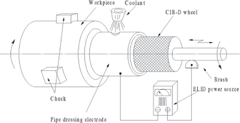
Little has been reported on mirror-finish internal grinding due to the limitation in abrasive grit size applicable to nonmetallic-bond grinding wheels. A novel method to carry out ELID grinding of internal cylindrical surfaces on an ordinary grinding tool, named interval ELID and presented in Figure 7.28, was developed. The wheel was dressed at intervals (before each stroke), and the abrasive grains remained protruding. After a predressing operation, the insulating oxide layer was 30 μm thick and increased the external diameter of the grinding wheel.
Figure 7.28Schematic of interval ELID grinding [25]
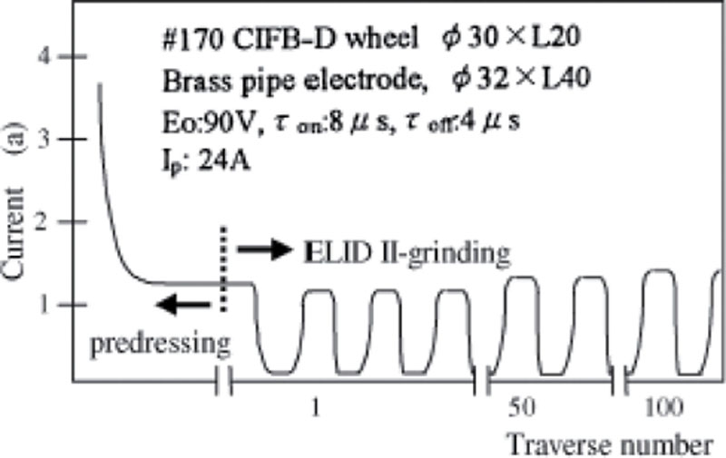
The characteristics of the electrical current utilized for interval ELID grinding are shown in Figure 7.29.
Figure 7.29Current fluctuation in interval ELID grinding [25]
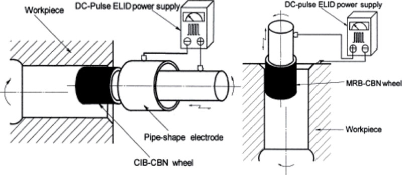
In internal grinding, abrasive wear occurs rapidly due to the smaller diameter of the wheel. These problems were overcome by interval ELID grinding technique. Two new techniques for internal grinding, namely ELID II and ELID III, are also described in the literature, Figure 7.30. For ELID II, a fixed cylindrical dressing electrode dresses the cast iron fiber–bonded cubic boron nitride (CIB-CBN) grinding wheel before each stroke. For ELID III, the metal-resin bonded grinding wheel is connected to the positive terminal of the power supply, while the workpiece itself is connected to the negative pole. Investigations reached the following conclusions:
• Due to the limitation on wheel diameter, wheel speed can be adjusted only within a small range. The effect of wheel speed on output parameters was not significant.
Figure 7.30ELID II and ELID III internal grinding processes [26]
• A higher wheel speed, within the limited range, resulted in a finer surface roughness.
• The obtained values of grinding parameters after interval ELID grinding are similar to those obtained after conventional internal grinding.
• The surface quality of the ground workpieces was better for increased mesh size values of the wheel. Fine abrasive wheels can, therefore, be used to grind smooth surfaces, without risking the stability of the surface roughness.
• Internal mirror-finish was possible for pieces made of bearing steel and alumina.
• Pipe-shaped dressing electrodes are superior to other shape electrodes.
• It is possible to achieve a mirror finish with a coarse grinding wheel. The roughness obtained after ELID III grinding with #2000 grit size was almost the same as the roughness obtained after ELID grinding with a #400 CBN wheel.
• A combination of ELID II and ELID III can be employed for finishing operations, especially when small diameters are applicable.
• Rough and finish grinding can be performed on the same machine tool using ELID II and ELID III procedures.
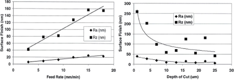
Hardened bearing steels such as M50 were ground to produce an optical quality surface, finer than 10 nm in Ra, using a 76 μm CBN grain size and 500 μm depth of cut, as shown in Figures 7.31 and 7.32. The final surface roughness was reduced by the burnishing action of the worn CBN grits. ELID grinding was employed to reduce surface roughness by maintaining the protrusion and sharpness of the CBN grits and to avoid the pullout of carbides in the secondary finishing zone phenomenon.
Figure 7.31Surface finish versus feed rate and depth of cut [27]
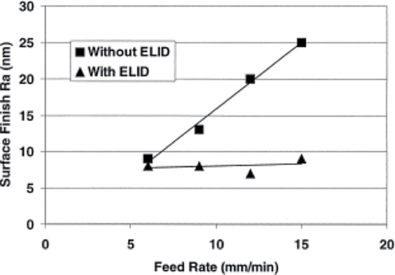
Figure 7.32Surface finish versus feed rate for ELID and non-ELID grinding [27]
Another grinding technique employed to minimize microcracking, surface burn, and phase transformation is low-stress grinding (LSG). However, LSG places special demands on machine tool stiffness, low and controllable vibration levels, low wheel speed, and frequent wheel dressing. LSG is characterized by low removal rates, low grinding ratios, and significantly increased production costs. Also, it was found that some localized surface damage and surface roughness in the range of Ra 100–200 nm were obtained.
Onchi and colleagues reported a roughness of Ra 30 nm achieved after grinding of SAE 52100 with a porous CBN wheel, yet with relatively low removal rates and very fine CBN grits [29].
After superfinishing hardened steel pieces with #500 grit size fused-alumina stones, Puthanangady and colleagues reported a surface finish parameter Ra of up to 60 nm [30].
In another instance, Stephenson and colleagues employed CBN grinding wheels having 30 μm grain size for roughing, 2 μm grain size for intermediate finishing, and 0.7 μm grain size for the final mirror finish [27].
A 100 mm–diameter D151 electroplated diamond wheel at 3000 rev/min was employed with a traverse rate of 5 mm per revolution and an in-feed of 1–4 μm per pass. The electrical power supply parameters were 60 V, peak current of 10 amps, on-time 6 μs, and off-time 2 μs with a square pulse wave.
Important findings are described here:
• A repeatable surface roughness less than Ra 10 nm was obtained with 75 μm CBN grit and 500 μm depth of cut.
• The lowest surface roughness of Ra 2.3 nm was obtained with a 200 μm depth of cut.
• Chip thickness was estimated at 1–10 nm.
• Carbide pullout of the CBN grits could be avoided by employing ELID dressing.
• Optical quality surfaces were considered to have been obtained by a combination of processes in the primary and secondary finishing zones of the cup wheel, with the final surface finish enhanced by the burnishing action of worn CBN grits.
ELID Mirror Grinding of Carbon Fiber-Reinforced Plastics [28]
Carbon fiber-reinforced plastics (CFRP) are used in the aerospace industry and for machine tool spindles, power-transmission shafts, and robotic arms. It was found that:
• Surface roughness of the CFRP improved substantially for grinding with diamond wheels of increasing mesh number up to #4000.
• For diamond wheels having mesh number greater than #4000, roughness did not noticeably improve.
• The upper limit of surface roughness for a #6000 wheel was Rmax 0.65 μm.
• Surface roughness obtained for CFRP was finer than for brittle materials ground under similar ELID conditions, which was explained by the elastic deformation of this material.
• Mirror-finish is strongly dependent on the grinding direction. Grinding at 90° with respect to fiber direction favors the best results.
• The sparkout effect on roughness was significant for rapid-feed grinding but small for creep-feed grinding.
• Mirror-finish is accompanied by a homogenization mechanism resulting from grinding heat and chip smearing.
ELID Grinding of Chemical Vapor–Deposited Silicon Nitride [4]
Chemical vapor–deposited silicon nitride (CVD-SiC) is the second-most ideal material for deflection mirrors used in short wavelength laser systems, surpassed only by the crystalline diamond. Conventional polishing techniques were unable to finish CVD-SiC mirrors. The study concluded that:
• ELID grinding can achieve extremely smooth surfaces.
• Surface roughness reduced with grain size.
• Fewer pits and whiskers were produced in ELID grinding during brittle fracture when the abrasive grains crush and plow the surface of the workpiece compared to other dressing techniques. The number of pits and whiskers reduced with decreasing grain size.
• The ratio of the ductile- versus brittle-fracture mechanisms was higher for ELID grinding than for conventional dressing. The ratio increased with decreasing grain size.
• Ductile-mode removal was realized with ELID, even on a conventional less-stiff and less-precise grinder, by optimum control of depth and composition of the insulating oxide layer.
7.10. Conclusions
During the last decade, a number of publications demonstrated the merits of ELID for abrasive grinding of brittle materials such as common advanced ceramic materials, BK-7 glass, and fused silica, ceramic coatings, and hard steels, as well. Materials have been ground in various shapes and sizes: plane, cylindrical external and internal, spherical and aspherical lens. For some applications ELID grinding eliminated polishing and/or lapping operations.
ELID grinding provides the ability to produce extremely fine finish on brittle material surfaces, with surface roughness on the nanometer scale (4–6 nm). Yet, coarse grit size wheels (JIS #325 and coarser) show only slight, if any, difference in the final roughness when ELID is applied compared to conventional grinding. However, for finer wheels (JIS #4000 and finer), ELID gives finer surface roughness compared to conventional grinding.
ELID grinding is more stable than conventional grinding, allowing high removal rates over a longer period. Material removal rates between 250 mm3/min and 8000 mm3/min were reported, with specific stock removal rates of 25–800 mm3–mm/min.
The use of cast iron-bond wheels resulted in both a larger stock removal rate and a lower grinding force than vitrified-bond grinding wheels.
ELID grinding can be completed in brittle-fracture mode for coarse wheels and in a ductile mode for finer wheels (JIS #4000 … #20,000, FEPA #1200 and finer). By carefully selecting the grinding parameters and controlling the process, ceramic materials can be ground predominantly in a ductile mode resulting in relatively smooth grooves on the surface.
Ductile-mode grinding can be implemented on a conventional grinder by controlling the wheel topography. ELID grinding can be implemented even on low-rigidity machine tools and for low-rigidity workpieces.
Cutting speed and feed-rate were proven to have little effect on workpiece surface final roughness.
Grinding forces are lower during ELID grinding than during conventional grinding. Grinding force was found to be relatively constant and decreased in value after the first ELID dressing stage was completed.
Fine ELID grinding induces compressive surface stress of about 150–400 MPa. The depth of the compressive layer produced during ELID grinding may be half that of one produced during honing. For example, 10 μm depth was produced after ELID fine grinding as compared to 15–20 μm produced after honing.
Hardened bearing steels can be ultraprecisely ground to produce optical quality surface characterized by Ra 10 nm or less. The final surface roughness is enhanced by the burnishing action of the worn grits.

 (7.1)
(7.1) (7.3)
(7.3)