Chapter 5

Honing and Superfinishing

Eckart Uhlmann*
Günter Spur
Michael Kleinschnitker
*    Institute of Machine Tools and Factory Management, Technical University Berlin,
Chair of Machine Tools and Manufacturing Technology, Berlin, Germany

Abstract

In this chapter the mechanical finish-machining manufacturing processes honing and superfinishing are characterized. A description of the typology of these processes in terms of different kinematics and a brief overview over the different honing and superfinishing tools is given. The structure, dimensions and conditioning of honing tools are explained. Furthermore modern honing and superfinishing machines are specified and the honing technology for ceramic materials is shown. Therefore the influence of different process parameters and tool specifications on the process performance is demonstrated through experimental results. For the demands of high specific material removal rates as well as high surface quality a multistage process with more than one honing stone specification needs to be implemented. Additionally the double face grinding process is described in this chapter because of the similar relative movement of the abrasive grains on the workpiece. Double face grinding with planetary kinematics has a high relevance for plane-parallel processing of ceramic materials, like fuel pump lids and regulating wheels.

Keywords

Honing
Superfinishing
Double Face Grinding
Long-Stroke honing

5.1. Typology of the honing process

Honing is a technology for mechanical finish-machining of metallic parts and brittle-hard ceramic. According to DIN 8589 T14 [1], honing is defined as cutting with geometrically undefined cutting edges, during which multiedge tools conduct a cutting motion consisting of two components. At least one component of the cutting motion is a stroke motion, so that the machined surface shows defined crossing traces. Shape elements machinable with honing are determined by the technological variants: plane, cylindrical, screw, hob, profile, and form honing. The shape elements are machinable inside and outside. An additional subdivision of the technology into long-stroke honing and superfinishing is undertaken in relation to the cutting motion. During superfinishing, also described as short-stroke honing, a rotary motion is overlapped with a short-stroke oscillating motion. The cutting motion during long-stroke honing consists of a rotary motion and a long-stroke oscillating motion.
Honed surfaces show good tribological properties. High contact ratios and low roughness in connection to the defined crossing canals, which can absorb lubricants, improve the running-in characteristics and increase the life of tribologically stressed parts. In addition to the high surface quality, the technology of long-stroke honing makes it possible to produce internal cylindrical surfaces with high dimensional and form accuracy. Fields of application include the finish machining of slide bearings, cylinder liners, and piston cylinders. For short-stroke honing, fields of application open up where highly stress-resistant parts with high surface quality and high form accuracy are required. Here, friction and sliding surfaces, parts of antifriction bearings and slide bearing pivots, as well as sliders and seats of packing rings, and collars are machined.
During the production of the mentioned parts from ceramic materials, the suitable parameters that were determined for honing of metallic materials are not transferable due to their principally different ceramic-specific material properties and cutting mechanisms. The part quality required for tribological stress (and at the same time, gaining high tool lifetimes and shorter machining times while minimizing costs) calls for an adjustment of input quantities on the machined ceramic materials, which are summarized for long-stroke honing in Figure 5.1.
image
Figure 5.1 Process parameters of long-stroke honing [2]

Kinematics of Long-Stroke Internal Circular Honing

The cutting motion during long-stroke internal circular honing is created by a stroke and rotary motion of the tool (Figure 5.2).
image
Figure 5.2 Kinematics of long-stroke honing; (a) top dead center, (b) bottom dead center [2]
The superposition of stroke and rotary motion leads to the formation of intersection machining marks, which are characteristic for honing and intersect under the honing angle α (Figure 5.3).
image
Figure 5.3 Cross-traces during long-stroke honing: (a) simplification, (b) honed ZrO2 surface [2]
The cutting speed vc and the honing or intersecting angle α are calculated based on the circumferential speed vu and the axial speed vh with:

vc=vh2+vu2

image (5.1)
and

α=2arctanvhvu

image (5.2)
The circumferential speed vu is calculated based on the workpiece diameter dwst and the rotational speed of the workpiece n with:

vu=πdwstn

image (5.3)
The chosen honing angle influences the ability of the surface to absorb lubricants and hence, tribological stresses can be reduced. Extensive empirical tests in engine construction have led to a definition of suitable honing angles for metallic functional parts. For ceramic materials, different cutting mechanisms are active due to their different material properties and thus, the created surface topography cannot be compared to the one of metallic materials. For this reason, suitable honing angles, which were determined for metallic surfaces, are not necessarily applicable to ceramic surfaces. Publications on the determination of a suitable honing angle in relation to the tribological conduct of ceramic surfaces are not yet known.

Stroking Reversal Points

The position of stroking reversal points, also described as honing stone overflow, has a significant influence on the cylindricity of the honed surface. In order to achieve cylindrical shapes of bore, the overrun length should be one third of the honing stone length on the upper and lower stroking reversal points during machining of both metallic and ceramic materials [3].

Kinematics of Superfinishing

During short-stroke honing, a close-grained honing stone with an encircling angle of 60°–70° is pressed on the circulating workpiece, and thus set into oscillation parallel to the machining surface (Figure 5.4a). The stroke length of the honing stone is 1–6 mm at 1000 to 3000 oscillations/min, which are produced by compressed air or electromechanical means [4].
image
Figure 5.4 Kinematics of superfinishing: (a) kinematics, (b) simplification [4]
The stone pressure is chosen relatively low between 10 and 120 N/cm2 and is usually created by compressed air. This way, the material removal is carried out gently without an alteration of the surface structure by contact forces and temperature.
Sinusoidal machining traces result from the rotation of the workpiece and the oscillating motion of the honing stone, which cross at the change of direction during the stroke. Figure 5.4b shows the development of a path curve of a cutting grain relative to the workpiece.
Investigations have shown that a higher productivity as well as better results with regard to roundness and surface quality can be attained by the application of higher circumferential speeds of the workpiece, which are 10–600 m/min.

Ream Honing

The machining of ceramic parts is, in addition to conventional honing, also possible with ream honing. During ream honing, a honing tool adjusted to its final dimensions is used. Therefore, a feed system of honing stones is not needed. The cutting process is usually performed with one to a maximum of three double strokes. Although the stroke speed is lower compared to conventional honing by a factor of 5–10 (vh = 2 – 6 m/min), the values for the circumferential speed are in the range of conventional honing (vu = 30 – 50 m/min) [5,6]. The higher form stability of the firmly adjusted tool is the advantage of ream honing. Hence, compared to conventional long-stroke honing, it is now possible to achieve a higher dimensional and form accuracy. Small drillings up to a diameter of 1.5 mm, as well as interrupted drillings and step drillings can be machined with high accuracy. An adjustment of honing stones for the purpose of wear compensation is also possible; it is carried out manually or automatically by a feedback regulation. In order to prevent an overstress of the honing tools (Figure 5.5), only a few micrometers of material can be removed with one tool during ream honing. Consequently, it is necessary to design ream honing as a multistage process, or to have a conventional honing process precede the ream honing in order to achieve the required material removal.
image
Figure 5.5 Tools for ream honing for different application [7]

5.2. Honing and superfinishing tools

Interior honing tools fill the bore and lean equally over the honing stones at the circumference of the bore (Figure 5.6). The honing stones are fed by a double cone, which converts the axial feed motion of the pressure bar into a radial motion of the honing stone support. These honing stone supports, onto which the honing stones are soldered, adhered, or clamped, are situated in the radial slots of the tool base. Multiple-stone honing tools are available in series for the diameter range of 5–1000 mm.
image
Figure 5.6 Structure of a long-stroke internal circular honing tool [2]
The potential machining diameter of a honing tool is determined by the cone angle as well as the height of honing stone support and the honing stone itself and is only a few millimeters. A conditioned honing tool has a limited operating range, because the outer radius of honing stones is coordinated with the radius of the honed bore. Figure 5.7 shows the schematic description of the feed system and the taking-up of the honing stone onto the oscillating device during short-stroke honing.
image
Figure 5.7 Tool and feed system for short-stroke honing [4]

Structure of Honing Stones

Diamond and CBN-honing stones are used for the honing of ceramic materials. The characterization of honing stones with regard to grain and bond specification is done in the same way as is the characterization of diamond and CBN grinding wheels. The grain sizes of diamond grains are not designated in mesh (in the number of meshes per inch screen length). The grain sizes can be more accurately understood by correlating them to their respective mesh sizes and grit size scatter in diameter. For the designation of the quantity of diamond grains in the honing stone, the diamond quantity is given in a percentage in relation to 4.4 Carat/cm3. Hence, a honing stone of 100% concentration contains 4.4 Carat/cm3, respectively 0.88 g/cm3 diamond. In addition to bronze-bonded honing stones, ceramic and epoxy resin-bonded honing stones are also applied.

Dimensions of Honing Stones

An improvement in form accuracy of the workpiece surface is usually another objective of honing. Hereby, the length and width of honing stones used play a significant role. Whereas long honing stones reduce the cylindricity deviation, wide honing stones can diminish the roundness deviation [8]. Because the chip transportation is more difficult with an increasing width of the honing stones, additional scavenging grooves are also created in the lining during the application of wide honing stones. At a tool overflow of one-third of the length of honing stones, the suitable length of honing stones should be theoretically four-thirds of the height of the honed bore. Under this condition, the total length of honing stones engages during one stroke. Practically however, the length of honing stones is often in a range of one-half to one-fifth of the workpiece height.

Conditioning of Honing Stones

Diamond honing tools are usually profiled by grinding with bakelite-bonded silicon carbide grinding wheels. The following grinding parameters have proved to be favorable [9]:
Cutting speed vc:    1 – 3 m/s,
Grinding wheel:    hardness J/K
SiC 400/280 for grain sizes up to D64
SiC 240/100 for grain sizes D76–D126
SiC 80/40 for grain sizes D151–D256
Wheel dimensions:    500 × 50 mm
Rotational speed of honing tool vw:    ca. 20 min−1
Feed speed vf:    ca. 720 mm/min
Cooling lubrication:    Emulsion, dropwise
After the grinding process the grains and the bond are in one plane, so that grinding of honing stones leads to a minor grain overflow. A sharpening of honing stones is generally necessary prior to application. The honing stone bond is hereby moved back by manual lapping or by using SiC-sharpening stones.

Conditions for Cooling Lubrication

Cooling lubrication in honing has a significant influence on the work result. The cooling lubricant must be matched with the material to be honed and the honing stone specification. The task of the cooling lubricant is, on the one hand, to clean the workpiece and tool by rinsing off chips and broken-out diamond grains. On the other hand, the lubrication prevents the heat development between the two moving surfaces. Honing oils, water-mixed cooling lubricants, or emulsions can be used as cooling lubricants for ceramic machining. However, the effects of additives used during honing of metals cannot be applied to ceramic machining, especially in the case of additives such as chlorine, phosphorus, and sulfur [10] that are activated by a chemical reaction with the metallic material.
The cleaning of the cooling lubricant is significant for the achievement of constant work results. By means of a filter device, it must be controlled such that no abrasive ceramic chips and broken-out diamond grains are flushed back onto the workpiece surface and cause scratches. At the same time, the cooling lubricant circulation components themselves must be protected against abrasive chips by filters [11]. A temperature regulation of the cooling lubricant is imperative because larger quantities of heat are set free during honing of ceramics, particularly during realization of high material removal rates. This way, the viscosity of the cooling lubricant can be kept constant and the work result of the honing process can be reached independent of the machining time.

5.3. Honing and superfinishing machines

The great variety of honed units and parts on the market has led to various construction forms of honing machines. Measuring and controlling tasks in various honing machines, too, became much more complex under the aspects of automation and process security during production of highly accurate bores. Thus, feed of honing stones, measuring and verifying systems, stroking and rotating drives, positioning axes, as well as the tool changer and the tool magazines can be integrated in numerically controlled machines (NC/CNC).
The diverse construction forms can be divided according to the machined workpiece dimensions such as length and diameter of bore, or to the number and position of the main spindles. Machines with a vertical hone spindle are favored in most cases because they are free from influence by gravity of the tool and driving rod, and flexible honing tools and cardanic workpiece uptaking devices can be used [3]. Moreover, the feed of honing oil and chip removal are facilitated. Machines with a horizontal spindle are also used, particularly for extremely small and extremely large workpieces.
Horizontal manual and lifting beam honing machines (Figure 5.8a) are considered to be simple honing machines and are especially applied to the production of small or medium series in workshops [3]. They are characterized by their simple structure and broad application possibilities. A pedal or feed nut is used for the manual feed of the tools.
image
Figure 5.8 Long-stroke honing machines [12]: (a) lifting beam honing machine, (b) production honing machine (small-batch), (c) production honing machine (large series), (d) vertical pipe honing machine, (e) horizontal long-pipe honing machine
Vertical production honing machines in Figure 5.8b and c are offered in C-structure or portal construction, and are generally considered to be typical construction forms of long-stroke honing machines. The degrees of freedom between workpiece and tool, together with the forces active during honing, determine the selection of the simpler and better available C-structure, or of the more stiff portal construction. In the case of the C-structure, the spindle is taken up in a protruding upright, whereas in portal constructions, it is taken up in a case that is supported on both sides. The machine table is designed for both construction forms as either a fixed, round, or NC-table. Particularly for multiple spindle honing machines, manual or automatic loading devices and transfer systems serve the purpose of a flexible feeding, while industrial robots are also used more frequently.
Vertical pipe honing machines as in Figure 5.8d are used for lifting heights up to 4500 mm [3]. In machines designed in flask mold with spindle support, the workpiece looms into an engine pit underneath the honing machine. This underfloor construction keeps the overall height low. Slide times can be shortened by application of slide tables with two uptaking devices.
Heavy honing machines are also installed over an engine pit. The machines, which are often designed in portal construction, serve to machine large, bulky workpieces such as cylinder liners of diesel engines and press cylinders. The automation becomes particularly important for special honing machines, especially multiple spindle machines, where the safe feed of workpieces is significant in addition to the automatic functional process with measuring devices.
Horizontal production honing machines serve, for instance, to machine crankshaft bearing bores and cooling compressors. Smaller workpieces such as planet-toothed wheels are honed together at the same time [3]. The horizontal long-pipe honing machine in Figure 5.8e represents another construction form, which is built today for honing lengths up to 12,000 mm and machining diameters up to 1,000 mm. Long steel pipes, gun pipes, and chills are produced with these machines. In order to develop the machining independent of gravity, the workpiece moves in the opposite direction to the tool. Moreover, a purposeful feed of the cooling lubricant is necessary. High driving powers of approximately 40 kW each for stroking and rotary motion are characteristic for these machines.
With regard to short-stroke honing machines, the opportunities for application range from the machining of small bearings with diameters of 5–10 mm to high-finished and absolutely channel-free rollers of more than 1000 mm in diameter for the production of sheets, films, and qualitative bands.
Automatic short-stroke honing machines in series production are mostly equipped with automatic feed devices, but it is necessary to distinguish between the particularly economic continuous machining and plunge-cut machining. During continuous machining, workpieces are brought into a rotary and feed motion between tilted rollers rotating in the same direction, and transported under the oscillating honing stones [13]. Due to the gradation of grain size of the cutting material bound in the honing stones, significant material removal as well as a high surface quality can be reached. The use of powerful oscillating heads allows continuous speeds of up to 6 m/min; the applications include needle bearings, axes, axles, rollers, and piston pins. An automatic removal of honing stones during the process is required for workpieces with differently shaped elements on the circumference, for example piston rods of telescopic legs. Hereby, workpieces are scanned by sensors and the honing stones are only lowered onto those positions on the workpiece to be machined.
Tapered rollers and gear shafts are machined, for example, with plunge-cut machining, either centerless or between centers. Because the automation of the process is costly, plunge-cut technology is only possible for smaller piece numbers.
Band honing machines (Figure 5.9) are also short-stroke honing machines and are characterized by a number of side-by-side, simultaneously honable machining positions [3]. This honing is achieved by various flexible honing arms, each of which press a honing band that embraces the machining positions and can be tightened. Furthermore, a short stroking motion in the axial direction is overlapped by rotation of the workpieces. Gear, crank, and camshafts can be machined with band honing machines, which are often designed in portal construction.
image
Figure 5.9 Band honing machine: (a) two-stage bandfinishing of shafts, (b) two-stage bandfinishing of crank shaft [14]

Degrees of Freedom Between Tool and Workpiece

The degrees of freedom between tool and workpiece are decisive for the opportunities of correction of form and position during the honing process; they are determined by the positioning of tool and workpiece. Potential forms of position are the double cardanic, cardanic, swimming, or solid position. A restriction in the degrees of freedom leads, starting with an improvement in roundness and cylindricity by the honing process, to an improvement in the right-angularity of a bore. Moreover, it results in an increase in the accuracy of position of a bore at further restriction (Figure 5.10). However, a high stiffness of the system is required.
image
Figure 5.10 Degrees of freedom between tool and workpiece [15]

Feed Systems of Honing Stones

The radial feed of honing stones against the workpiece serves on the one hand to adjust the machining allowance of the material and, on the other, to compensate the wear of honing stones. It is important to distinguish between force-activated hydraulic and way-activated mechanical feed systems for long-stroke honing (Figure 5.11).
image
Figure 5.11 Feed systems of honing stones for long-stroke honing [2]
Hydraulic feed systems transform oil pressure into feed force by means of a piston. This feed force is transferred to the honing stones via a pressure bar, double cone, and honing stone support. The stone pressure ps is a parameter for the description of the feed force. It describes the surface pressure between honing stone and workpiece. Recommended values for diamond honing stones for metal machining are ps = 1–8 N/mm2 [3].
At a force-activated hydraulic feed, the machining allowance cannot be adjusted directly. The selected honing parameters lead to a constant material removal referred to as the honing time. The machining allowance is regulated by the honing time. In order to produce narrow diameter tolerances, it is necessary to determine the workpiece diameter during the process. The honing process ends when the nominal diameter is reached. Special honing tools can be used in order to detect the actual measure of the bore. For these tools, the quantity of air that escapes from pneumatic jets on the tool circumference serves to define the actual bore diameter. During application of way-activated feed systems, honing stones are fed with defined feed steps in a range of 10–100 micrometers [5]. The feed usually progresses in a number of partial feed steps.

5.4. Honing technology

Honing-in Performance

During the cutting of ceramics, constant cutting conditions are often impossible to achieve. The honing process is characterized by a honing-in behavior of the honing stones. The initially sharp cutting grains blunt with increasing machining time, which consequently leads to a decreasing material removal rate. Depending on the machined material and the implemented honing stone specification, constant cutting conditions appear after a certain time; the honing stones operate in the self-sharpening range, or they lose their cutting ability until no further removal can be reached and the stones must be sharpened. Figure 5.12 shows the honing-in behavior during machining of SiSiC. Although close-grained honing stones D3 and D7 show a constant performance after a short honing-in time, the specific material removal rate at grain size D15 goes back to zero in the first 500 s. Yet, only a relatively low specific material removal rate can be reached with close-grained honing stones, which is not sufficient for economic machining.
image
Figure 5.12 Honing-in behavior of various honing stone grain sizes [16]

Honability of Ceramics

As can be seen in Figure 5.13, the specific material removal rate related to the surface depends on the size of the diamond grain and of the stone pressure during machining of A12O3 and ZrO2. While diamond grain size D3 does not allow efficient material removal during the machining of the chosen Al2O3-material, all diamond grain sizes above D3 can be implemented. However, the application of diamond grain sizes exceeding D10 leads to significant heating of the tool and of the workpiece. In order to avoid damages to the tool and workpiece, the stone pressure is not increased above 2 N/mm2. Here the specific material removal rate increases with increasing stone pressure because the normal force that presses the single diamond grain onto the material increases. The influence of the diamond grain size on the material removal rate, however, does not support such a general statement. At diamond grain sizes below D64, the specific material removal rate increases according to the size of the grain. Especially during the transition from the diamond grain size D10 to D35, a considerable increase occurs in the material volume removed per time unit. The transition from diamond grain size D64 to grain size D126 leads to a reversion of this tendency and thus to a decrease in the material removal rate. This decrease can be explained by a decrease in the number of active diamond grains, while the size of the diamond grains increases. The reduction of the number of grains is connected to an increase in the normal force at each diamond grain. If the increase in the normal force at each grain leads to an underproportional increase in the material volume removed from each grain, a decrease in the material removal rate results.
image
Figure 5.13 Honing A12O3 and ZrO2, with specific material removal rate dependent on grain size and stone pressure [17]
In contrast, material removal from zirconia is only possible with a diamond grain size above D36. At this grain size, it becomes clear that an initial pressure must be surpassed in order to remove material. This pressure decreases with the growing size of the diamond grain due to the inverse relationship between an increase in the grain diameter at constant diamond concentration and a decrease in the number of diamond grains. This relationship results in high normal forces between each cutting grain and the ceramic material at a low stone pressure. Accordingly, a stationary material removal during machining with small sizes of diamond grains should be obtainable by reducing the diamond concentration, thus also reducing the number of diamond grains.
Figure 5.14 shows the influence of stone pressure and the size of the diamond grains on the removed material volume during honing of SSN. As can be seen, the removed material volume is approximately two decimal powers smaller than during the machining process of oxides. At all honing stone specifications, the material removal begins at stone pressures higher than 1 N/mm2. The removed material volume increases according to the size of the diamond grain. However, the increase in the specific material removal rate is low at the transition from diamond grain size D64 to D125.
image
Figure 5.14 Honing SSN, with specific material removal rate dependent upon grain size and stone pressure [17]
During honing of SiSiC, no constant cutting conditions could be determined at stone pressures below 2 N/mm2. With diamond grain size D3, no significant increase in the specific material removal rate could be reached with increasing stone pressure. In contrast, an increase in stone pressure by 2 N/mm2 for grain size D7 resulted in a quadruple material removal rate. For grain size D15, stone pressures of 10 N/mm2 were necessary in order to achieve constant cutting conditions (Figure 5.15).
image
Figure 5.15 Honing SiSiC, with specific material removal rate depending upon grain size and stone pressure [16]

Influence of Diamond Concentration

During short-stroke honing of the materials SiC, Si3N4, and TiN (Figure 5.16), an increase in the wear of honing stones becomes evident with increasing diamond concentration. This increase can be explained by a reduced strength of the honing layer bond, whose mass is diminished at increasing diamond concentrations, and by a bigger number of free, chipped-off grains that intensify the abrasive wear of the tool. Using low diamond concentrations, the roughness of workpiece surfaces can be reduced. For long-stroke honing, no examinations are known.
image
Figure 5.16 Influence of diamond concentration on material removal rate, roughness, and honing stone wear [18]
The results of the honing stone wear and the roughness of workpiece surfaces, however, do not lead to a uniform dependence for all materials; the irregularities of structure and mechanical properties of the tested ceramics are highly diverse. Deviating results were obtained in particular for titanium nitride due to its increased plasticity.

Influence of Cutting Speed and Honing Angle

Figure 5.17 demonstrates the increase in material removal with increasing cutting speed. A longer cutting path is covered by the single grain at the same time with increasing cutting speed. It proves that the decrease in material removal for honing of metallic materials takes place above vc = 60 m/min for the investigated honing stone and material combination, due to hydrodynamic effects that occur once a certain cutting speed has been exceeded [19].
image
Figure 5.17 Specific material removal rate in relation to cutting speed [15]
Investigations of A12O3 show that, in contrast to metallic materials, no honing angle can be determined at which the specific material removal rate reaches a maximum. The change in specific material removal rate at an alteration of the honing angle is low when compared to a change in cutting speed, stone pressure, or diamond grain size (Figure 5.18).
image
Figure 5.18 Specific material removal rate in relation to honing angle [15]

Influence of the Material Specification on Honing of Alumina

Indentation hardness tests and scratch tests with different diamond geometries, as well as machining tests, revealed a clear relation of the working result to machining conditions and properties of the ceramic material. Particularly the grain size of the ceramic material had a significant influence during tests with A12O3 and different diamond grain sizes.
Figure 5.19 shows that during honing of A12O3 the diamond grain size D10 can only be used for material removal of smaller A12O3 grain sizes. Using diamond grain size D35 and D64 during the machining process, the removed material volume increases at all examined material specifications compared with diamond size D10. In contrast, at all examined A12O3 specifications, the specific material removal rate decreases considerably under application of diamond grain size D126 compared to D64. A relation of the removed material volume to the A12O3 grain size and to other determined material parameters could not be detected for diamond grain sizes D35, D64, and D126.
image
Figure 5.19 Influence of A12O3 grain size on specific material removal rates [17]
The next section shows that it is possible to explain the relation of the specific material removal rate to the size of the alumina grain under application of small diamond grain sizes based on removal mechanisms that occur during honing.

Influence of Machining Conditions on the Surface Formation of Alumina Oxides

Due to the higher normal forces on the individual cutting grain, Figure 5.20 demonstrates that intercrystalline grain chippings are predominant for honing A12O3 with the bigger grain sizes D35 and D64. The low normal force active for diamond grain size D10 leads to intercrystalline grain chippings only at low alumina grain sizes. Bigger alumina grain sizes cannot be removed during the active lower stress; instead, a smoothing of the surface is caused here by microplastic deformations. Therefore, roughness values decrease under usage of diamond grain sizes D3 and D10 with increasing alumina oxides grain size, while at the same time, the specific material removal rate related to the surface diminishes. For diamond grain sizes D35, D64, and D126, microplastic deformations emerge as a result of the increasing normal force of the single grain, which leave traces along the direction of motion of single grains. Simultaneously, intercrystalline grain chippings also occur at bigger A12O3 grain sizes. These chippings cause an increase in the roughness with the Al2O3 grain size because bigger, chipped-off grains leave bigger flaws.
image
Figure 5.20 Roughness and surface generation, depending on A12O3 grain size [20]

Summary

It is evident that, for the economic honing of metals and ceramics, the demands for a high specific material removal rate as well as high surface quality are not met with a single honing stone specification. The realization of the honing process as a multistage process is necessary, because for ceramics, the decrease in stone pressure does not lead to a significant improvement in the surface quality. Although necessary material removal is achieved in the first stage, the required surface quality can be produced in the following stages. The finish machining of circulation pump bearings made of aluminum oxide is one example of such a multistage process (Figure 5.21).
image
Figure 5.21 Honing of ceramic bearings made of A12O3 [21]
This multistage process can either be realized on a multispindle honing machine or by application of a honing tool equipped with two sets of honing stones. By means of two separately operated pressure bars, honing stones are led in series to engagement during rough and finish honing.
Experimental tests were also undertaken for ceramic cylinder liners made of A12O3, ZrO2, and dispersion ceramics (Figure 5.22). The main objective was the reduction of the interabrasion in the reserving range of the piston by the use of ceramic liners. High demands were placed on the honing process in terms of the bore shape and surface quality. A 5 μm taper must be secured for the cast iron as well as the ceramic components over the entire length of the bore. Also, the surface parameter Rz of the ceramic components must be 2 μm lower than of the cast iron. The technological investigations were carried out with diamond honing tools. The requirements could be achieved with the dispersion ceramics whereby the measured surface parameter Rz was about 3 μm.
image
Figure 5.22 Honing of ceramic cylinder liners made of A12O3, ZrO2 and dispersion ceramics [12]

5.5. Double face grinding

Eckart Uhlmann and Michael Kleinschnitker

Introduction

Technical components with coplanar functional surfaces and high demands on evenness can be found in various technical applications, including control wheels, seal disks, and bearing rings. The components may vary regarding their geometry, material, or application. Manufacturing technologies that allow simultaneous processing of both functional surfaces, such as double face grinding, are most suitable for machining such workpieces.

Process Description

The most commonly implemented process in the industrial field for double face machining of ceramic workpieces is double face grinding with planetary kinematics. This machining process represents a logical improvement of the lapping technology. For processing, the workpieces are placed in circular outward-teethed workpiece holders, so-called rotor discs. These discs are placed between two grinding wheels, held in place by a fixed outer pin ring and driven by a rotating inner pin ring. The circular motion of both tools combined with the rotation of the inner pin ring creates a relative velocity between tools and workpieces analogous to the kinematics of epicyclical gears. In comparison to other processes, for example longitudinal face grinding or plunge face grinding, double face grinding with planetary kinematics offers a lot of advantages. The process allows tension-free mounting as well as a constant stress over the entire functional surface of the workpieces. A schematic setup for double face grinding with planetary kinematics is depicted in Figure 5.23.
image
Figure 5.23 Setup for double face grinding with planetary kinematics [22]
The machining process of double face grinding with planetary kinematics differs from other grinding operations due to its setup and kinematics. Because of the special kinematics caused by the superposition of the described three motions, the workpiece surfaces exhibit undefined as well as interfering grinding marks. Furthermore, excellent surface qualities regarding roughness and flatness can be achieved. An additional advantage of this process is the equally distributed stress on the functional surface of the workpieces during grinding [2233].
A number of determining parameters characterize the process of double face grinding with planetary kinematics. These parameters are the process force Fp, the revolution of the lower grinding wheel nl, the revolution of the upper grinding wheel nu, the revolution of the inner pin ring ni, and the resulting revolution ratio NL (Figure 5.24). The revolution ratio NL is the quotient of the speed of the lower tool nl and the inner pin ring ni. Moreover, the average size of the abrasive grain D, the grain concentration C, the cooling lubricant flow rate Q, and the allocation of the grinding wheel B are important parameters to describe the process [22,23,24,29].
image
Figure 5.24 Most important process parameters in double face grinding with planetary kinematics
Furthermore, the arrangement of the workpieces in the workpiece holder can influence the processing results. Experiments have shown that an optimized arrangement of workpieces in the holder leads to an increased removal rate, better surface qualities, and evenness of the workpieces [24,31].
Besides double face grinding with planetary kinematics, other processes are commonly used in the industrial field to machine high-precision workpieces with coplanar surfaces. These processes include plunge double face grinding with a vertical stroke and the grinding wheels arranged in parallel as well as longitudinal double face grinding with tilted grinding wheels.
In plunge double face grinding with a vertical stroke and the grinding wheels arranged in parallel, the workpieces are placed between the opened and rotating grinding wheels by a workpiece holder. A schematic setup is depicted in Figure 5.25. During the process, the workpieces are moved by the workpiece holder, which oscillates over the entire abrasive layer. Once the specified size of the workpieces is achieved, the workpieces can be unloaded from the machine by a raised upper grinding wheel. The oscillating motions in the grinding process have a significant relevance to the process regarding the process time, wear on the grinding tool, achievable surfaces, and flatness on the workpieces. Nevertheless, the selection of suitable process parameters is mostly based on practical knowledge of machine tool manufacturers and users. A disadvantage of the machining process is the vertical stroke of the upper grinding wheel, which can lead to temporary force peaks and even shocks. These effects lead to increased grinding wheel wear or, in extreme cases, total destruction of workpieces made from brittle materials such as ceramics [34,35].
image
Figure 5.25 Plunge double face grinding with parallel grinding wheels and vertical stroke Vfa [34]
The machining technology of longitudinal double face grinding with tilted grinding wheels is characterized by the motion of the workpieces. Located in the workpiece holder, the workpieces feed continuously on rotational or translational trajectories through two grinding wheels (Figure 5.26). The angle Tx of the tilted upper grinding wheel defines the final height of the workpieces. Unfortunately, the attainable surface qualities in relation to evenness and plane parallelism are limited as a result of the entrance as well as exit angles. Furthermore, the tilt induces stress to the machined parts, which causes, in certain cases, outbreaks on the workpiece edges. Therefore the ability to machine brittle materials such as ceramics is limited with this process [34,35].
image
Figure 5.26 Longitudinal double face grinding with tilted grinding wheels [34]
Typical workpieces that are machined by double face grinding processes, such as sealing shims, regulating wheels, or valve discs, are depicted in Figure 5.27. An important challenge in double face grinding of ceramic workpieces is reaching a sufficient surface quality by reducing the number of outbreaks caused by local delamination and the revealing of inherent porosity.
image
Figure 5.27 Ceramic fuel pump lids and regulating wheels made from Al2O3
The latest research activities on machining of high-performance materials in the field of double face grinding with planetary kinematics have proven that optimized cutting conditions involve comparably high cutting speeds. This evidence underlines the high potential of high-speed grinding. Within a series of experiments it was possible to increase the cutting speed from 5 m/s in the conventional process to up to 30 m/s in the high-speed process. Furthermore, the material removal rate h˙wimage was remarkably increased for high-performance ceramics such as ZrO2 and Al2O3 under these conditions (see Figures 5.28 and 5.29), and processing time was reduced by more than 80%. While Figure 5.28 shows consistently good results concerning the surface quality Ra for ZrO2 over the cutting speed, experiments with Al2O3 showed a decrease of Ra with increased speed (Figure 5.29). Using high-speed and high-performance machining for ceramic workpieces with coplanar functional surfaces, plane parallelism and evenness, which represent the determining technical characteristics, can be considerably improved [36].
image
Figure 5.28 Influence of the cutting speed vc on the removal rate h˙wimage 
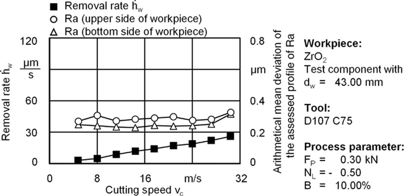
and the surface quality parameter Ra when machining ZrO2
image
Figure 5.29 Influence of the cutting speed vc on the removal rate h˙wimage 
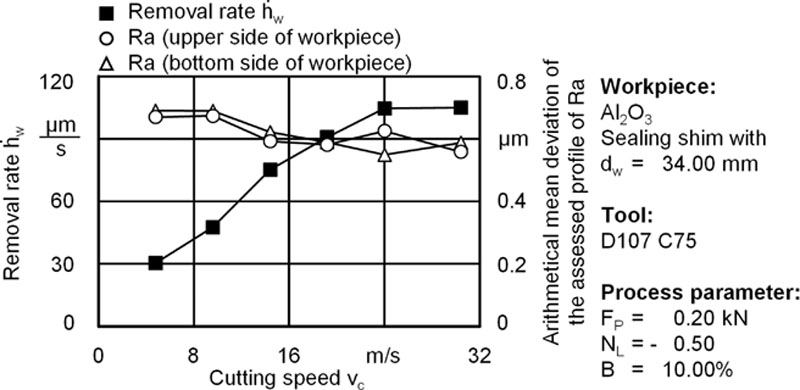
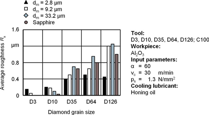
and the surface quality parameter Ra when machining Al2O3

Outlook

In addition to the increase in profitability achievable by raising the cutting speed vc, which was described in the previous section, machining of ceramic workpieces using double face grinding with planetary kinematics can be further improved. Current and future research projects focus on the qualification and design of the process in high-speed applications as well as analysis of the adequacy of this technology when machining advanced high-performance materials. For example, the profile wear, which is dependent on the radius of the grinding wheel due to the special kinematics of the process, must be analyzed; and solutions must be found to counteract this wear phenomenon. Furthermore, the influences of the dynamic properties of the machine on the work result are also an important subject of research and must be analyzed comprehensively. Based on these analyses, the process of double face grinding with planetary kinematics can be optimized. With an improved machining process, the efficiency of machining ceramic workpieces can be increased.

References

[1]  DIN 8589 T14: Fertigungsverfahren Spanen. Teil 14 Honen – Einordnung, Unterteilung, Begriffe. Deutsches Institut für Normen, Berlin: Beuth Verlag; 2003.

[2]  Weigmann UP. Honen - ein Verfahren zur Endbearbeitung keram. Bauteile. Tagungsberichtband zum Fortbildungsseminar “Bearbeiten keramamischer Werkstoffe” der DKG, Berlin: März 1993; 18–19.

[3]  Haasis G. Honen - Handbuch der Fertigungstechnik; Bd. 3/2: Spanen. Hrsg. G. Spur u. Th. Stöferle. C. Hanser Verlag, München, Wien; 1980.

[4]  Baur E. Grundlagen und Anwendung des Kurzhubhonens. VDI Bildungswerk, BW 9807.

[5]  Klink U. Fachgebiete in Jahresübersichten Honen. VDI-Z. 1989;131(9):S. 94-102.

[6]  Spur G. Keramikbearbeitung - Schleifen, Honen, Läppen, Abtragen. München, Wien: C. Hanser Verlag; 1989.

[7]  Klink U. Honen, Fachgebiet in Jahresübersichten. VDI-Z. 1989;131:Nr. 9.

[8]  König W. Fertigungsverfahren. Bd. 2: Schleifen, Honen, Läppen. Düsseldorf: VDI-Verlag; 1980.

[9]  Flores G. Grundlagen und Anwendungen des Honens. Vulkan Verlag: Essen; 1992.

[10]  Boor U. Kühlschmierstoffe zum Honen. VDI-Z 1989;131(5):S. 70–75, Teil 1; 1989;131(6): S. 74–79, Teil 2.

[11]  Gehring: Superharte Schleifmittel. Ostfildern Nellingen (2/72), Firmenschrift.

[12]  Gehring Technologies GmbH, http://www.gehring.de/home/; 2013.

[13]  König W. Stand und Entwicklungen beim Kurzhubhonen. Honen-Anwendung [Hrsg.]. Jahrbuch Schleifen, Honen, Läppen und Polieren. 1974;46:S. 299–314.

[14]  Hildebrand O. Superfinish-Technologie, 222 Band: Verlag Moderne Industrie; 2011.

[15]  Weigmann UP. Honbearbeitung von A12O3 - Einfluβ der Honleistenspezifikation auf die Korrelationen zwischen Werkstoffeigenschaften und Arbeitsergebnis. Vortragsband zum Industriearbeitskreis “Keramikbearbeitung,” Berlin: März 15, 1993.

[16]  Höhne L. Der Werkstoffabtrag beim Honen von Keramik. Honen in Forschung und industrieller Anwendung, Tagungsband, Braunschweig: December 4–5, 1989; S. 174–84.

[17]  Spur G, Weigmann U-P. Influence of the Material Properties on the Honing of Ceramics. XXIII-NAMRC-Conference, Houghton, Michigan, USA: May 24–26, 1995.

[18]  Galkov, A. V.; u.a.: Untersuchung des Kurzhubhonens von Werkstücken aus Keramik auf Karbid- und Nitridbasis mit Diamanthonleisten. IPO. Nauk. dum. 1992;3: S. 54–57.

[19]  Juchem HO. Entwicklungsstand beim Honen von Bohrungen in metallischen Werkstücken mit Diamant und CBN. IDR. 1984;18(3):S. 174–84.

[20]  Spur G, Weigmann U-P. Beeinflussung des Honprozesses durch die Zusammensetzung und die Eigenschaften keramischer Werkstoffe. Beitrag zum DFG-Abschluβkolloquium im SPP “Keramische Hochleistungswerkstoff,” Stuttgart: February 17–18, 1994.

[21]  Klink U. Vollautornatische Honanlagen für Kurbelgehäuse aus AISi 17, Honen von Lagerungen aus Al2O3. Honen in Forschung und industrieller Anwendung, Tagungsband, Braunschweig: S. 129–157, 1989.

[22]  Uhlmann E, Hoghé T. Wear reduction at double face grinding with planetary kinematics. Product Eng Res Dev. 2012;6(3):237 242.

[23]  Ardelt T. On the effect of path curves on process and wheel wear in grinding on lapping machines. In: Proceedings of the 3rd International Machining and Grinding Conference, Cincinnati, Ohio. 1999. p. 307–21.

[24]  Ardelt T. In: Uhlmann E, ed. Einfluss der Relativbewegung auf den Prozess und das Arbeitsergebnis beim Planschleifen mit Planetenkinematik. Berichte aus dem Produktionstechnischen Zentrum Berlin. Berlin: Carl Hanser; 2000.

[25]  Klocke F, König W. Fertigungsverfahren 2: Schleifen, Honen, Läppen. Heidelberg: Springer; 2005.

[26]  Stähli AW. Feinstbearbeitung, Trends der Flachhon und Läpp Technik, Feinstbearbeitung technischer Oberflächen, 4. Internationales IWF Kolloquium ETH Zürich; 1998. S. 47–62.

[27]  Geiger M, Arbak M, Engel U. Material adapted tool design in cold forging exemplified by powder metallurgical tool steels and industrial ceramics. Product Eng Res Dev. 2008;2(4):409 415.

[28]  Funck A. Planschleifen mit Läppkinematik. Berichte aus dem Produktionstechnischen Zentrum Berlin. In: Spur G, editor. Berlin: Carl Hanser; 1994.

[29]  Uhlmann E, Ardelt T, Daus N. Kinematische Analyse von Zweischeibenmaschinen. Werkstattstechnik. 1998;88(6):S. 273–76.

[30]  Uhlmann E, Ardelt T. Influence of kinematics on the face grinding process on lapping machines. Ann CIRP. 1999;48(1):S. 281–84.

[31]  Uhlmann E, Ardelt T, Stingl P, Rußner C, Magg T, Reiser A. Planschleifen mit Läppkinematik. In: Industrie Diamanten Rundschau IDR 1999;33(1): S. 79–83.

[32]  Uhlmann E, Sammler C, Hoghé T, Borsio Klein T. Einsatz innovativer Schleifverfahren macht Hochleistungsbearbeitung wirtschaftlicher. In: Maschinenmarkt Ausgabe 2006;30: S. 22–26.

[33]  Oliveira JFG, Silva EJ, Guo C, Hashimoto F. Industrial challenges in grinding. Annals of the CIRP. 2009;58:663 680.

[34]  Rußner C. Präzisionsplanschleifen von Al2O3-Keramik unter Produktions bedingungen, Dissertation Technische Universität Dresden, 2006.

[35]  Zettel HD. Flachschleifverfahren für Kleinteile aus harten Werkstoffen. In: wt-Z. industrielle Fertigung 1981;71: S. 393–96.

[36]  Uhlmann E, Hoghé T. Hoppla – Entwicklung einer wirtschaftlichen Bearbeitungs-technologie für das Hochgeschwindigkeits- und Hochleistungsplanschleifen mit Planetenkinematik. Berlin: VDI/VDE-IT; 2011.

..................Content has been hidden....................

You can't read the all page of ebook, please click here login for view all page.
Reset
3.145.35.194