Lapping and Polishing
Abstract
The processing technology has beeu applied to the fabrication of optical, electrolic, and mechanical devices. A study on an automatic or computer-aided machining system or both processing and ultraprecision polishing has been undertaken for practical use.
In this chapter, principles of lapping and polishing for hard and brittle materials, like optical glass and crystals belonging to the groop of ceramics, are discussed including the ultraprecision processing technique.
Keywords
6.1. Introduction
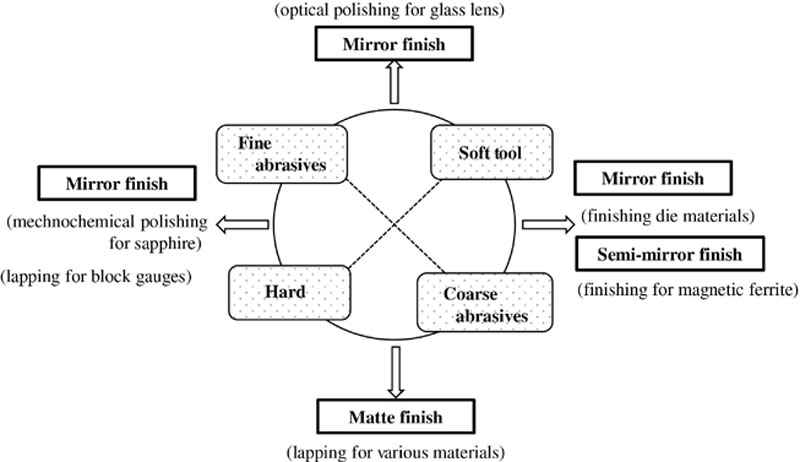
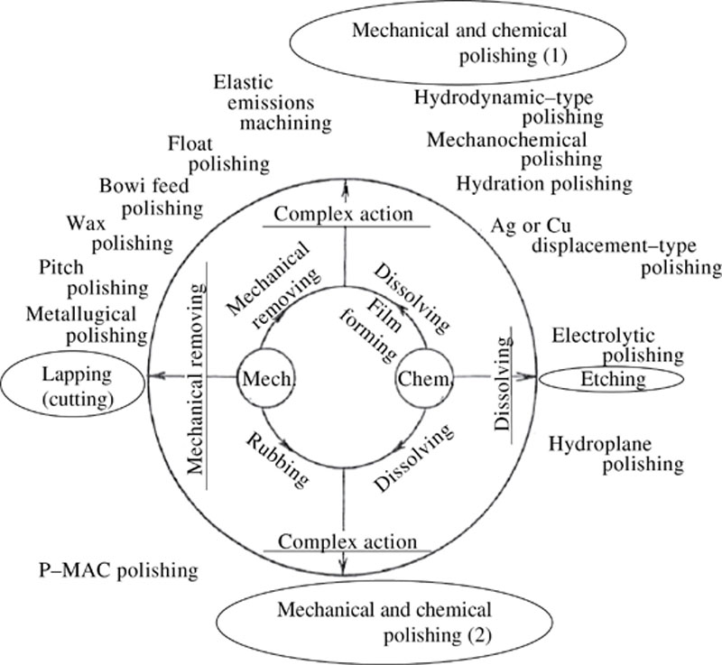
6.2. Typology of processes with loose abrasives
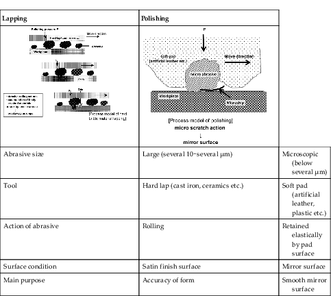
Table 6.1
Difference in processing conditions and the mechanism between the lapping and poslishing
| Lapping | Polishing | |
 |  | |
| Abrasive size | Large (several 10∼several μm) | Microscopic (below several μm) |
| Tool | Hard lap (cast iron, ceramics etc.) | Soft pad (artificial leather, plastic etc.) |
| Action of abrasive | Rolling | Retained elastically by pad surface |
| Surface condition | Satin finish surface | Mirror surface |
| Main purpose | Accuracy of form | Smooth mirror surface |
6.3. Lapping
Lapping Process
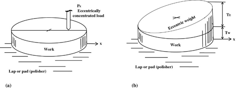
Lapping Factors
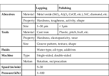
Table 6.2
Main Factors of Lapping and Polishing
| Lapping | Polishing | ||
| Abrasives | Material | Metal oxide (SiO2, Al2O3, CeO2, etc.), SiC, diamond, etc. | |
| Property | Hardness, toughness, activity, shape | ||
| Size | 1–30 μm | < 1μm | |
| Tools | Material | Cast iron | Plastic, pitch, buff, etc. |
| Property | Hardness, elastopasticity, wear | ||
| Size | Groove pattern, texture, shape | ||
| Fluids | Water-type, oil-type, additives | ||
| Machine | Type | Single-sided, double-sided | |
| Motion | Rotation, reciprocation | ||
| Speed (m/min) | 5–30 | ||
| Pressure (kPa) | 1–100 | ||
Abrasives
Lap
Lapping Speed and Pressure
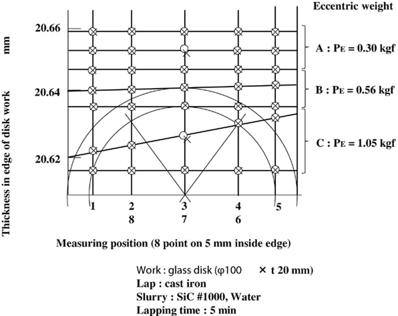
Lapping Characteristics
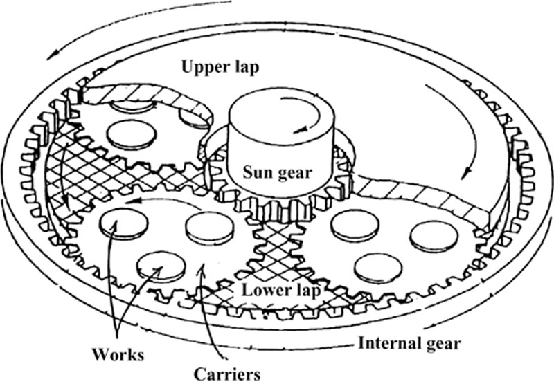
Lapping Machines
6.4. Polishing
Polishing Process and Factors
Abrasives for Polishing
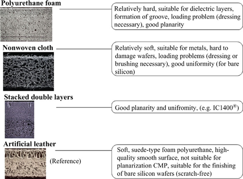
Pad (Polisher)
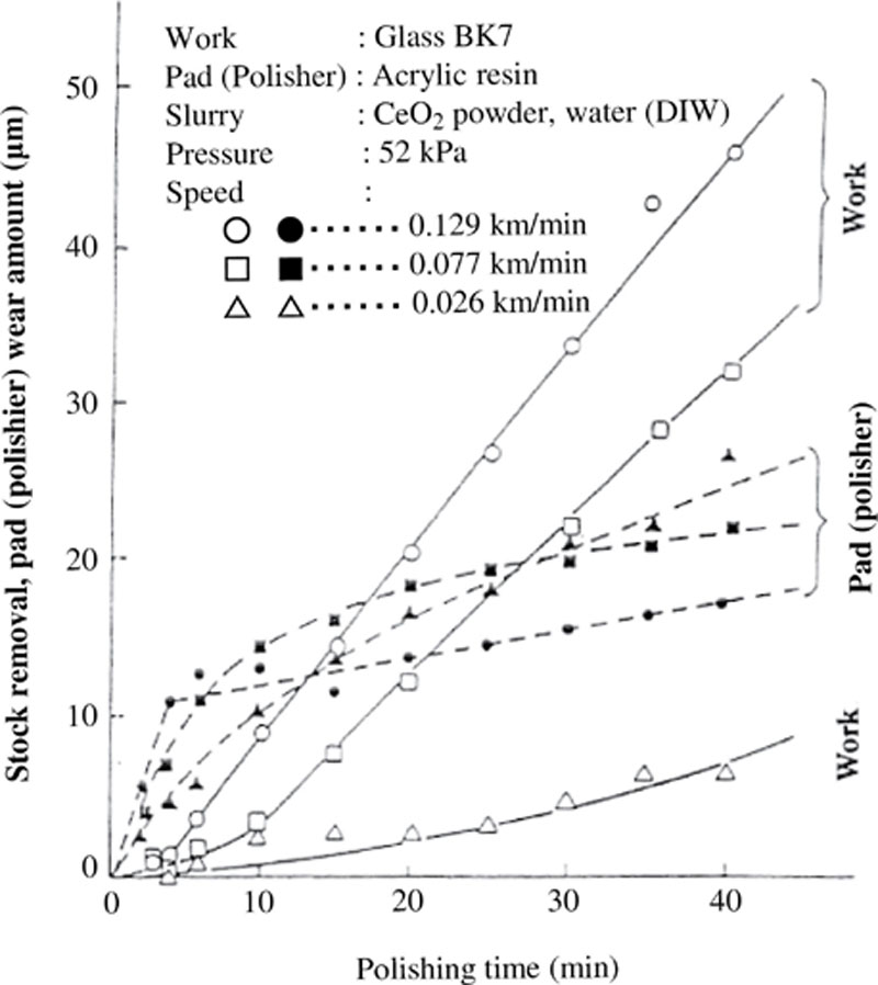
Polishing Characteristics
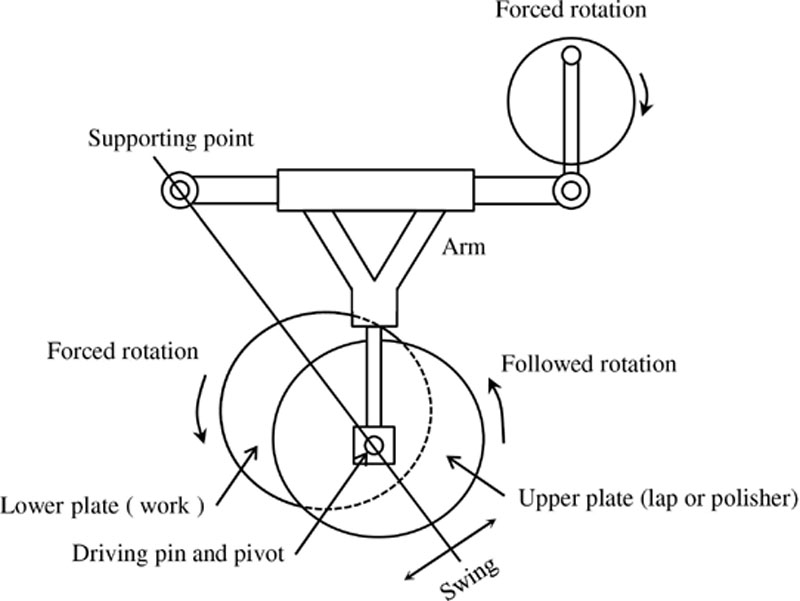
Polishing Machine
Table 6.3
Classification of Lapping and Polishing Machines
| Work | Lap or pad (polisher) | Notes | ||
| Single-sided machine | Flat |
• Force rotation
• Upword |
• Disk plate
• Downward
| Lens lapping and polishing machine |
|
• Forced rotation
• Conditioning ring
• Downward
|
• Swiss and rotation
• Ring (disk) plate
• Upword
| Conditioning ring and type lapping polishing machine | ||
|
• Followed rotaion
• Conditioning ring
• Downward
• Forced rotation
|
• Forced rotation
• Ring plate
• Upward
• Forced rotation
| |||
|
• (Conditioning ring)
• Downward
• Rotation and swing
|
• Ring palte
• Upward
• Forced rotation
| |||
| Motion-free | Oscillation | |||
| Spherical | Lens lapping and polishing machine | |||
| Conditioning-type lapping and polishing machine | ||||
|
•
• Upward
• Forced rotation
|
• Ring (plate)
• Downward
• Swing and rotation
| |||
|
•
• Sideward
• Forced rotation
|
• Ring (plate)
• Sideward
• Swing and rotation
| Advanced curve generator | ||
| Aspherical | Lens lapping and polishing machine | |||
|
•
• Upward
• Computer control rotation
|
• Aspheric tool
• Downward
• Swing and synchronous
• rotation
| |||
|
•
• Upward
• Computer control rotation
|
• Small tool
• Downward
• Circular swing
| Computer-controlled lapping and polishing machine | ||
|
•
• Sideward
• Forced rotation
|
• Small tool
• Sideward
• Forced rotaion and cam drive
| |||
| Double-sided machine | Flat and Parallel |
• Supported by carrier
• Rotation on carrier
and tool center
|
• Lower and upper ring plates
• Fixed
| Two motion–type double-sided lapping machine |
|
• Supported by carrier
• Rotation on carrier and tool center
|
• Lower and upper ring plates
• Either rotation
| Three motion–type double-sided lapping machine | ||
|
• Supported by carrier
• Rotation on carrier and tool center
|
• Lower and upper ring plates
• Opposite rotation
| Four motion–type double-sided lapping machine | ||
|
• Supported by carrier
• Circular swing of carrier
|
• Lower and upper disk plates
• Fixed
| |||
|
•
• Sideward
• Followed rotation by roll supporting
|
• Disk plate
• Sideward
• Both forced rotation
| Magnetic memory substrate double-sided lapping machine | ||

![]()

Advanced Polishing Methods
Table 6.4
Advanced Polishing Methods
| Property of processing | Application | ||
| [Improvement of lapping] | |||
| Ultraprecision | Mechanically stock removing with abrasive stone and oil or water-tyoe solution | Block gauge | |
| Low-speed agrinding | End of scale | ||
| Ultraprecision lapping | By using fine abrasives and metal or ceramics lap, and filtered oil or water-type solution | Plate | |
| Conventional lapping Conventional polishing | By using Al2O3 or SiC abrasives and cast iron lap, or CeO2 powders and pitch or plastic polisher, and lens lapping and polishing machine and conditioning ring-type lapping machine | Glass lens or prism | |
| [Improvement of optical polishing] | |||
| Mech. | Ultraprecision polishing | Suppressing mechanical action and dust influence by adopting fine abrasive powder, soft polisher and (ultra) pure water | Quarts plate Laster rod Optoelectronic device X-ray mirror Large telescope mirror |
| Bowl feed polishing | Work and polisher in slurry for suppressing mechanical action or impact and temperature rise | ||
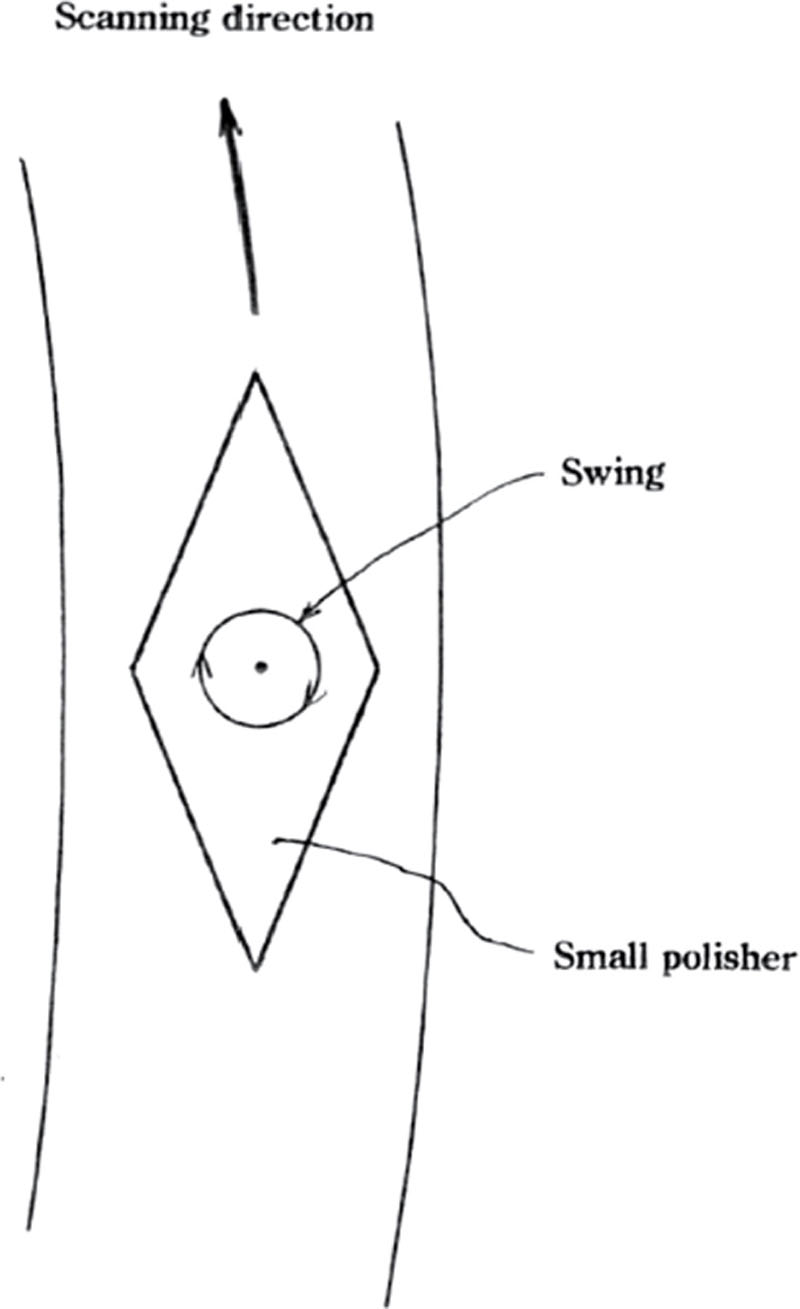
| Complex | Computer-aided polishing | Making a small polisher to travel on work surface by using computer | |
| [Using flow effect of slurry] | |||
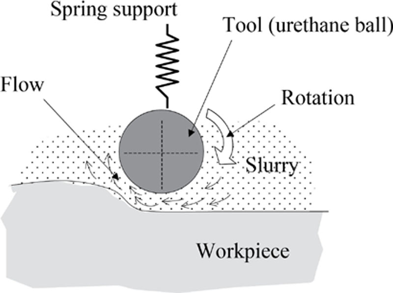
| EEM | Mild stock removing action with abrasives in hydrodynamic flow of slurry around ball tool | X-ray mirror Optical grade dies | |
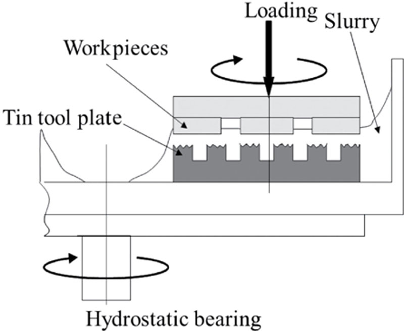
| Float polishing | Stock removing action with abrasives in hydrodynamic flow of slurry on flat polisher | Glass Plate Ferrite | |
| [Removing chemical reactive products] | |||
| Mechanochemical polishing(wet) | Growing and removing reactive products as hydration film under wet condition | Si wafer GaAs wafer | |
| Chem. | (dry) | Peeling off reactive product film with 0.01 μm SiO2 powder under dry friction condition | Sapphere Si3N4 ceramic |
| Hydration polishing | Growing hydration film under 50-200°C water vapor condition and wiping off with wood or carbon tool | Sapphere ZnSe lens | |
| [Using chemical removal] | |||
| Disk-type chamical polishing | Chemically removing with friction by using non-abrasive chemical solution and non-woven fiber sheet | GaAs wafer InP wafer | |
| Hydration polishing | Chemically removing with non-abrasive chemical solution layer between work and polisher | FdTe wafer ZnSe wafer | |
| P-MAC polishing | Chemically removing by using non-abrasive chemical solution and fluorocarbon foam polisher Working conditions change as polishing advances | ||

Improvement of Optical Polishing
Noncontact Polishing Method
6.5. Chemical compound polishing
Ultraprecision Chemical Compound Processing Methods
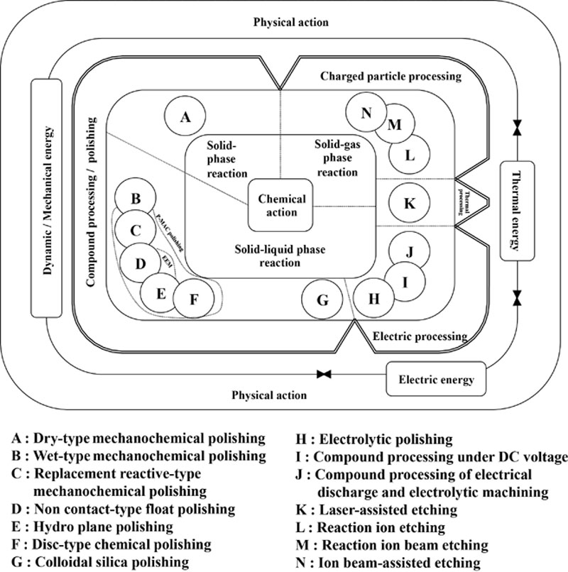
Table 6.5
Main Factors for Polishing
| Processing mechanism | Efficiency | Accuracy | Quality (low damaged layers) |
| 1. Mechanical polishing | particle dia., hardness: large (diamond, alumina, cellium, oxide, etc) pressure, relative speed: high | plate shape accuracy, system motion accuracy, particle dia. and distribution, polishier materials | opposite to what listed in “efficiency” |
| 2. Wet-type MCP/CMP | reagent (chemicals) concentration, particle density: high atmosphere temp.: high | plate shape accuracy, system motion accuracy, plate/chemicals temp. control | reagent concentration: high atmosphere temp.: high particle density: low soft abrasives/soft polisher |
| 3. Dry type mechano-chemical polishing | particle material: reactivity against workpiece (solid-phase reaction), soft abrasives | plate shape accuracy, system motion accuracy | particle dia: small particle material: reactivity against workpiece, soft abrasives |
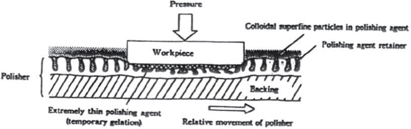
| 4. Colloidal Silica Polishing | particle density: high gelling speed, high pressure particle/workpiece: correlation, colloid chemical action | plate shape accuracy, system motion accuracy | particle density: high particle dia./ distribution: small particle/workpiece: correlation, soft particle, colloid chemical action |
| 5. Non-contact Polishing | particle dia., kinetic energy: large, number of particles: large correlation particle/workpiece: correlation | particle kinetic energy control, system motion accuracy, particle dia. and distribution | particle dia, kinetic energy: small, number of particles: large particle/workpiece: correlation |
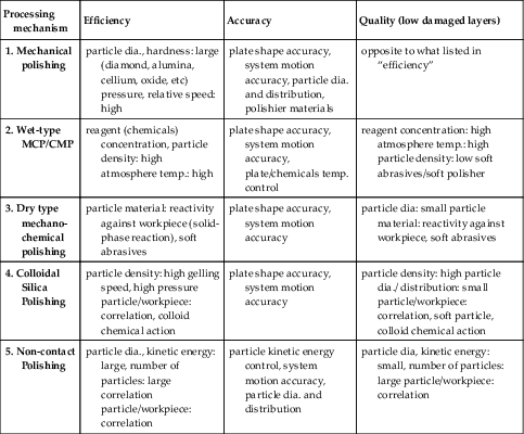
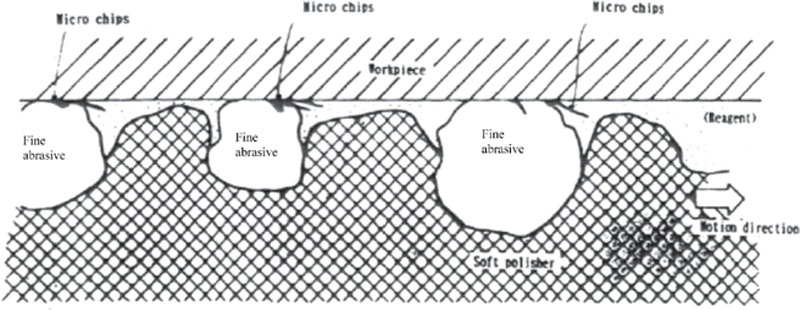
Because wet-type and dry-type mechanochemical polishing are dependent on the chemical properties of workpieces, they can only be applied to a limited range of materials. However, this polishing method can process almost all kinds of materials to a strain-free, mirror-like surface. The final result depends, however, on the hardness of workpieces, which sometimes causes degradation of processing efficiency. Other polishing methods include Si wafer processing, which combines the polishing mechanism of wet-type mechanochemical polishing with the present polishing mechanism. This polishing method will be discussed later in this chapter.
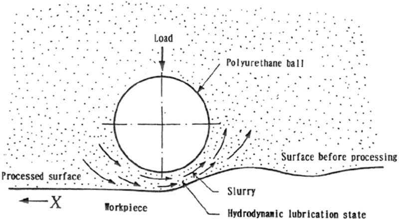
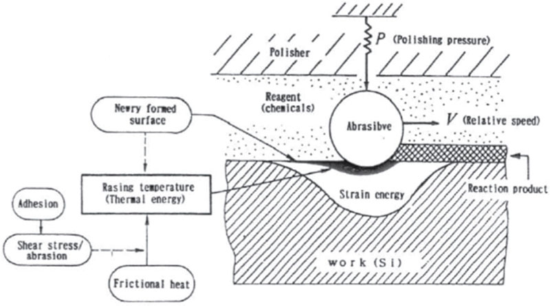
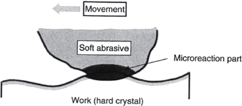
When the processing unit diminishes to the atomic or molecular order, particle surface atoms join with the workpiece surface atoms without inducing plastic behavior, followed by destruction of the joints. The polishing progresses this way. Consequently, almost no mechanical damage is left after the atoms are removed. In mechanical and mechanochemical polishing methods, abrasives retained by a polisher, in some cases, in a solution, act upon workpieces. On the other hand, EEM and EEM-applied noncontacting polishings by the collision of abrasives with workpieces accomplish high-quality and high-precision polishing.
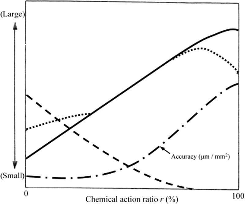
In general, processing efficiency, processing precision, and depth of damaged layers are reciprocally related. For those chemical reactions included in the processing mechanism such as mechanochemical polishing, the higher the processing efficiency, the fewer the damaged layers. However, because the processing surface precision degrades as chemical actions become large, chemical reactivity needs to be controlled in order to obtain better precision.
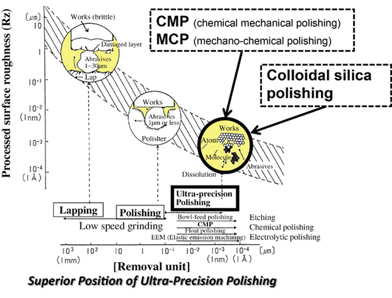
Figure 6.29 shows the general characteristics chemical compound polishing. With lapping, the efficiency increases approximately in proportion to the diameter of abrasives used; however, such a relation is not greatly noticeable when polishing with particles below 1 μm. For polishing with particles below 0.1 μm, the magnitude of the number of active particles has a large effect on efficiency. In other words, high efficiency can be achieved by increasing the processing pressure with the polisher uniformly working on the surfaces of workpieces. Because transcribing the polisher surface is a basic principle, processing precision is largely dependent on the precision of the polisher or the plate on which workpieces are mounted. However, in the case of processing methods such as EEM, which scans the area to be processed, the efficiency depends primarily upon its scanning accuracy.
Wet-Type Mechanochemical Polishing and Chemical Mechanical Polishing
Mechanochemical Polishing (MCP)/Chemical Mechanical Polishing (CMP) of Silicon Wafer for Semiconductor
Table 6.6
Polishing Conditions for Bare Silicon Wafers
| Processing conditions Porcess | Slurry (polishing agent, abrasives) | Pad (polisher, polishing pad) | Polishing pressure | Stock of removal | Target |
| First polishing | SiO2 type abrasives (colloidal silica, pH 10–11) Particle size: 50–100 nm
Polishing agent: Alkaline solution/Amine or KOH base
| Polyurethane impregnated polyester nonwoven cloth (hard type) | 30–40 kPa | 10∼15 μm (30–50 min) | -High efficiency -Smooth mirror surface (2-3 nmRz) |
| Second polishing | SiO2 type abrasives (colloidal silica, pH 10–11): Particle size: 50–80 nm
Polishing agent: Alkaline solution/Amine or KOH base
| Polyester nonwoven cloth (semihard type) | 30–35 kPa | 1–2 μm (3–5 min) | -OSF-free* -Improvement of surface roughness (1-2 nmRz) -Microscratch free |
| Third-Forth polishing | SiO2 type abrasives (colloidal silica, pH10): Particle size: 35–50 nm
Polishing agent: Amine/Ammonia solution Additive: Polymer/lubricant(ex. CMC)
| Foam polyurethane/artificial leather (soft type) | 10 kPa or less | 0.1–0.3 μm (3–5 min) | -Haze free -Contamination free -Surface roughness (1 nmRz) |

Processing Mechanism
 (6.2)
(6.2)
 (6.3)
(6.3)
MCP/CMP of Wafers for Compound Semiconductors
Based on these polishing characteristics, the processing mechanism is as follows.
This Ga(OH)3 easily dissolves in sodium hydroxide.
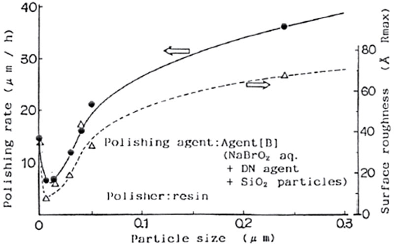
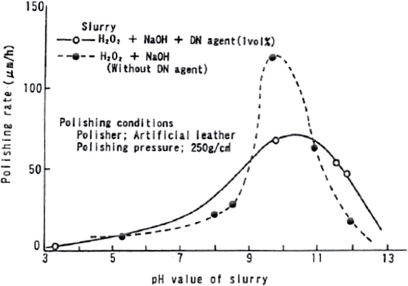
From this processing mechanism of GaAs, a slurry with an oxidant to which a small quantity of alkali hydroxide is added is basically effective for the mechanochemical polishing of GaAs crystals. Achieving high-quality surfaces by adding a DN agent with a surface penetration function allows for removal of the reaction products (films, stains) from the surfaces.
An experimental polishing of GaAs has been made using as a slurry an oxidant H2O2 with a small quantity of NaOH. Figure 6.37 is an example of the processing characteristics with a H2O2 – NaOH type solution to which a DN agent is added. Maximum removal rate is given at about pH = 10. Thus, similar removal rate and surface quality to those of NaBrO2-type solutions have been obtained. However, although SiO2 fine particles are added, the increase of the removal rate will not be as remarkable as that of NaBrO2 solution, presumably because reaction products are not formed on the surfaces as solidly as NaBrO2-type solutions.
From the processing experiments of CdTe crystals and the results of its chemical analysis, the following will be drawn as a processing mechanism to the mechanochemical polishing of CdTe crystals.
First, by creating an atmosphere that makes the CdTe surface easily oxidized by a DN agent, and finally some kind of reaction product is deposited on the surface. Then, oxide films or reaction products deposited on the surface are mechanically removed by abrasive grains or a polisher. By repeating these processes, a high-quality surface is produces.
We have discussed the processing mechanism of GaAs and CdTe crystals for compound semiconductors and drew a conclusion that its processing mechanism is basically the same as that of the mechanochemical polishing of Si crystals.
Colloidal Silica Polishing
Basic Processing Characteristics
Table 6.7
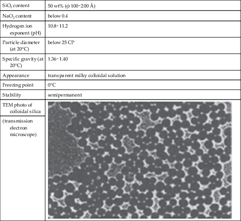
Composition of Colloidal Silica and its Characteristics (for the First Polishing)
| SiO2 content | 50 wt% (φ 100∼200 Å) |
| NaO2 content | below 0.4 |
| Hydrogen ion exponent (pH) | 10.8∼11.2 |
| Particle diameter (at 20°C) | below 25 CP |
| Specific gravity (at 20°C) | 1.36∼1.40 |
| Appearance | transparent milky colloidal solution |
| Freezing point | 0°C |
| Stability | semipermanent |
| TEM photo of colloidal silica | 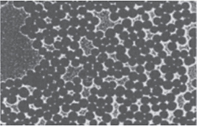 |
| (transmission electron microscope) |
 (6.9)
(6.9)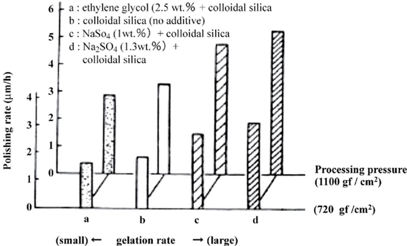
Applications to Functional Materials
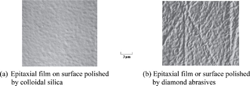
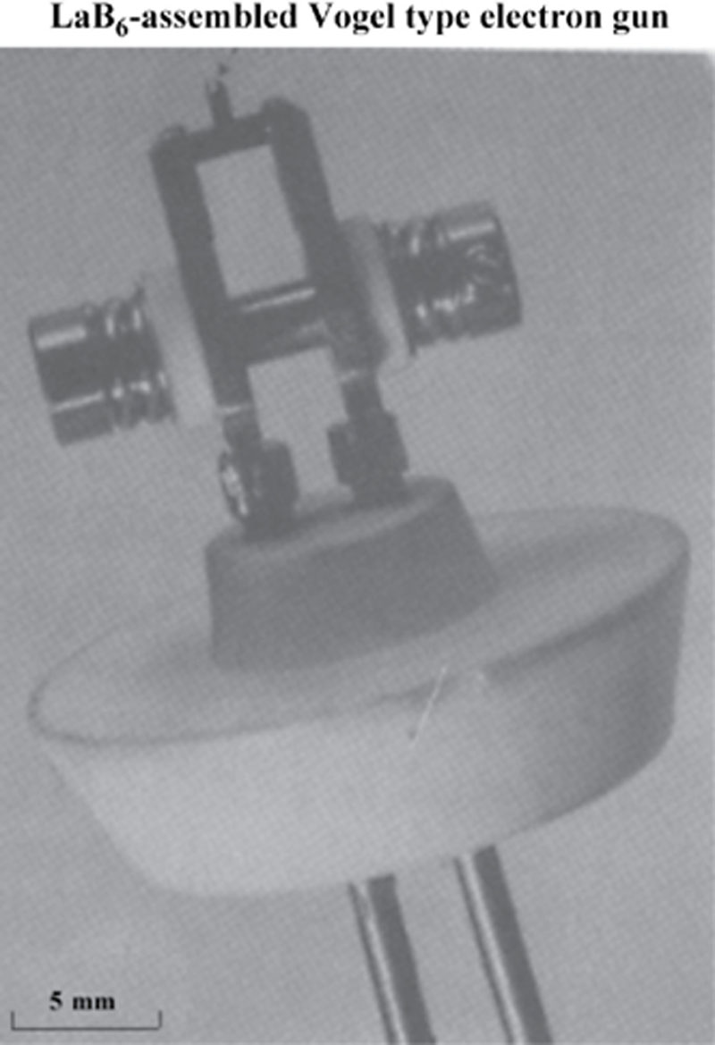
We have also investigated the processing defects of LaB6 crystal surfaces finished with colloidal silica through etching (dilute HNO3 solution); we detected no defects (like latent scratches) arising from the processing. The polished surfaces were also found to be strain-free and of high quality.
An electron gun was experimentally manufactured to apply this method (Figure 6.44); it was afterwards subjected to the evaluation of its characteristics and confirmed to have excellent electron radiation characteristics.
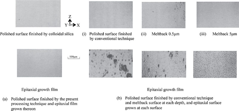
With regard to the surfaces polished using the conventional method, it has been shown that only a few micrometers etching can produce variation ![]() α according to the relationship between the depth etched by melt back and the variation amount
α according to the relationship between the depth etched by melt back and the variation amount ![]() α to the lattice constant (α = 5.153 Å) of a bulk. On the other hand, the polished surfaces with colloidal silica are capable of obtaining a strain-free (
α to the lattice constant (α = 5.153 Å) of a bulk. On the other hand, the polished surfaces with colloidal silica are capable of obtaining a strain-free (![]() α = 0) epitaxial film even without undergoing etching, proving that the surfaces polished with colloidal silica polishing are completely strain-free and without damage.
α = 0) epitaxial film even without undergoing etching, proving that the surfaces polished with colloidal silica polishing are completely strain-free and without damage.
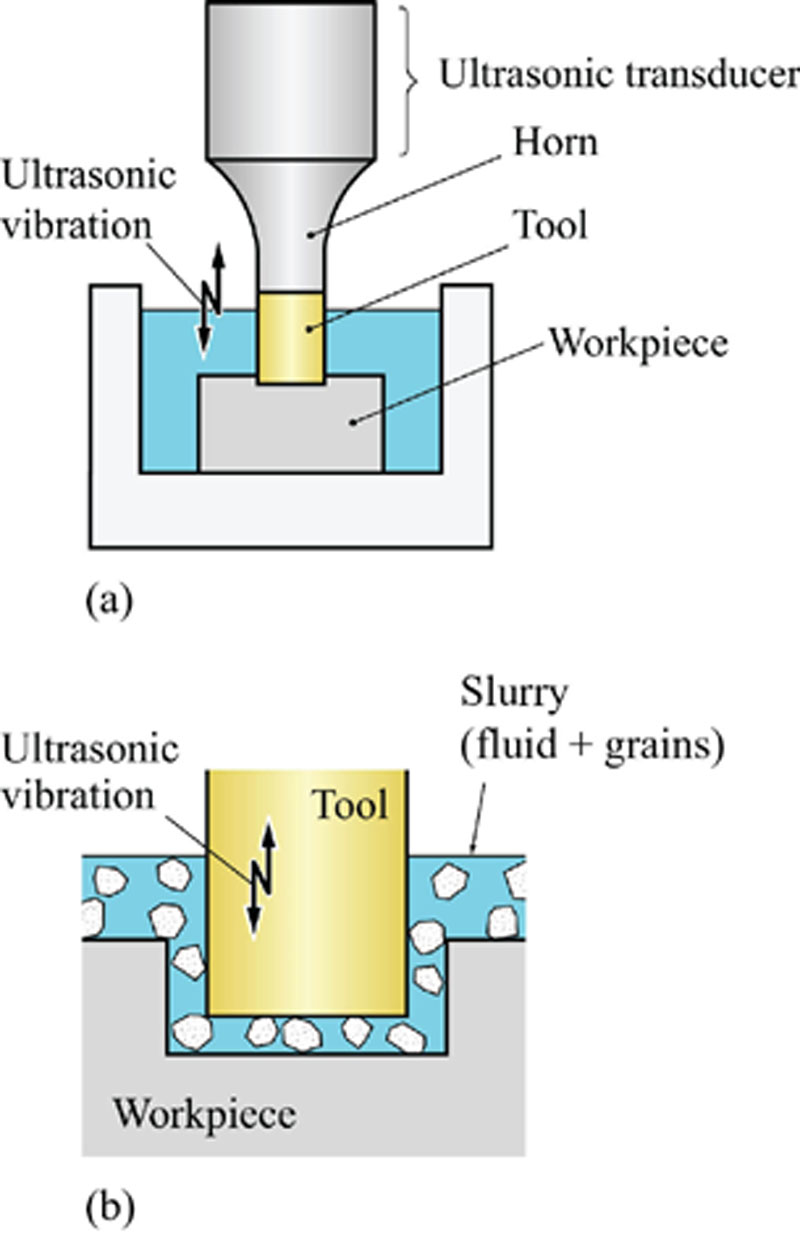
6.6. Ultrasonic Lapping
Introduction
Material Removal Mechanism in Ultrasonic Lapping
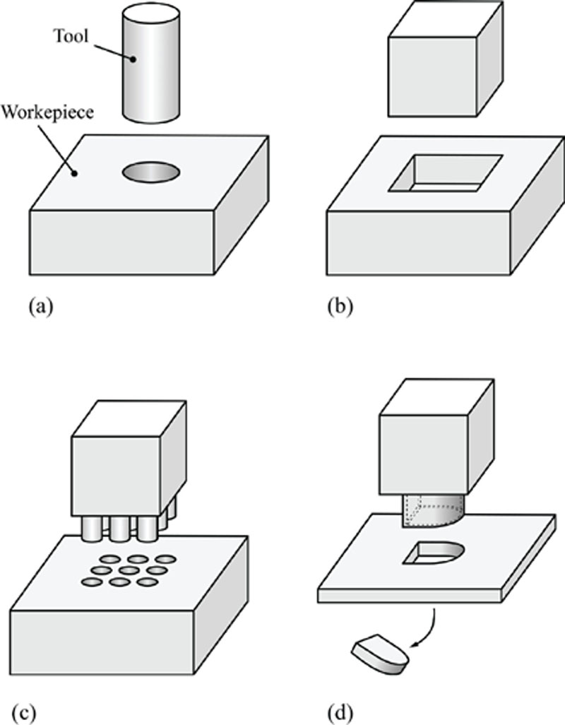
Characteristics of Ultrasonic Lapping
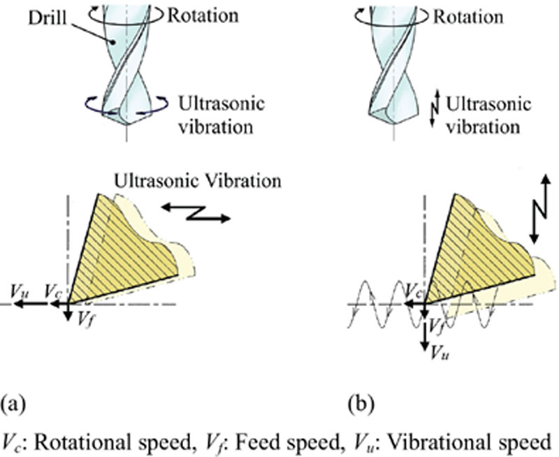
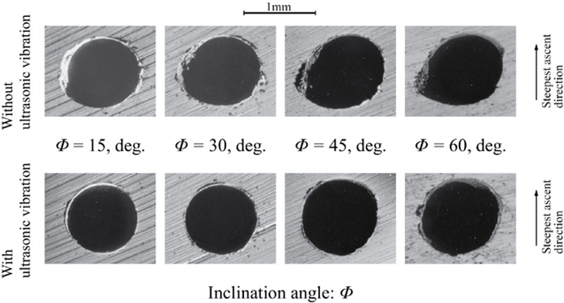
Application of Ultrasonic Vibration
6.7. Abrasive Flow Machining
Process Fundamentals
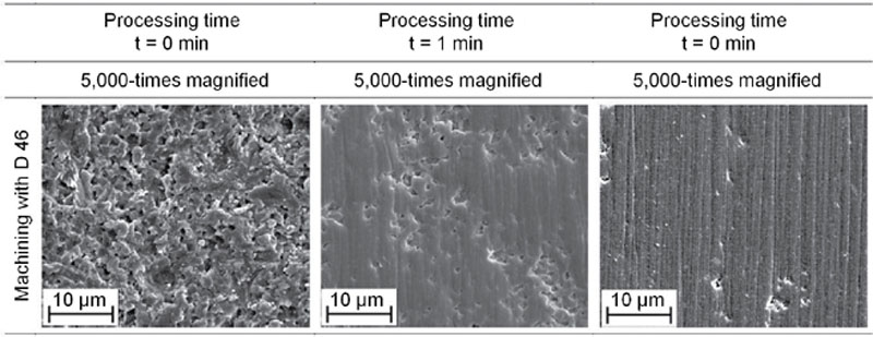
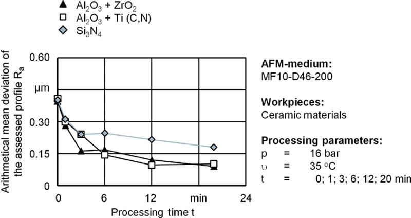
AFM of Ceramics