
Chapter 8
Grind/Lap of Ceramics with UV-Bonded Diamond Wheels
Qiuyun Huang*
Lei Guo*
Abstract
In conventional lapping process, the lapping efficiency is limited due to the abrasion mechanism that is illustrated as three-body abrasion. In order to improve the efficiency and surface finish, a fine grinding or grind/lap process is proposed and studied in this research. First of all, the material properties of the ultraviolet-curable resin and mixture are investigated and the optimum combination of resin and diamond abrasive was selected. Besides, kinematics of the grind/lap was analyzed to study its influence on the performance of the resin bonded wheel. Moreover, based on experimental results analysis, the mechanism for grind/lap process was proposed, and it is considered as a combination of conventional grinding and lapping process. At last, two ways to improve the performance of wheel were carried out and the results were compared.
Keywords
Ultraviolet curable resin
kinematics of fine grinding
grind/lap
8.1. Introduction
Abrasive processes have been employed in industry manufacture for more than a century and the origin could be traced back to Neolithic times. Grinding, lapping, and polishing were significantly developed in twentieth century, and the application of machining technology for achieving high quality and efficiency increased rapidly. Compared to grinding, lapping and polishing are similar processes by which fine surface finish, high-dimensional accuracy, flatness, and minimal subsurface damage can be obtained. These techniques have been used in the optical lens, semiconductor, and electronics industry on a wide range of material from silicon, glass, and ceramic to metal and their alloys. Lapping, as one of the most important techniques in surface finishing, has become more and more important in the ceramic industry [1].
The traditional lapping procedure is based on a slurry process, and the abrasive grains are freely moved in the process. The major problem for conventional a lapping process is to get a uniform slurry distribution between the lapping pad and the workpiece. During the lapping process, the lapping pad becomes smoother and the pores fill with chips and pad material. Transportation of the slurry to and debris from the workpiece surface will be weakened, which is called glazing phenomenon. As a result, the material removal rate and machining efficiency will drop. In addition, slurry handling and disposal is problem that should be considered for conventional lapping [2].
With huge development and remarkable progress in material science, the modern machining technology needs to achieve high quality and efficiency. Therefore, a new lapping process called fixed-abrasive lapping appeared recently [3]. Fixed-abrasive lapping, also known as fine grinding or grind/lap, was first proposed by Gatzen [4]. Subsequently, in research by Choi and colleagues, thermocurable fixed-abrasive pad processes were used to achieve a submicron-level surface roughness [5]. Tomita and colleagues studied development of new bonding materials for fixed abrasives of grinding stone and proposed a new process by using a double-side lapping machine with a grinding stone [6].
Recently, researchers investigated the use of ultraviolet-curable resin in fabrication of abrasive tools. Since 1968, when a German made the ultraviolet-curable resin commercialized for the first time [7], ultraviolet-cured rapid prototyping technology has developed quickly and become one of the most advanced techniques in the manufacturing industry. Tanaka and colleagues proposed a method to develop a grinding wheel with cured resin, while others studied different abrasive tools using ultraviolet-curable resin [8–11].
8.2. UV bonding techniques
UV Curable Resin
The UV curing technology used in manufacturing can be traced back to the early 1950s. American engineers applied the technology of light solidifying to make a typography board with UV-curing resin. In the past 20 years, researchers have developed photo-manufacturing technology in various applications, and with the application of UV-curing resin in the fields of rapid prototyping, molding material, medical treatment, and micro manufacturing. Various kinds of UV-curing resins with different features have been developed.
In this research, two types of UV-curable resins and their mixtures will be evaluated according to the mechanical properties of the abrasive tool. The first type of adhesive is an epoxy-based material. While some people use the term epoxy generically to refer to all high-performance engineering resins, epoxy has a quite specific meaning within the adhesive world. The second is an acrylic-based UV-curable resin that we will exam because it differs from epoxy-based resins.
Epoxy resin is one of the stiffest plastic materials. In the UV-curing process, epoxy resins use a catalytic curing mechanism. The catalyst is a by-product from the reaction of the photoinitiator to UV light. One consequence of this is that UV-curing epoxy resins exhibit a special capability. Material that is not directly exposed to UV light will cure eventually, which may be promising for the uncompleted curing problem concerned with the abrasive’s resistance to UV light. Another advantage to using epoxy-based resins is they are easily modified by mixing them with different additives, which may create great potential for meeting the special needs of abrasive tool making.
Acrylic resin, the most wildly used UV-curable resin, results from an entirely different chemistry and a different type of photoinitiator than epoxies. Curing of acrylic resins is a free radical mechanism. The free radicals are produced by the photoinitiator when it is exposed to ultraviolet light. However, the free radicals are consumed in the adhesive curing process, so acrylic resins can only cure where UV light is delivered. At least one of the components being bonded must be UV-transparent to some degree. Modification of properties in acrylic resins is more often conducted at the chemical level, through changes in formulation or combination with other base resins. A wide range of properties can be utilized, including impact resistance, surface insensitivity, environmental resistance, and others.
In fact, few kinds of pure UV-curable resins are used as bonding agents because high-composite characteristics are required. However, the theory of composite material indicates that it is possible to develop such materials.
The early stage of rapid prototyping technology is mostly used to manufacture prototypes for the quick verification of designs or prototypes with a low range of functionality. These prototypes give a first impression of a part’s properties. Fully functional prototypes with the whole range of a part’s properties cannot be built with the UV-curing process because of its limited material properties. However, many opportunities to reinforce resins exist, one of which is to fill the resin with powders such as ceramics, which shows great promise. Research has shown that different powder-filled UV-curable resins can theoretically be used to manufacture highly loadable parts and tools. In general, the stiffness, wearing resistance, and thermal and chemical resistance of the composite are higher than those of the pure resin.
Mechanism of UV Bonding
Two components are present in the UV-curing resin. One is the basic oligomer and the other is the photoinitiator. The key characteristic of the photoinitiator is that it will not react with the resin by itself; the photoinitiator must absorb ultraviolet light before anything can happen (i.e. change of physical properties). When the UV light is delivered, the photoinitiator will undergo a chemical reaction and produce some by-products that cause the adhesive to harden. Figure 8.1 shows the principle of the reaction.
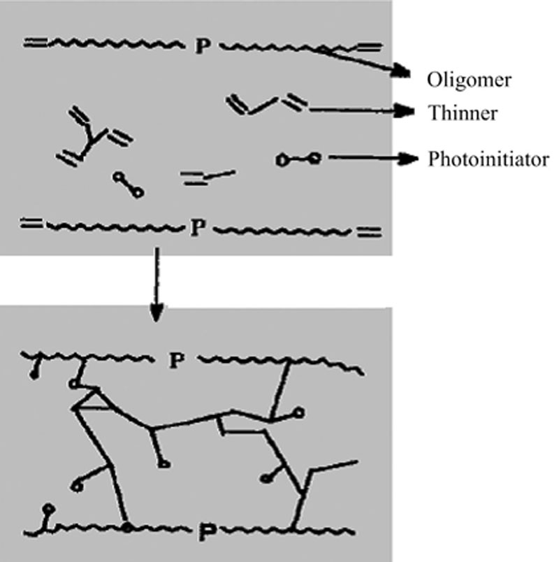
Figure 8.1 Reaction of UV curing process.
For the photoinitiator to react correctly, it must be exposed to light of the correct wavelength and of sufficient intensity. Otherwise, the chemical reaction will not happen, or it may not happen completely, resulting in poor or inconsistent adhesive performance. Compared with the thermosetting resin, this chemical reaction converts the resin from a liquid to a solid as a result of an increase in molecular weight, without the volatilizing. From this principle, the use of UV-curing resin has many benefits to product manufacturers.
1. Short process of solidifying: It needs only a few seconds or minutes to finish the process of solidifying.
2. Process consistency and flexibility without large field and equipment.
3. Reduced environmental considerations: Almost no organic dissolvent results from the use of UV-curing resin.
4. Less energy consumed: In comparison to the heat-solidifying process, this process could save about 90% of energy.
These advantages suggest that in the near future UV-curing resin will replace thermosetting resin and become the new bonding agent in the manufacture of thinner oligomer abrasive tools.
Mechanical Bonding
The bonding strength of abrasives is related to the efficiency of cutting tools and life of abrasive tools. The bonding mechanism of the UV-curing process is different from the conventional thermoset process, and many theories have been developed to explain the process of bonding in adhesive structures. Individually, each of these theories is inadequate to describe the complete process of bonding in most situations. However, each theory contributes an understanding of the overall process of bonding and, therefore, is important. Figure 8.2 illustrates the five predominant mechanisms of adhesion.
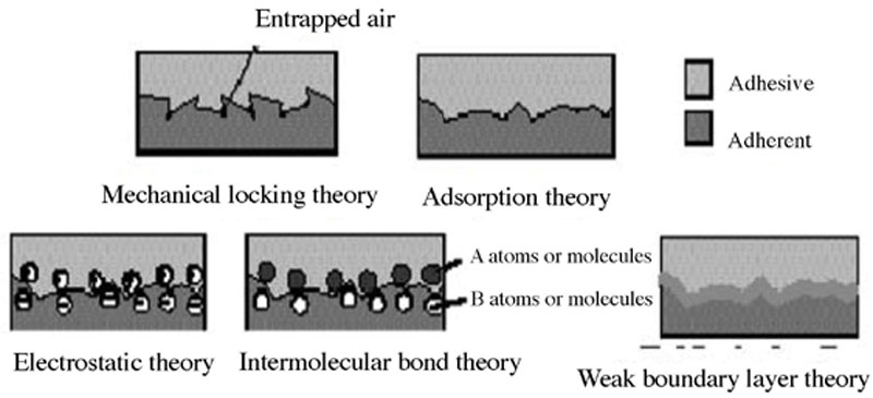
Figure 8.2 Adhesion mechanisms.
According to the mechanical bonding theory, in order to work well, an adhesive must fill the surface valleys of abrasives to be bonded, as well as displace trapped air. Adhesion is the mechanical interlocking of the adhesive and the abrasives, and the overall strength of the bond is dependent upon the quality of this interlocking interface. To this end, a rough-surfaced abrasive is highly recommended for optimum bonding. If the surface of the abrasive, in most cases diamond, is too slippery for better bonding, a preprocess will be considered. Coating is one preprocess to be used in this research, not only for its rough surface but also for forming a chemically reactive surface. The significant effect of the coating was reported. Figure 8.3 shows the diamond coated with nickel suited to epoxy adhesive – a key point to study for bonding strength.
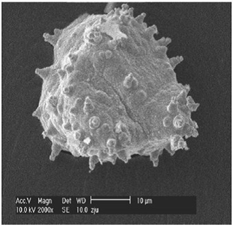
Figure 8.3 Nickel-coated diamond abrasive.
Adsorption Bonding
The adsorption mechanism theory suggests that bonding is the process of intermolecular attraction (van der Waals bonding or permanent dipole, for example) between the adhesive and the diamond at the interface. According to this theory, an important factor in the strength of the bond is the soakage of the diamond by the adhesive. Soakage is the process in which a liquid spreads onto a solid surface and is controlled by the surface energy of the liquid–solid interface versus the liquid–vapor and the solid–vapor interfaces. In the proposed research, in a practical sense, to soak the diamond surface, the adhesive should have a lower surface tension than the diamond.
8.3. Manufacturing of UV-bonded diamond wheel
Properties of UV-Curable Resin
Basic properties of a potential bonding agent for manufacturing of abrasive tools are, first, the mechanical characteristics, such as tensile strength, hardness, and wearing resistance. Second are the processing abilities, such as the curing depth and shrinkage during the UV-curing process. The final are the adhering abilities to abrasives and other additives, such as a variety of fibers and microparticles used to reinforce the material or modify the special properties.
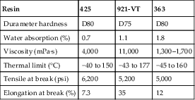
The technical specifications for three different ultraviolet-cured resins selected in this research – the 921-V and 425 resins purchased from DYMAX Corporation and the HTU-363 from HUITIAN Company – are listed in Table 8.1. The ultraviolet resin can be cured by ultraviolet light and has certain hardness, strength, and other basic mechanical or chemical properties. For the bonding material in lapping plate, it must meet some requirements to be used, so the hardness, porosity, and tensile strength tests were carried out to select the appropriate one.
Table 8.1
Three Ultraviolet-Cure Resins
| Resin | 425 | 921-VT | 363 |
| Durameter hardness | D80 | D75 | D80 |
| Water absorption (%) | 0.7 | 1.1 | 1.8 |
| Viscosity (mPa·s) | 4,000 | 11,000 | 1,300–1,700 |
| Thermal limit (°C) | −40 to 150 | −43 to 177 | −45 to 160 |
| Tensile at break (psi) | 6,200 | 5,200 | 5,000 |
| Elongation at break (%) | 7.3 | 35 | 12 |
Properties of Diamond Abrasive
As the hardest abrasive in the industry, diamond is preferred in the lapping process. In this process, a fine surface finish and higher material removal rate can be achieved. In modern industrial manufacturing, two kinds of diamond abrasive grains are primarily used: the metal bond diamond powder and the resin bond diamond powder. The metal bond diamond powder (MA) is monocrystalline micron and nanometer-size diamond that exhibits a 3-D blocky particle shape. It provides an aggressive stock removal and superior surface finish properties. The resin bond diamond powder (RA) is monocrystalline diamond that exhibits typical sharp friable-resin bond crystals, micronized from selected industrial grade powders. The particle size distribution of MA and RA grains are around 10–20 μm. Both of the RA and MA abrasive powder are purchased from Engis Company, and for the initial experiment in our research, RA and MA abrasive particle will mixed with different types of UV resin to find out the best combination.
In addition, surface-treated MA abrasive is introduced later for the manufacturing of the lapping plate. The same as the normal MA abrasive, surface-treated MA has a size distribution of 12–22 μm. Comparisons are shown in Figures 8.4 and 8.5 gives a SEM of those two particles. The particle size distribution of the abrasive particles is shown in Figure 8.6.
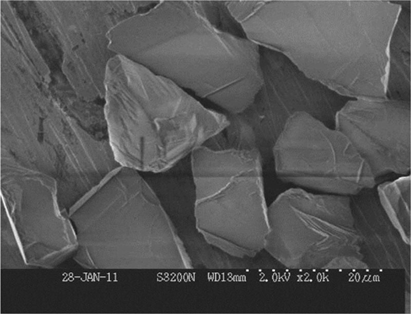
Figure 8.4 SEM image of normal MA abrasive (11288).
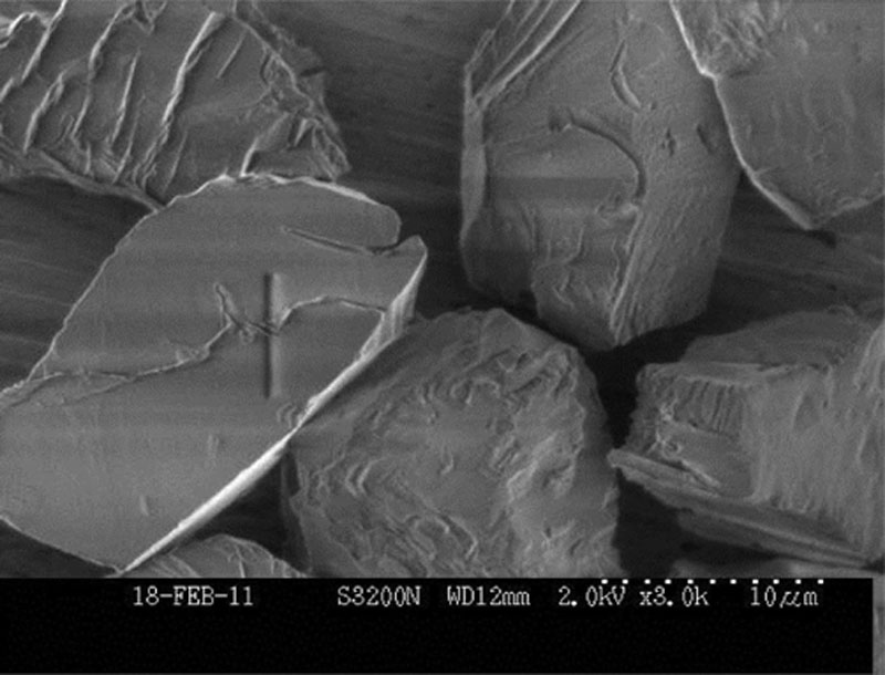
Figure 8.5 SEM image of surface-treated MA abrasive (R0206).
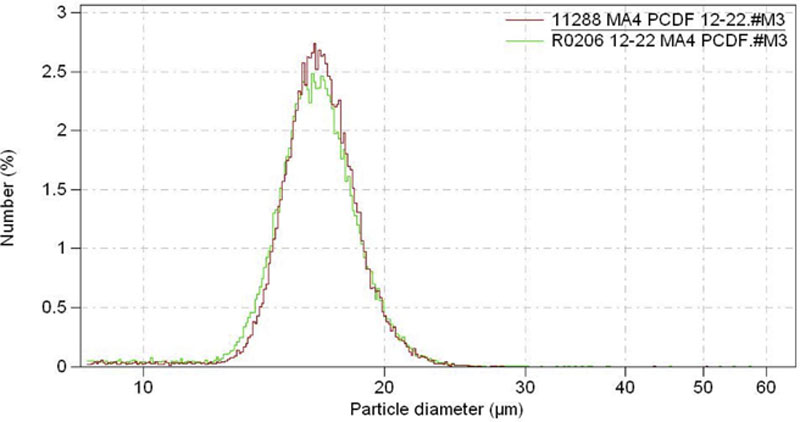
Figure 8.6 Particle size distributions of the abrasive particles.
Properties of UV-Bonded Sample
Before we build the lapping plate, basic properties of the mixture of UV resin and diamond abrasive particles, including tensile strength, hardness, and wear resistance, should be studied.
Tensile Strength
Tensile test, as known as tension test, is a basic material science test in which a sample is applied to uniaxial tension until failure. The results from the tensile test mainly consist of two curves: the tensile stress versus tensile strain and the maximum load versus maximum elongation. Moreover, Young’s modulus, Poisson ratio, and yield strength can be obtained by the test. All of these parameters determine the mechanical properties of the material, and these data are always used to select material for different purpose. In our research, three types of UV resin and two types of diamond abrasive combined together to make the samples used in tensile test.
The abrasive concentration selected for the sample is 25%. The abrasive concentration for abrasive tools is a key factor that affects the tool’s performance. For the diamond concentration of a diamond tool, it means the weight of the diamond in each cubic centimeter of the diamond tool’s working layer. The international standard has prescribed that if each cubic centimeter contains 0.88 g superabrasives, its concentration is 100%. Each increase or decrease of 0.22 g will change the concentration by 25% correspondingly [12]. In lapping and such precision machining processes, a lower abrasive concentration is used frequently.
In Figure 8.7, steel pattern is designed to make the samples used in the tensile test. Both the pure resin samples and the abrasive–resin mixture samples are prepared for the experiment. The UV resin and diamond abrasive particles are first mixed together, and then the mixture is stirred for several hours to ensure the uniform distribution of the particles. The mixture will be left overnight to improve the polymerization and remove any internal bubbles [13].
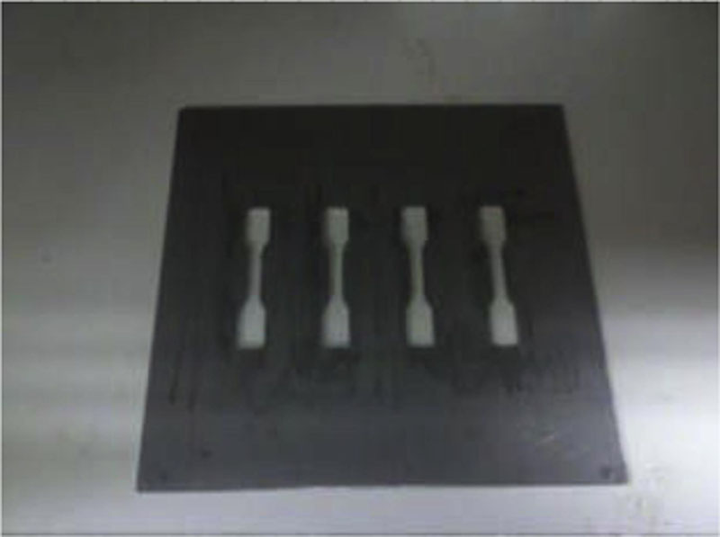
Figure 8.7 Curing pattern designed for tensile test.
The tensile stress and tensile strain curve of the six combinations are shown in Figure 8.8. No matter what kind of abrasive diamond is added to 425 resins, the mixture shows an outstanding performance on maximum tensile stress, which means they can afford more load than others. 921t UV resin mixture breaks at 20 and 30 Mpa, and it shows the weakness of the mechanical properties. For the HTU363 resin mixture, the maximum elongation is greater than the others. The elongation or tensile strain can be viewed as the representation of material elasticity, which shows the deformation takes place when force is loaded. As a bonding material in lapping plate, the deformation of the plate will embed the abrasive particle into the material and transform three-body abrasion to two-body abrasion. Sometimes this phenomenon helps the lapping process in material removal rate and surface finish. However, if the material is too soft, the lapping plate will have difficulty holding the particles, and then greater amounts of edges on the abrasives would be submerged. Thus the machining efficiency could be influenced.
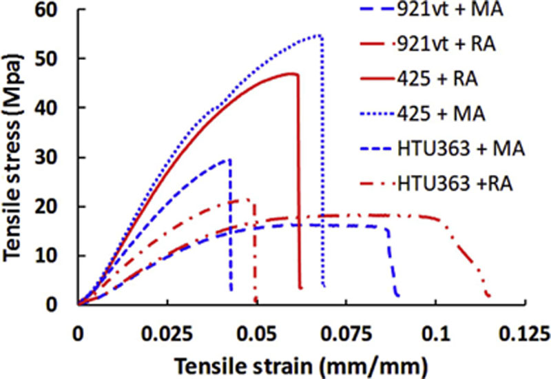
Figure 8.8 Tensile stress vs. tensile strain of abrasive–resin mixture.
Porosity
The lapping plate made by resin remains porous, not only in UV-curable resin bonding material but also in thermocurable resin, because it is a material property of resin itself.
Previous studies investigated whether lapping efficiency is significantly affected by porosity. The porosity can change the hydrodynamic performance between the lapping plate and the workpiece, as well as provide space for grains, chipping, and lapping fluid during lapping process.
Microscopies of each resin are carried out in Figures 8.9–8.11. Different size and density can be found in different resins; the desultorily distribution of these pores contribute to the fluid permeating on the plate.
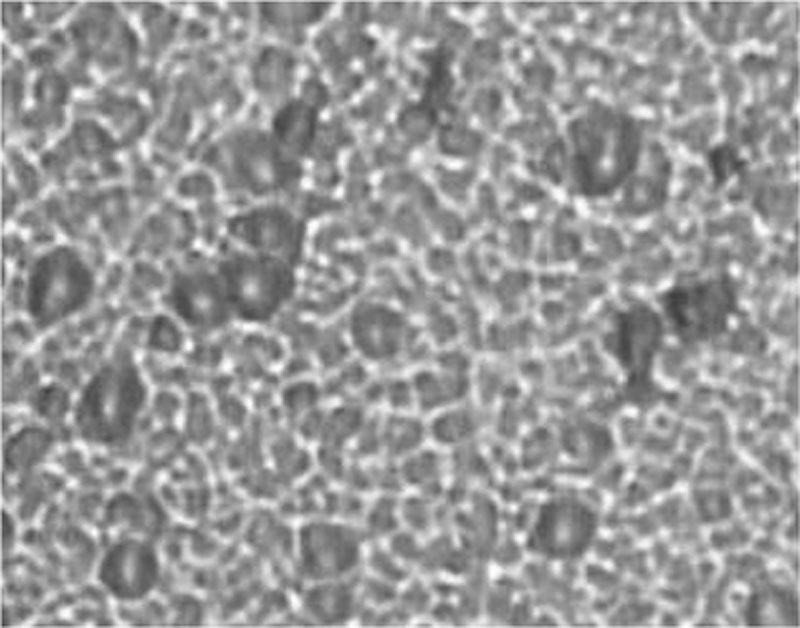
Figure 8.9 Microscopy of 921vt resin.
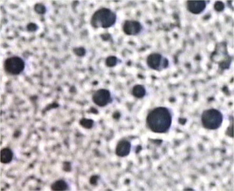
Figure 8.10 Microscopy of 425 resin.
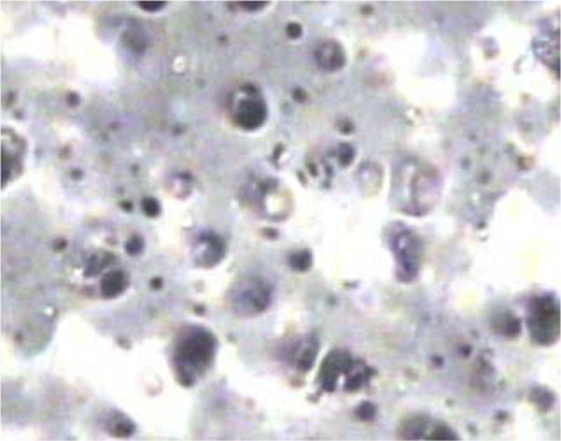
Figure 8.11 Microscopy of HTU363 resin.
Hardness and Wear Resistance
The hardness of the lapping plate is one of the key factors because the lapping plate undergoes load and produces deformation during the lapping process. The certain hardness of the lapping plate may keep the grain in the situation of scraping or rolling and thereby affect the material removal rate and surface roughness of the workpiece.
The hardness of three kinds of resin filled with two different diamond powders was tested. Furthermore their wearing properties were compared by lapping those samples under the same conditions and measuring the sample’s thickness loss. Samples are made with the pattern shown in Figure 8.12. With the blue plastic pattern, Φ18 mm samples made of different ultraviolet-cured resin were prepared.
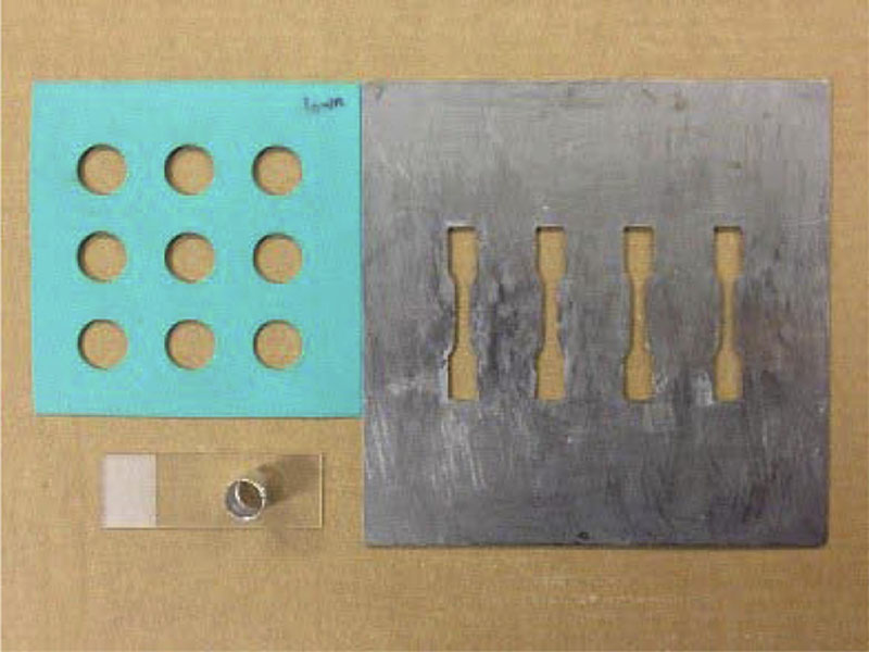
Figure 8.12 Curing patterns for different test.
The Vickers hardness of the cured samples was tested by Clark micro hardness tester CM-400AT. In order to determine the wear resistance of each combination, the samples were lapped under the same conditions. The results are listed in Table 8.2.
Table 8.2
Hardness and Abrasion of Resin-Abrasive Mixtures
| Resin | UV-resin (921) | UV-resin (425) | UV-resin (363) | |||
| Diamond powder (15 μm) | MA4 12.5%vol | RA 12.5%vol | MA4 12.5%vol | RA 12.5%vol | MA4 12.5%vol | RA 12.5%vol |
| Hardness (kgf/mm2) | 11.1 | 12.3 | 15.4 | 13.6 | 8.3 | 7.7 |
| Abrasion (mm) | 0.074 | 0.082 | 0.078 | 0.077 | 0.038 | 0.052 |

Manufacturing Process
Ultraviolet Curing System
Ultraviolet curing systems mainly consist of an ultraviolet lamp and a power supply. They are used to transform the resin from liquid to solid. In Figure 8.13, the system shown is used to test small samples for tensile, hardness, and wear abrasion. UV light is an electromagnetic wave of 100–380 nm, longer than that of X-rays but shorter than visible rays. The required wavelength for cure is specific to the resin chemistry. The wavelength distribution of Dymax is about 300–450 nm as shown in Figure 8.14.
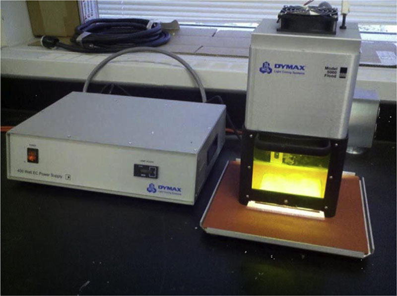
Figure 8.13 Dymax 5000 flood ultraviolet curing system.
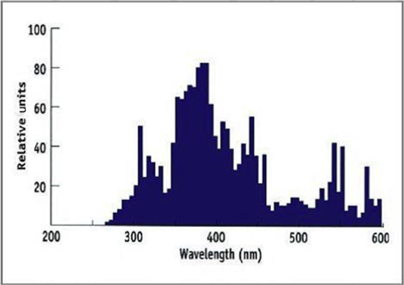
Figure 8.14 Wavelength distribution of a Dymax 5000 curing system.
UV-100 curing systems come with a large lamp (Figure 8.15) that covers a large area with UV lights. Thus, its more uniform energy distribution is more suitable for curing large samples. The working zone is based on a rotating belt with 10 speeds, and the system has three power levels (125, 200, and 300 W/in.).
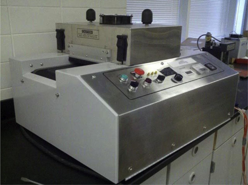
Figure 8.15 Ultraviolet lamp of UV-100 curing system.
Spin-Curing Method
Small sample pieces of resin–abrasive mixture are easy to make because the small area is easy to control and ultraviolet energy distribution is more uniform. For a large area of resin–abrasive mixture that needs to be cured, the curing process is much more complicated. A spin-coating method is proposed in previous studies, and the idea is illustrated in Figure 8.16.
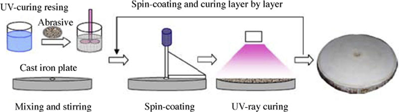
Figure 8.16 Spin-coating method.
In a spin-coating process, the resin mixture is spread on the cast iron plate and cured at one time. Although it seems like this method would reduce curing time and generate a uniform distribution of the mixture, two mainly problems arise during the process; First, a great deal of heat is generated on the surface of the mixture film within the curing process, and the uneven distribution of the heat absorption causes deformation of the surface, resulting in surface waviness. The waviness of the whole plate is difficult to deal with before lapping has taken place. Second, it is impossible for the ultraviolet lamp to produce uniform energy distribution due to the large surface area of the plate. The distance from the UV lamp to the center of the plate is different from the distance from UV lamp to the periphery area of the plate; therefore, the cure depth can vary in one plate. Besides these two problems, whether the contact area of the resin–abrasive mixture and the cast iron plate is cured remains uncertain. Even if it is cured, whether the adhesive force is strong enough to handle the lapping process is still a problem.
Slice-Curing Method
In this experiment, another curing method to build a lapping plate with resin–abrasive mixture is introduced. The plate is divided evenly into 12 slices, with the size of each slice suitable for mounting in the curing system to obtain a uniform energy distribution from the UV light. Figure 8.17 shows the steel pattern used for curing slices of lapping plate
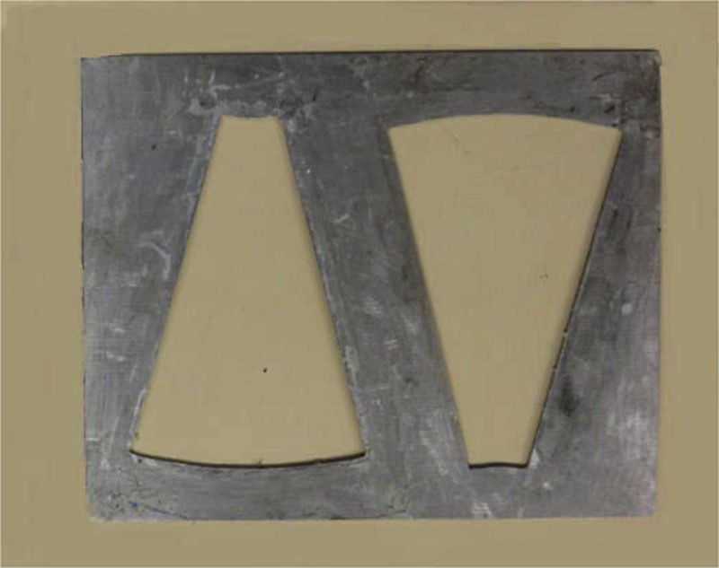
Figure 8.17 Curing pattern designed for slice of lapping plate.
The cured pieces are then agglutinated together on the cast iron plate as shown in Figure 8.18. The finished lapping plate consists of 12 slices. Because the agglutinating process is done by hand, it is difficult to keep the adhesive film thickness exactly the same, and a dressing process is necessary before the plate is used for the lapping experiment (Figure 8.19). A grinding wheel is applied to the face of the plate to ensure its flatness. This process also can be done with a conditioning ring and slurry, based on a conventional lapping process. However, the efficiency of grinding is preferable to lapping.
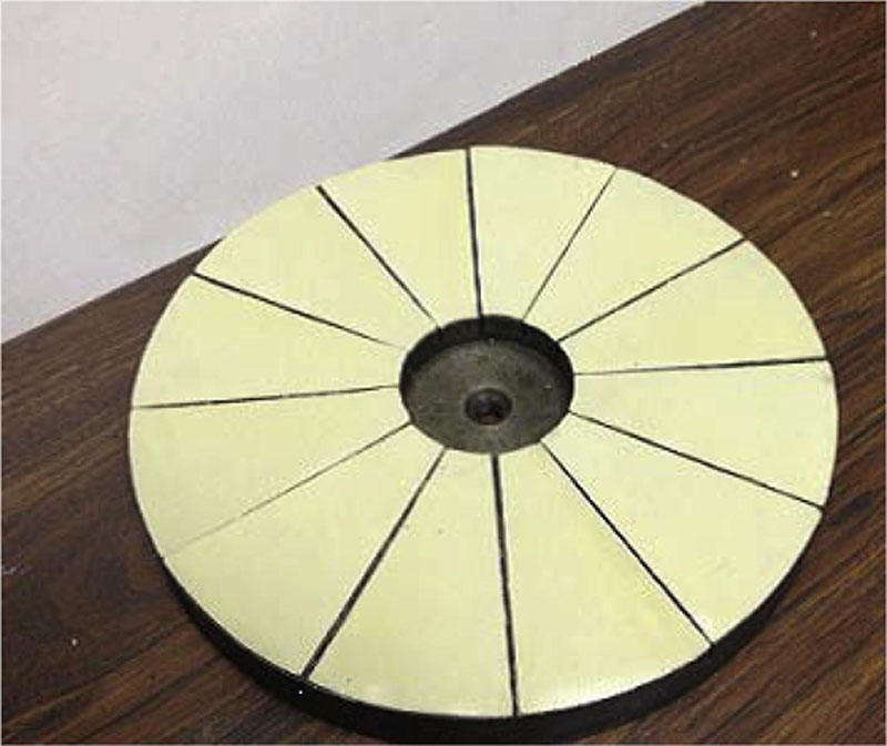
Figure 8.18 12 slices of plate.
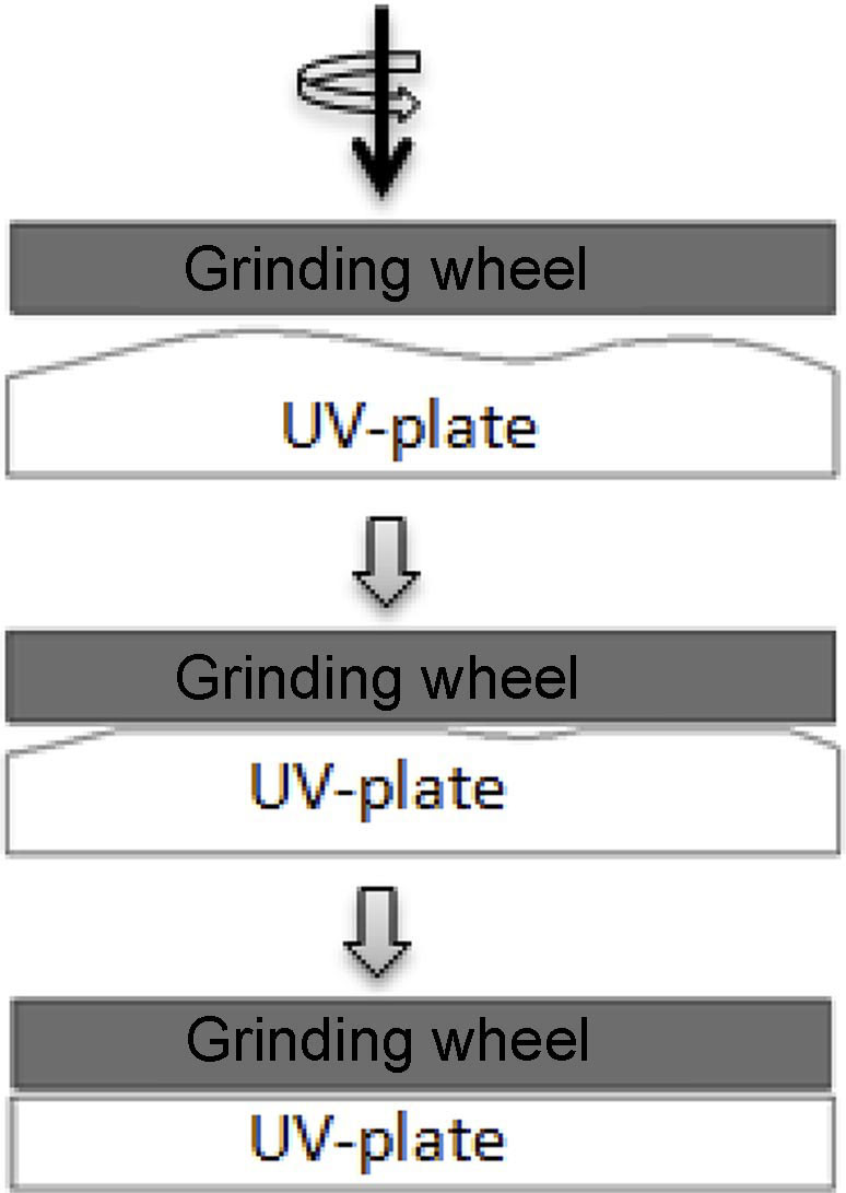
Figure 8.19 Dressing process of lapping plate.
8.4. Kinematic analysis of grind/lap
Analysis of Kinematic Path Type Under Different Lapping Coefficient N
The lapping coefficient N is given for several values to depict the relative motions between the lapping plate and workpiece holder. It represents the ratio of revolutions of the workpiece carrier holder to the revolutions of the lapping plate. In the process, the workpiece holder rotates not only around its own center in w2, but also around the lapping plate center at a speed equal to the rotation speed of the lapping plate, w1. A simplified description of the lapping coefficient N is:
 (8.1)
(8.1)where w1 is the rotational speed of the lapping plate and w2 is the rotational speed of the workpiece carrier holder.
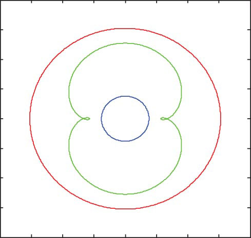
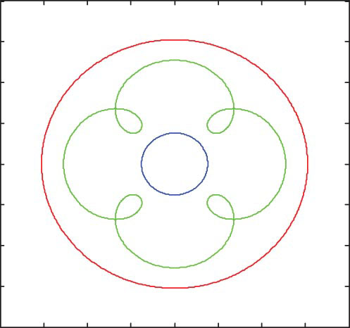
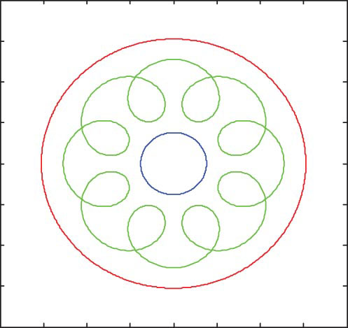
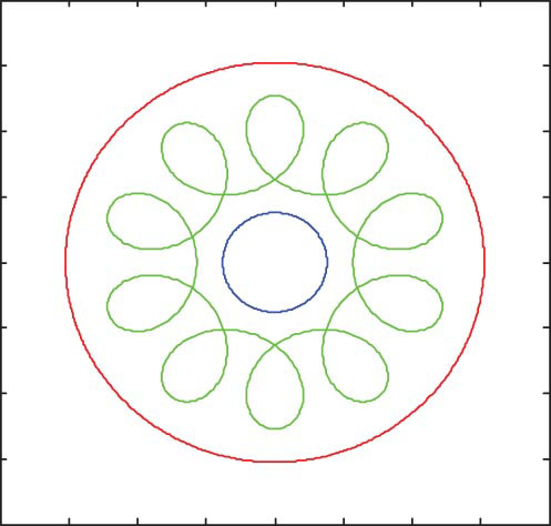
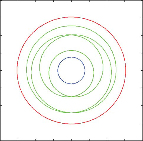
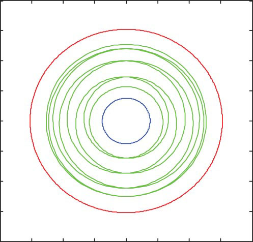
The characteristic path types that a workpiece center point covers as a function of the rotational speed ratio N are investigated in both the same and opposite directions as that of the lapping plate.
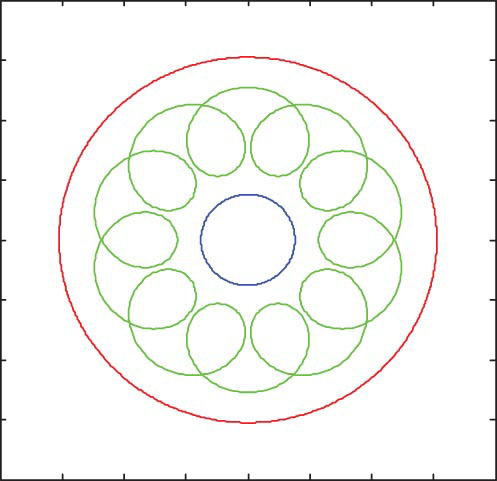
Table 8.3 shows the characteristic path types when the absolute value of N is larger than 1. Negative means the revolutions of workpiece holder and the lapping plate are in different directions. This table indicates that the kinematic types of the workpiece differ from the relative rotation speed ratio between the workpiece holder and the lapping plate. Two conclusions can be made based on the traces obtained according to Table 8.3:
1. The trace produced by a single grain is epicycloid when the rotation speed ration of the workpiece carrier holder moving relative to the lapping plate is negative; otherwise, the trace is hypocycloid.
2. When the ratio increases to a certain value, the epicycloid trace becomes interlaced epicycloids while the hypocycloid trace transitions into interlaced hypocycloid, and as a ratio gets larger, the trace displays denser conditions.
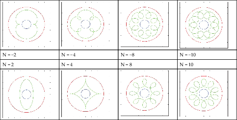
Table 8.3
Kinematical Trace of Workpiece When w2 > w1
 |  |  |  |
| N = −2 | N = −4 | N = −8 | N = −10 |
| N = 2 | N = 4 | N = 8 | N = 10 |
 |  |  |  |
When the rotational speed of the lapping plate is greater than that of the workpiece holder, the lapping coefficient is changed:
 (8.2)
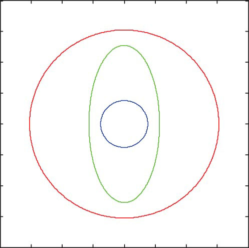
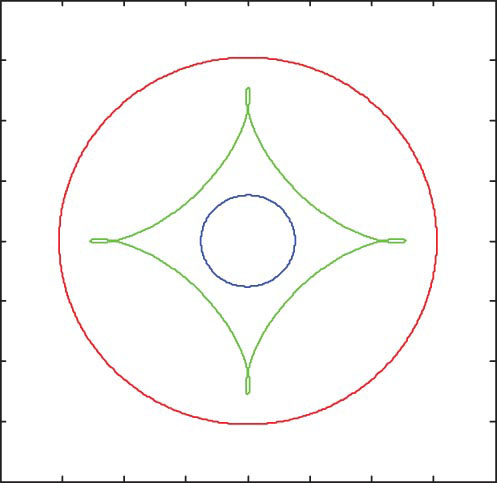
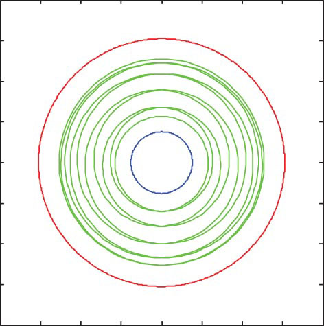
(8.2)Similar to Table 8.3, Table 8.4 shows the characteristic path types when the absolute value of N is less than 1. In such case, the trace produced by a single workpiece indicates the following:
1. The trace type of workpiece is a stretched epicycloid when the two components rotate in the same or opposite direction.
2. The traces in the two states become denser as the ratio gets smaller.
Table 8.4
Kinematical Trace of Workpiece when w1 > w2
 |  |  |  |
| N = −2 | N = −4 | N = −8 | N = −10 |
| N = 2 | N = 4 | N = 8 | N = 10 |
 | 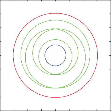 | 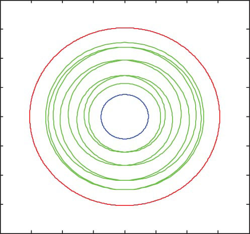 |  |

A common phenomenon can be seen from these two situations: when the ratio is larger than 1, the number of intercepts between the trace and the outer circle or between the trace and the inner circle equals the rotation speed ratio, otherwise, the intercept number equals the absolute value of the ratio minus one.
Kinematic Relation of UV Diamond Wheel and Lapping Machine
Based on the kinematic types discussed previously, the trace of workpiece on the face grinding process on a lapping machine was studied to indicate its influence on the abrasive tool and, hence, on the industrial machining.
The lapping machine used in this project was Lapmaster 12 (see Figure 8.20). The rotational speed of the lapping plate can be set with several values. Revolutions of the workpiece holder without or with different pressures are obtained versus certain speeds of lapping plate, and their relationships can be seen in Figure 8.21.
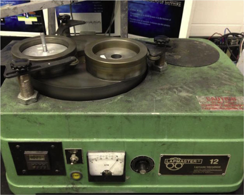
Figure 8.20 Lapmaster 12.
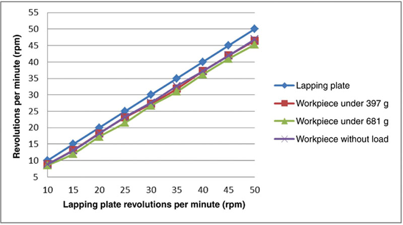
Figure 8.21 Revolutions of workpiece under different pressures.
Figure 8.21 states that the revolution of workpiece holder is less than that of the lapping plate, no matter how much it increases. The difference between the plate and the workpiece holder increases with the speed of lapping plate. It illustrates that the kinematic trace of the workpiece should be analyzed using equation (8.2).
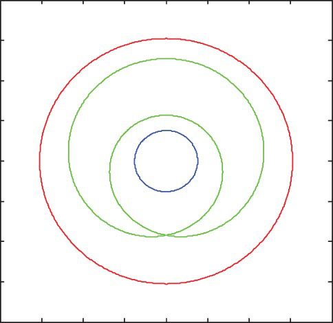
Kinematic Simulation of Grind/Lap of Al2O3 Ceramics with UV-Bonded Wheel
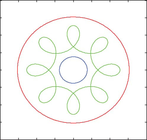
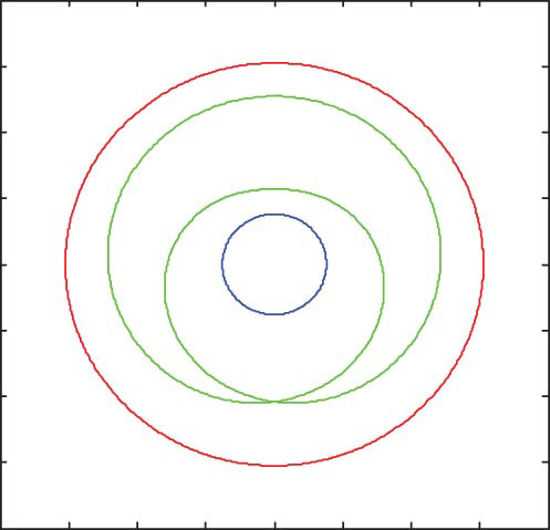
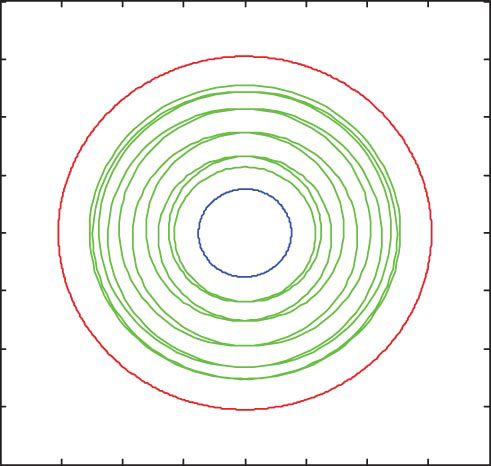
According to the kinematic analysis and dimension measurement of the lapping plate and the workpiece holder, MATLAB was adopted to obtain the traces of workpieces under three different pressures with different revolutions of the lapping plate. Three traces in different colors depict three workpieces in the same holder. Table 8.5 shows the simulated traces of these workpieces under different loads applied with different rotational speeds of lapping plate. Both factors have obvious influences on the path type of the workpiece, which therefore effects the machining results.
Table 8.5
Traces of Workpieces Under Three Different Machining Conditions
| Normal load | Unload | 397 g | 681 g |
| Lapping plate (rpm) | |||
| 10 | 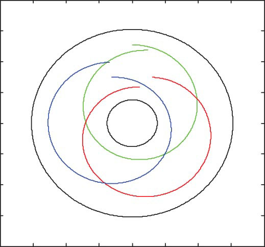 |  | 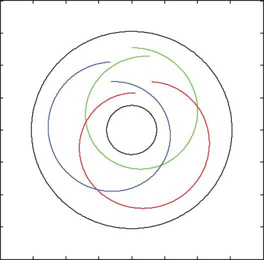 |
| 20 |  | 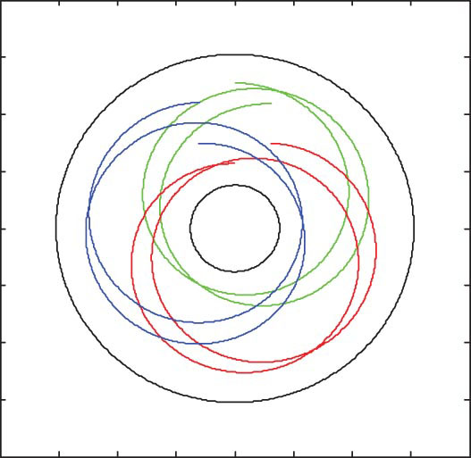 | 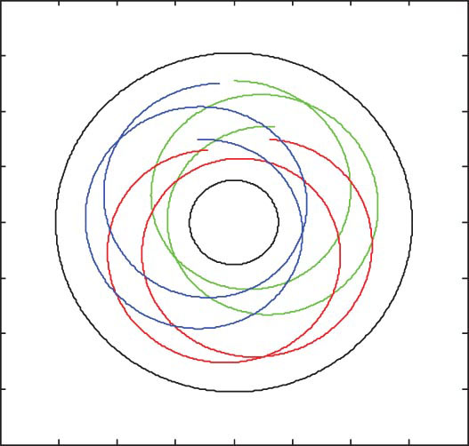 |
| 30 | 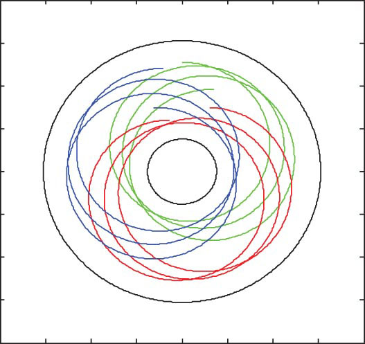 | 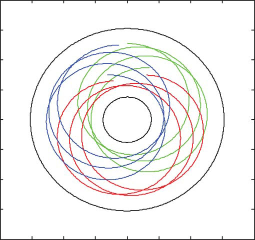 | 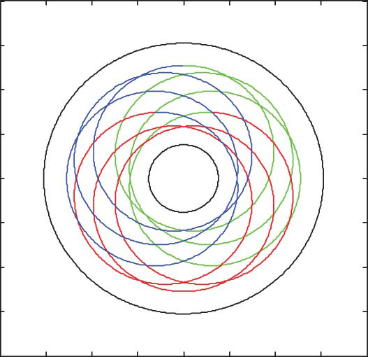 |
| 40 | 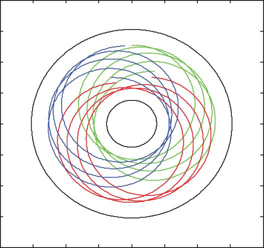 | 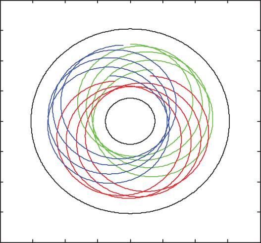 | 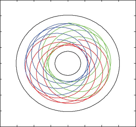 |
| 50 | 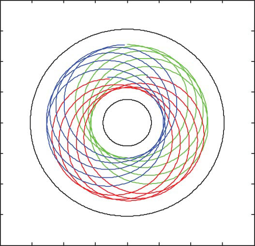 | 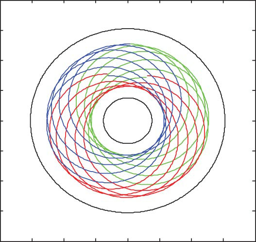 | 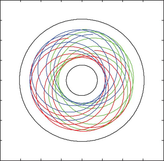 |

As noted in Table 8.5, with different revolutions of lapping plate, some of the traces are evenly distributed on the whole plate while others are not. To study the characters of the UV-bonding abrasive tool in this project, the uniform distribution of the traces are apparently chosen. Therefore, the rotational speed of the lapping plate was set to 40 rpm to achieve a better use of the whole plate.
8.5. Effects of UV-bonded wheel
Effects of UV-Bonding Techniques on Machining Silicon Wafers
For the estimation of lapping performance of the developed UV plate, an experimental program is designed in which the typical rigid brittle-material silicon wafer is selected as the workpiece. Tap water is used as coolant during the lapping. A traditional cast iron lapping plate is also used in the experiments as a reference. During process of traditional lapping, the slurry concentration of the green SiC particles is 20% by weight. The experimental conditions are listed in Table 8.6. In this basic experiment, we used the silicon wafer samples with initial surface roughness of Ra 0.15 μm. Silicon wafers are lapped for 30, 60, 90,120, and 150 min by UV plate and traditional cast iron plate, respectively.
Table 8.6
Experimental Conditions
| Parameter | Value |
| Lapping machine | Lapmaster 12 |
| Work piece | 5″ Al2O3 ceramics |
| Rotate speed (rpm) | 40 |
| Roughness tester | Pocket surf |
| Lapping load (kgf/cm2) | 0.018 |
Silicon wafer is selected first to be machined on the comparison because of the easily machinable properties in manufacturing. Both in conventional lapping and in some new lapping technology, silicon is an important type of material that should be considered. Before going deep, a basic comparison is needed to see the advantage of UV plate lapping technology to conventional lapping process.
The results in Figure 8.22 show that the surface roughness lapped by cast iron plate is not rapidly changed in the first 30 min. The wafer surface machined by an UV plate produces remarkable improvement; the roughness reduced rapidly within the first 60 min and remained stable after that. The cast iron plate is based on conventional loose abrasive lapping method in which the loose abrasive grain was rolled between the workpiece and the lapping plate. The rolling action of each abrasive grain removes the material. For this reason, the conventional loose abrasive lapping process has low machining efficiency, which also leads an improvement in material removal rate of the process. In conclusion, the new UV plate exhibits outstanding machining characteristics.
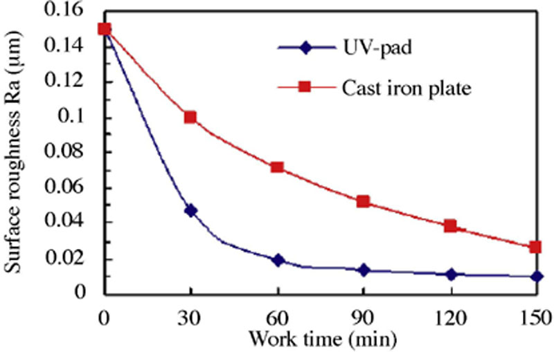
Figure 8.22 Surface roughness of UV lapping and conventional lapping.
Effects of Applied Pressure on Grind/Lap of Al2O3 Ceramics
After proving the effect of UV-bonded diamond wheel by the silicon wafer experiment, another experiment was done for Al2O3 ceramics to study the influence of pressures on the machining results, including surface roughness and weight changes of the workpiece with machining time.
The experiments were done under two pressures, 397 g and 681 g, respectively, with the time interval 15 min at first, and then 30 min. After each interval, the weights and surface roughness of the three workpieces were measured, and the experimental results were as follows:
For the high pressure applied on the workpieces, the weight and surface roughness were shown in Figures 8.23 and 8.24.
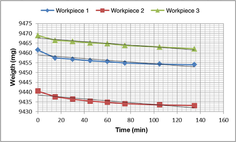
Figure 8.23 Weight changes of workpieces under high pressure.
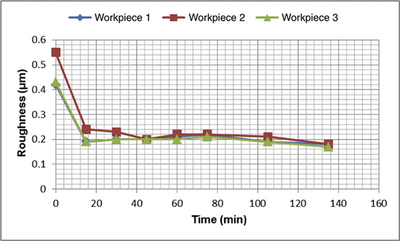
Figure 8.24 Surface roughness of workpieces under high pressure.
Figure 8.23 shows that the linear trend lines of the three workpieces are almost parallel to each other, which means that their variability tendency is almost the same. The abrupt short line in the first 15 min indicates that weights of the workpieces decrease the most, which indicates that the material removal of the workpiece is greater than for any other time interval, and high efficiency was obtained during this time. As the machining time increases to 105 min, the weight changes became progressively smaller. In Figure 8.24, similar to weight changes, roughness variability of the three workpiece resembles each other. And the surface quality was greatly improved in the first 15 min; after that the variability decreased until finally approaching to a constant value.
Compared to the high pressure, Figures 8.25 and 8.26 show the weights and roughness of workpieces under low pressure, which look similar to the results under high pressure conditions. Both the weights and surface roughness decrease sharply in the first 15 min and their variations decrease with time and approach a constant value.
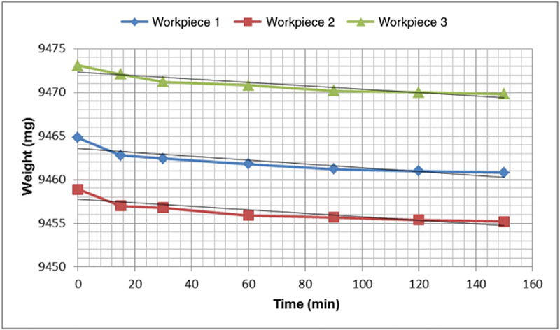
Figure 8.25 Weight changes of workpieces under low pressure.
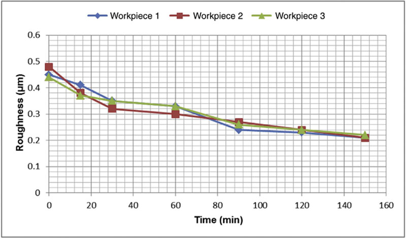
Figure 8.26 Surface roughness of workpieces under low pressure.
In order to see the influence of pressure on the weight and roughness, experimental data of one workpiece under these two pressures were chosen and analyzed. The results can be seen in Figures 8.27 and 8.28.
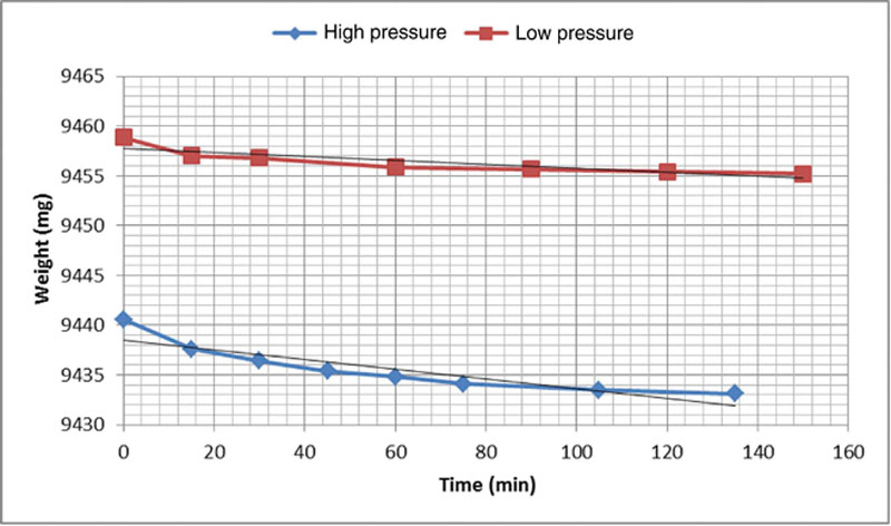
Figure 8.27 Weight variation of workpiece under different pressures.
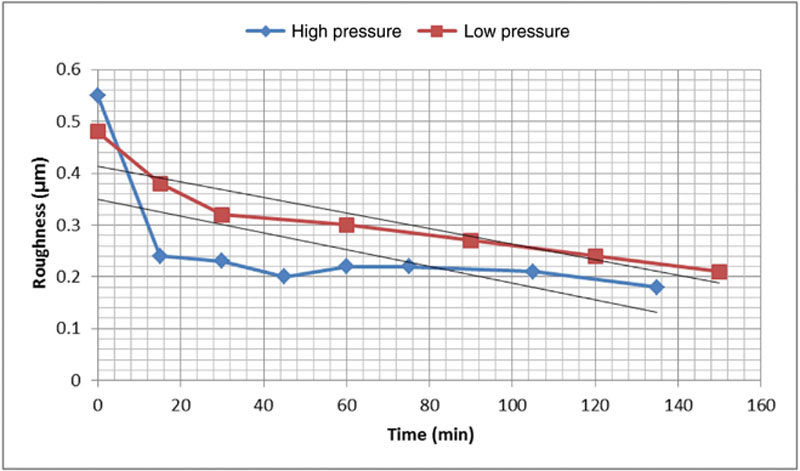
Figure 8.28 Surface roughness variation of workpiece under different pressures.
Both the weight and surface roughness decrease the most in the first 15 min, and then as the time increases, these two values decrease slowly and finally approach constant values. The general variability tendency line under high pressure in each figure is steeper than the low pressure line, which indicates that even if the workpiece has different original parameters (weight and surface roughness), these two values decrease more with higher pressure applied on the workpiece. The influences of pressures on both weight and roughness are apparent in the first 15 min, which are depicted by the steeper lines of these parameters during this time. Difference in surface roughness generated decrease as time passes and finally approaches zero. It can be concluded that the machining efficiency during the first 15 min was much higher compared to other time intervals, much material was removed, and a good surface quality was achieved.
Based on the comparison, it is reasonable to consider that UV-bonded grind/lap is the hybrid of traditional grinding and lapping. Because for UV-bonded grind/lap the diamond particles are softly fixed by the cured-resin bond, the abrasive grains act in the grinding process at the beginning, causing more material removed. After a short time, then, some abrasives separate from the resin act as loose abrasives in the lapping operation and help to obtain a better work surface quality. Therefore, the tendency lines in Figures 8.27 and 8.28 can be better explained using the mechanism of UV-bonded grind/lap. During the first 15 min, the UV-bonded grind/lap plate acts mainly as a grinding wheel. After that, some abrasives separate from the plate and act as free abrasives, which explains why the weight changes slow until finally no obvious change was seen. Similar to the weight changes, the average surface roughness improved the most at first, probably because the original surface roughness of the workpiece is high. After a period of processing, a distinct improvement was shown. Then, the surface roughness of the workpiece also showed greater improvement when compared to the weight, because during the later time intervals, more abrasives fell off the plate and rolled between the workpiece–wheel gap, resulting in a kinematic operation that was more similar to lapping than to grinding.
8.6. Optimal methods for improving grind/lap of ceramics
Influence of Abrasive Powder on Performance of UV-Bonded Diamond Wheel
Abrasives play the most significant role in lapping process, even in UV-resin plate lapping. The abrasives embed into the cure resin and act as a microcutting tool. Therefore, the type of the abrasive eventually affects the lapping performance and surface finish quality. Diamond, as the hardest and most efficient abrasive, is widely used in lapping processes. As we mentioned in the previous chapter, metal-bonded diamond and resin-bond diamond mixture are compared in different experiments, and the MA obviously leads the competition.
For more lapping experiments on plate, we choose MA as the abrasive particle. As a comparative experiment, surface-treated MA (ST-MA) is introduced. The material that coated the surface of the particle determines surface treatment of abrasives; the coating material can be chosen from types of metals, such as cooper, nickel, and titanium. The main purposes of the surface-treatment process are focused in two aspects. First, the coating material can change the weight ratio and increase the brittleness. The machining efficiency is then affected because the fracture of the abrasive is defined by the brittleness of the abrasive particle. On the other hand, the surface treatment changes the shape of the particle by forming more wrinkles on the surface (see Figure 8.29).
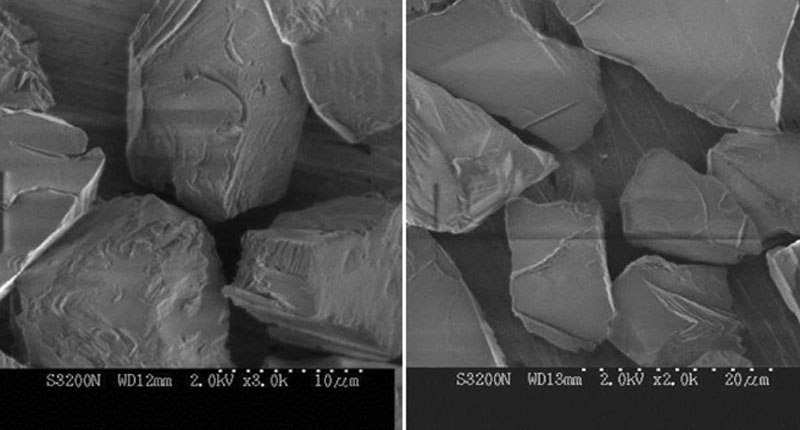
Figure 8.29 Comparison of MA and surface-treated MA.
Lapping Experiment on Aluminum Oxide
In order to see the machining capacity of a UV-resin lapping plate on harder material such as ceramic, aluminum oxide rings will be used as the workpiece in this group of experiments. With an initial roughness of 0.45 μm, the Al2O3 rings are lapped for different periods, with the experiment conditions given in Table 8.7. The roughness test will be done in Pocket Surf.
Table 8.7
Experiment Condition of MA and ST-MA Lapping
| Lapping machine | Lapmaster12 |
| Roughness test machine | Pocket surf |
| Lapping speed (rpm) | 40 |
| Lapping coolant | C270E |
| Lapping time (minute) | 15, 30, 45, 60, 90, 120 |
| Workpiece | ø20 mm aluminum oxide rings |
To get an intuitive understanding, an AFM image of the unfinished ceramic ring surface is given in Figure 8.30.
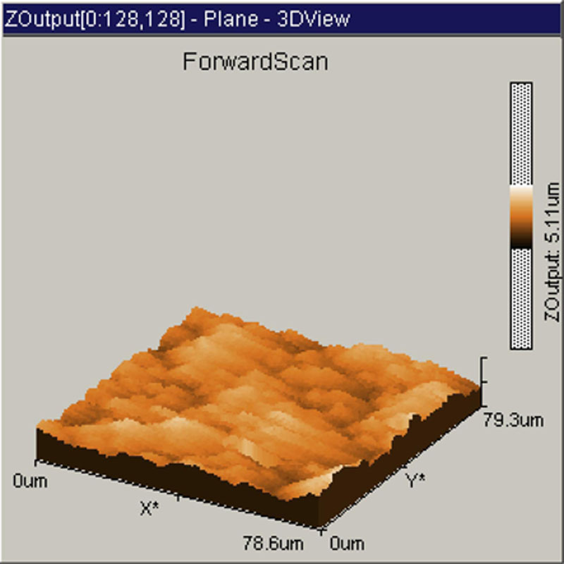
Figure 8.30 Surface AFM image of unfinished ceramic ring.
Experiment Results and Discussion
Figure 8.31 shows the comparison of workpiece surface roughness machined by two kinds of abrasives. The roughness of the surface-treated plate drops from 0.45 to 0.2 and the normal diamond plate is just down to 0.3. The difference of 0.1 is not a small value in this level. For another part, in surface-treated diamond plate experiments, the roughness drops rapidly, especially in the first 15 min. However, for normal diamond experiments, the roughness drops in a smooth curve. When we look at the SEM images of the two diamonds, surface-treated diamond has more ripples and edges, and it is helpful to increase the bonding force between the abrasive and resin. The more wrinkles on the diamond abrasive surface means a larger surface area, therefore the contact area of resin and abrasive increase when compared to the normal MA. In other words, the increased surface roughness and increased surface area of surface-treated MA help to increase the bonding strength in the curing process. The stronger bonding strength of the surface-treated MA plate keeps the abrasives fixed in the plate for a longer time during the lapping process. For this reason, the roughness of the surface-treated diamond abrasive plate drops rapidly with time.
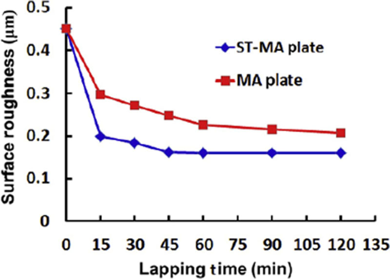
Figure 8.31 Roughness comparisons of MA and ST-MA plate.
Influence of Nanoparticles on UV-Bonded Diamond Wheel Performance
The curing process of the resin is should also be considered in addition to abrasive particles. Nano-scaled materials are now being considered as filler material to produce high-performance composite structures with further enhanced properties. Improvements in mechanical, electrical, and chemical properties have boosted interest in nanocomposite materials in numerous automotive, aerospace, electronics, and biotechnology applications. Nanofibers such as carbon nanofibers, due to their high tensile strength, modulus, and relatively low cost, are drawing significant attention for their potential applications in polymer reinforcement. Various kinds of nanoparticles, such as nano-SiC, nano-ZrO2, nano-ZnO, nano-TiO2, nano-CaCO3, and nanodiamond particles, are widely used as fillers in poly composites to improve mechanical characteristics, especially wear resistance. Based on previous research of nanocomposites, both nanofibers and nanoparticles in particular, significant improvement of wear resistance is expected, mostly by nanoparticles, and is closely concerned with the lifetime of abrasive tools.
In this experiment, the Al2O3 nanoparticle is selected as additives filler in the resin mixture. Purchased from LECO Corporation, these nanoparticles are 50 nm in size, according from the manufacturer. In order to see the improvement of the material properties of resin with nanoparticle, an experiment was carried out with two groups: one group made of diamond abrasive–mixed resins and the other group with diamond abrasive resin mixed with nanoparticles. A 12.5% diamond concentration is selected as a standard in the experiments.
The concentration of the nanoparticles is another parameter of concern. From previous research, we knew that the material properties of the polymer could be changed with a low concentration less than 1% in mass. In this experiment, the nanoparticle concentration was set at 0.75% in mass content as a standard.
The mixture of resin, abrasive diamond, and nanoparticles is stirred for 30 min to make a uniform distribution of the nanoparticles. The stirred mixture was left overnight in order to obtain a better aggregation and to remove internal bubbles. For the cured samples used in the various properties tests, the nanoparticle–mixed resin was placed into different curing molds as illustrated in the preceding figures.
Details of the Nanoparticle-Mixed Resin Material Experiment
The cure depth is a key parameter in photopolymerization, which is complicated and affected by several factors. Previous researchers studied the relationships among photoinitiator concentration, additive suspensions, penetration depth of light, and cure depth. However, resins used in our research are purchase directly from the manufacturer and the chemical compound is already optimized and fixed, so the photoinitiator and chemical compound effect will be ignored. Because of the Al2O3 nanoparticle involved in our resin mixture, the ultraviolet light penetration will likely change with different concentrations. At first, a comparison in cure depth of diamond abrasive mixtures needs to be made to find an optimal curing condition, which then becomes the standard for further experiments. The measurement method used in cure depth is based on ISO 4049. A group of different curing times from 25, 50, 75, and 100 to 125 s was chosen to reveal the trend. Finished samples were cleaned and then measured. Results are shown in Figure 8.32.
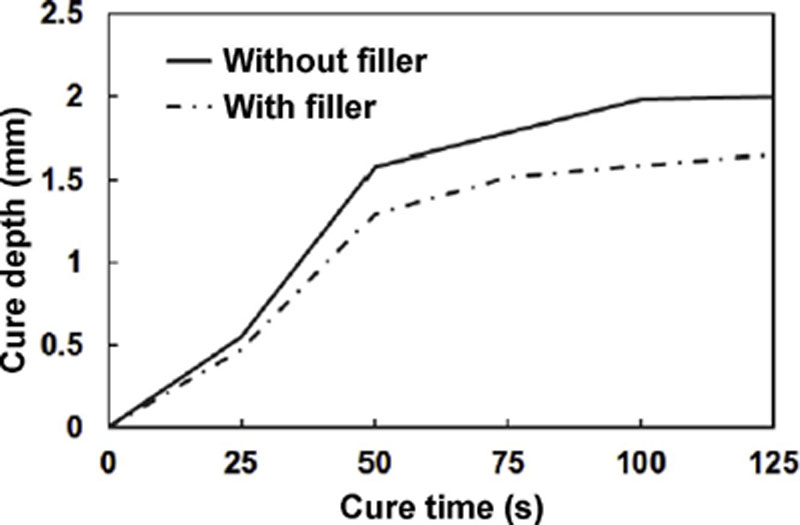
Figure 8.32 Cure depths vs. cure times.
Clearly, the cure depth increased rapidly at the beginning with a drop after 50 s to remain stable at 2 and 1.5 mm. In our experiment, the top layer cured rapidly within the first 50 s because the surface resin absorbed the ultraviolet light energy from the UV bulb immediately, and then the photopolymerization process occurred in which the top layer of resin transformed from liquid to solid state. After the chemical reaction, the cured resin generated a solid film that covered the uncured resin. For light penetration in turbid media such as composite resin, the intensity of light is decreased due to absorption and scattering [14]. In the experiment, the cured resin film, the diamond abrasive powder, the nanoparticle filler, and the resin itself are all factors that affect the light penetration. Therefore, with the cure time increasing in experiment, less and less ultraviolet light penetrated through the resin mixture, permitting less energy to be absorbed by the uncured resin in photopolymerization. The depth difference between mixture with nanoparticle and mixture without nanoparticle is due to the UV energy absorption and refraction by the Al2O3 nanoparticles.
From former researchers’ studies, the thickness of cured resin is not directly proportional to exposure time due the decrease of UV energy penetration in the composites. If 70% of the UV energy is absorbed in the top 0.01″ of coating, then 70% of the remainder or 7% of the initial amount will be absorbed in the second. Thus, a twofold increase in the cure depth requires a tenfold increase in UV intensity [15]. If we just increase the cure time in the curing process, the top layer would absorb too much energy and the surface temperature would be much higher than the thermal limit.
Micromachining is a precision process and the thickness loss of the machining tools, such as lapping plate and polishing pad, could be small – even to a nanoscale – therefore, a millimeter-scale thickness is acceptable in manufacturing of those machining tools. In addition, the curing process can be done on both sides of the workpiece to increase the cure depth if needed.
Nanoscale fillers increase the polymer mixture in both elasticity and strength, and the stress curve comparison shows the improvement (see Figure 8.33). The tensile strain increased almost two times compares to the nonfiller resin, and it means that the material elongation in tensile test increased significantly. When abrasive particles are added into the UV resin, the polymer structure defect takes place due to the size of these microparticles. Therefore, pure resin has better mechanical properties than the abrasives mixture. In our experiment, Al2O3 nanoparticles added as filler into the mixture did not greatly affect polymer structure. Moreover, the nanoparticles have high specific surface energy, while monomer molecules have dipole moments and nanoparticles direct monomers during the polymerization process. A polymer crystal is formed because of the ordered structure, by which the material strength and elasticity improve. On the other hand, the uniformly distributed nanoparticles in polymer act as crystallization centers and increase the resin strength [15].
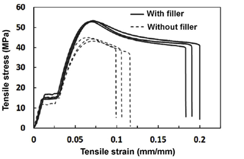
Figure 8.33 Stress curves of nanoparticle–mixed resin.
Figure 8.34 gives an illustration of the resin-bonded lapping process mechanism. Particle 1 and 4 move freely, removing the material by scraping and rolling, which is basically the conventional lapping process that has a lower material removal rate and causes workpiece surface damage. The embedded particle 2 acts as a small cutting tool within the process and obviously, it is comparatively more efficient.
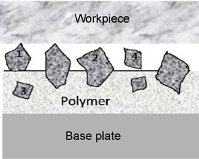
Figure 8.34 Fixed-abrasive lapping processes.
With the material strength improvement, the amount of abrasive particles rolling within the gap between machining tool and workpiece is reduced. The abrasive particle is hard to remove from the polymer, which means they work a longer lifetime as an embedded particle. For this reason, the machining efficiency of the abrasive tools can be improved. Even if the particles drop off from the polymer, the nanoparticle mixture polymer receives less damage due to the stronger bending strength. Meanwhile, some of the free abrasive particles can be embedded in the resin by lapping load because of the soft and elastic material features.
Figures 8.35 and 8.36 show the microscopy of these two mixtures after lapping under the same conditions. Much more surface damage can be seen in the non-nanoparticle mixture because of its weak material properties. When the embedded particles drop off from the polymer, some of the materials around the particle are removed at the same time, and then the rough surface causes more damage on the workpiece.
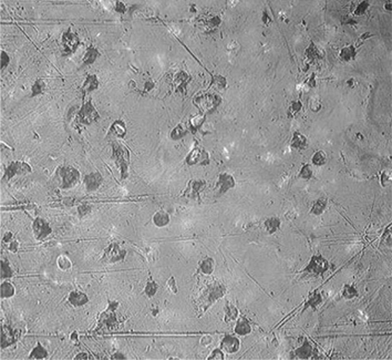
Figure 8.35 Microscopy of the nanoparticle mixture.
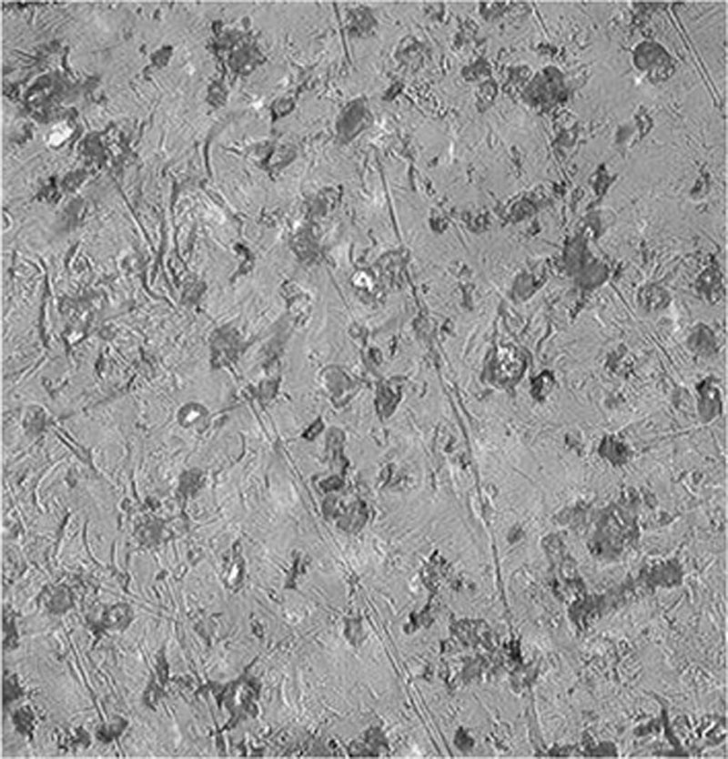
Figure 8.36 Microscopy of the mixture without nanoparticles.
For the nanoparticle mixture, the particle removes little material due to the strong resin polymerization caused by those nanoparticles, and then leaves only a small pit on the surface. These small pits provide room for grain, chips, and fluid during the process and affect the hydrodynamic performance between the workpiece and lapping plate in a good way.
Lapping Performance
The improvement of the nanoparticle–mixed resin shows the benefits in mechanical properties and manufacturing of the plate. The more important aspect is that when we look at the detail of the figures, the roughness of the MA resin plate with nanoparticle remains low after 30 min. On the other hand, the roughness of MA resin plate without nanoparticles decreases gently and remains stable after 60 min or even later. The comparison can be clearly seen in Figure 8.37.
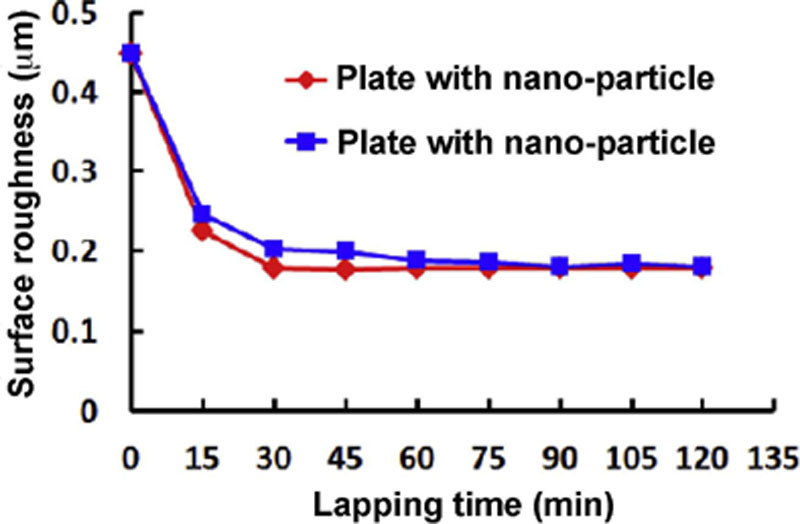
Figure 8.37 Roughness comparisons between plates with and without nano-Al2O3.
..................Content has been hidden....................
You can't read the all page of ebook, please click here login for view all page.