
Chapter 1
Properties of Ceramics
Rainer Telle Institut fur Gesteinshuttenkunde der, RWTH Aachen, Aachen, Germany
Abstract
Although ceramic materials for technical application have been known for more than two hundred years, especially-designed synthetic ceramics, unlike traditional materials in composition, microstructure, and properties, have been developed since approximately 1970. Whereas silicate ceramics and refractory materials are basically derived from natural minerals and manufactured by comparatively simple processing steps, this new class of materials, the “advanced”, “high-tech,” or in Japanese terms “fine” ceramics require an entirely different fabrication route starting from chemically well-defined, fine, highly-purified, and artificial raw materials. These materials have been created for distinct applications in which other conventional materials like metals or polymers have failed. Due to the large variety of chemical, electrical, biological, and mechanical properties that ceramics presently exhibit, there is almost no social and industrial application without ceramics. In the electronic and manufacturing industries, as well as in technologies that require materials sustaining extremely high temperatures and corrosive environments, high-tech ceramics play the role of key materials; novel technologies, processes, and machines are finally made possible only by means of especially tailored ceramics.
Keywords
materials groups
high-performance ceramics
wear mechanisms
abrasion
surface fatigue
adhesion
1.1. Introduction
Although ceramic materials for technical application have been known for more than two hundred years, especially-designed synthetic ceramics, unlike traditional materials in composition, microstructure, and properties, have been developed since approximately 1970. Whereas silicate ceramics and refractory materials are basically derived from natural minerals and manufactured by comparatively simple processing steps, this new class of materials, the “advanced”, “high-tech,” or in Japanese terms “fine” ceramics require an entirely different fabrication route starting from chemically well-defined, fine, highly-purified, and artificial raw materials. These materials have been created for distinct applications in which other conventional materials like metals or polymers have failed. Due to the large variety of chemical, electrical, biological, and mechanical properties that ceramics presently exhibit, there is almost no social and industrial application without ceramics (Table 1.1). In the electronic and manufacturing industries, as well as in technologies that require materials sustaining extremely high temperatures and corrosive environments, high-tech ceramics play the role of key materials; novel technologies, processes, and machines are finally made possible only by means of especially tailored ceramics.
Table 1.1
Classes of Ceramics and Fields of Application
| Materials Group | Properly | Application |
| Compressive Strength | Bricks | |
| Traditional | Density + Strength | Ceramic Hollow Ware |
| Ceramics | Density + Wear Resistance | Structural Clay Products |
| Heat and Corrosion Resistance | Refractories | |
| Structural | Hardness | Grinding Grits and Disks |
| Ceramics | Strength + Toughness | Engineering Ceramics |
| Biocompatibility, Bioactivity | Bioceramics | |
| Nuclear Properties | Nuclear Ceramics | |
| Corrosion Resistance | Chemoceramics | |
| Catalytic Properties | ||
| Functional | Electric Resistivity | Electroceramics |
| Ceramics | Dielectric Properties | |
| Magnetic Susceptibility | Magnetoceramics | |
| Diaphaneity, Anisotropic | Optoceramics | |
| Optical Properties |
Surprisingly, this development was initiated by metal scientists or -more precisely - by powder metallurgists rather than by traditional ceramists. The reason for this is that the manufacturing route used for the production of metallic parts by powder molding and compaction followed by subsequent consolidation by a heat treatment, i.e. sintering, was investigated fundamentally since the turn of the century for steel, refractory metals, and since 1920, for hard metals which could not be casted or molded otherwise. With regard to natural multicomponent raw materials and comparatively simple chemical systems, the basic understanding of these originally “ceramic” processing procedures was much easier than in the case of traditional ceramics. Thus, the break through in the science of sintering was achieved in 1970 to 1980 yielding knowledge on the reproducible production of high-performance powder and metallurgically-prepared parts. Being easily transferred to ceramics of “simple” composition, the foundation for the development of tailored microstructures with as-desired properties was created. The simultaneous development of high-toughness zirconia and highly wear-resistant silicon nitride ceramics indicated a promising way to overcome the most important disadvantage of traditional ceramics: their brittleness. The capability of the entire control of residual porosity together with the so-called transformation toughening by zirconia as well as the science of phase relationships in multicomponent systems that yielded the opportunity to synthesize silicon nitride -based high-temperature materials initiated a world wide boom in ceramic research and development. Figure 1.1 shows one of the many predictions for future markets and turn-over opportunities related to the various branches of application. To further the collaboration between industry and research institutes, large investments in ceramic development and research programs by industrial countries have been implemented. As a consquence of these efforts, a novel understand of matter was achieved in the field of fracture mechanics yielding insights in toughening phenomena and reinorcing strategies for static and dynamic load. Models for the prediction of the long-term behavior of complex parts have been derived, and the term “fatigue” was described in respect to brittle fracture originating from microstructural defects which have been quantified by means of statistics. High-resolution electron transmission microscopy gave information about the internal structure of grain boundaries and thus enhanced the development of creep resistant high-temperature silicon nitride based monoliths. Micro- and nanoscaled molding techniques brought about new possibilities to manufacture electrically and electronically active ceramics: ubiquitous components of modern electronic devices. Additionally, the invention of the ceramic high-temperature superconductors contributed to the tremendous increase in materials research.
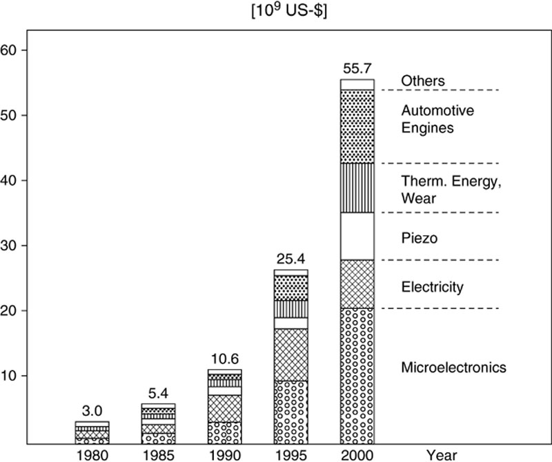
Figure 1.1 Market forecast for high-performance ceramics. (Courtesy, Hoechst 1988)
Not in all cases, however, have ceramics been able to meet the sometimes extraordinarily high demands of the applying industry. The progress in understanding the particular influence of the manufacturing procedures to the microstructure and mechanical properties was slower than expected. The market did not develop as projected due to the lack of reliability of the ceramic parts and due to problems in its acceptance by construction engineers. Furthermore, the request for high quality products led to high-cost raw materials and products which had some time to compete with metals or even with polymers. Thus, some strategic investments by big companies came too early and turned out risky, especially in Europe, but the competition with Japan and the United States, as the two most important providers of advanced ceramics, was severe. Imports from Japan where part development and production was strongly supported and funded by the government, were sometimes preferred to imports from the European providers.
Today (1994-96), the worldwide economic problems govern the entire market. The exponential increase in market demand for high-tech ceramics is stopped, even in Japan (Figure 1.2). New machining techniques for shaping sintered parts to final dimensions, however, have significantly lowered the costs of structural parts. On the other hand, more accurate analyses of the mechanical properties being really requested for ceramics in automotive engines show a clearly lower level of performance being necessary than aimed at before, hence the dramatically decreasing costs in raw materials, processing, and final machining. Together with new fields of application (e.g. tools for semiconductor fabrication, Figure 1.2) these facts bring about new prospects for high-tech ceramics in the near future, because they are still what they have been designed for: key materials of a modern technology.
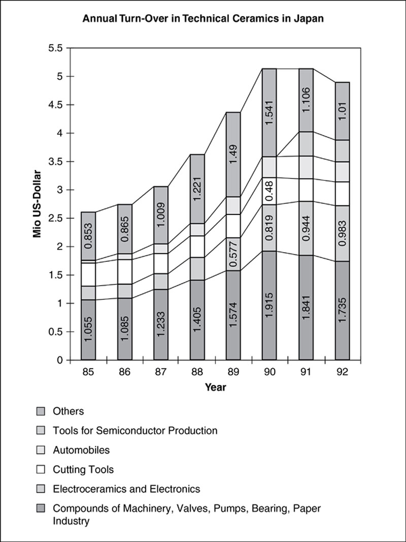
Figure 1.2 Fine ceramic market development in japan as it is. (Courtesy, Hitachi Metals Inc., 1996)
One field of application that developed with an increasing intensity, as was predicted, is related to the excellent wear behavior of ceramics: the application as cutting tools and grinding grits. In the last decades, ceramic grinding and cutting tools initiated a strong impact to the manufacturing technology of metals. New turning and milling machines were developed; these required high hardness and toughness materials that were capable to work at very high feed rates, speed, and therefore at high temperatures yielding smooth surfaces free of damage. Numerically controlled manufacturing techniques, the strong increase in process reliability, and quality reproducibility were made possible by especially developed alumina and silicon nitride ceramics. The most important step towards high performance ceramics was the basic understanding of fracture initiating mechanisms and strategies to minimize the material-inherent brittleness.
Functional ceramics in the sense of components of electronic or electric devices such as capacitors, piezo ceramics, chip carriers, insulating housings, spark plugs, etc., are prepared by thin film techniques or extrusion processes, sometimes followed by glazing, yielding suitable surface roughness and sufficient accuracy in final dimensions. Grinding and polishing operations are usually not requested as an additional finishing step. Therefore, this class of ceramics will not be treated further in the following paragraphs. Structural ceramics, however, which have to sustain external loads and to fit into a mechanically active construction consisting of a large variety of different materials, e.g. an engine, must strictly meet the desired final dimensions and surface qualities to guarantee the requested properties in service with sufficient reliability and life time.
Since hardness, stiffness (Young’s modulus), toughness, and strength are the most important mechanical properties of structural ceramics determining the wear resistance, the goal of this article is to introduce one to the fundamentals of material-inherent properties as well as of wear mechanisms and reinforcing strategies which have been applied to technical ceramics. This is of a particular importance because grinding and polishing (i.e., mechanical material removal during shaping) of ceramics which have been especially optimized to resist material removal (i.e., wear in service) is accordingly difficult. These conflicting properties, ease in machining and simultaneous resistance in service, are surprisingly not yet regarded by the material developers nor by the manufacturing engineers.
Additionally, a basic understanding will be developed to enable the reader to choose suitable material combinations for appropriate applications and to understand the difficulties in manufacturing but also the risks and origins of failure during service live. Besides parts of structural ceramics, grinding grits or small cutting tools suffer basically from the same problems and can therefore be strengthened by the same methods. Another goal of this article is, however, to show the chances and the limits of a future materials development.
1.2. Wear mechanisms of ceramics materials
Because of their partially covalent and partially ionic chemical bonding, ceramics are extremely hard and corrosion resistant and therefore excellent wear resistant materials at both room temperature and high temperatures. One important limiting factor is, however, their inherent brittleness. High stiffness, high hardness, and consequently the brittleness, are based upon the little deformability of the crystal lattice in contrast to metals and polymers. At low temperatures, strain energy in the vicinity of a crack tip cannot be released by dislocation movement or creep. In comparison to metals, the activation energy for the movement of dislocations is so high that the ultimate fracture strength is by far exceeded. As the crystal structures of ceramic possesses lower symmetries compared to metals, even an increase of temperature closest to a melting point does not result in the activation of more than two or three dislocation slip systems. Therefore, the plastic deformability remains poor which means that the brittleness and also the high hardness persists to high temperatures. Talking in terms of stress-strain relationships, the linear elastic range of the stress-strain curve is terminated by immediate catastrophic fracture releasing the entire stored elastic strain energy (Figure 1.3). This is in particular the case if the stored elastic strain energy exceeds the work of fracture required for the formation of a new crack surface or if at a tip of a preexisting crack or microstructure inhomogeneity tensile stresses are accumulated in the order of the theoretical strength of the material.
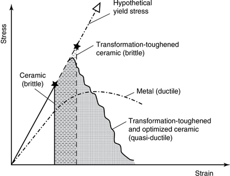
Figure 1.3 Stress-strain curve for ceramics and metals
One measure of work of fracture is related to the critical stress intensity factor KIc also denoted to as fracture toughness. The critical stress intensity factor describes a particular stress intensity at a tip of a crack which is required to make a crack propagate. The ultimate fractures strength σc is thus a very important mechanical parameter which describes the critical tensile or bending stress which is required to initiate the crack. For brittle materials like glasses and most of the non-reinforced ceramics, fracture strength and fracture toughness are linked by the so-called Griffith-equation:
 (1.1)
(1.1)This equation Y means a geometry factor which describes the shape and the position of a microstructural inhomogeneity, e.g., a crack or a pore, and a the maximum elongation of this particular inhomogeneity, e.g., the crack length or the pore diameter. As it will be shown later, this fracture mechanical equation does not only correlate the basic mechanical parameters but also shows the direction of a further improvement of properties and thus inherently contains the basic understanding of fracture statistics. Due to the fact that geometrical parameters are involved in the description of fracture initiation, the materials strength cannot be described as a single constant being valid for a certain product but is, instead, a function of the probability of the spatial and size distribution of supercritical microstructural defects.
Since the Young’s modulus is given by the stress-strain relationship, another mechanical property is still missing which is very important for cutting tools and grinding materials: the hardness. The hardness is defined as the resistance of a material against the penetration by a testing device. From the viewpoint of physics, the hardness is related to the lattice properties of crystals and can be therefore derived solely from interatomic forces. In practice however, the hardness is a combined property which involves microstructural characteristics such as porosity, grain size, grain boundaries, dislocation movement, cleavage fracture, and other geometry- and temperature dependent bulk properties.
In the case of cutting tools and grinding grits, these mechanical properties cannot be discussed at room temperature alone. Due to the very small surface area being in contact with the material machined, very high temperatures may develop at the interface between the work material and the cutting material. Accordingly, the temperature dependence of strength, fracture toughness, hardness, and Young’s modulus have to be discussed as well as other thermo-physical properties such as thermal expansion and thermal shock behavior. Additionally, at the contact between ceramics and metals, chemical reaction may be initiated under the high contact pressure and the high temperatures.
Although many theories in fracture mechanics have been developed to describe the service behavior of brittle materials, the prediction of the wear properties from the static mechanical properties is not easy since the interaction between wear couples is manifold. Usually, tool and work material is not simply in contact with each other but a third medium such as cooling agents, lubricants, abrasive additives, chips of the work piece, hard material, and certain atmospheres may form an environment which contributes strongly to the particular wear mechanisms. Taking this third medium into account, one can distinguished four basic wearing effects:
• surface fatigue,
• abrasion,
• adhesion, and
• tribochemical reactions.
Figure 1.4 summarizes schematically the basic interactions, mechanisms, and effects that can be observed in wear couples. Material removal by formation of adhesive bridges between tool and work material, crack formation by delamination, and opening of grain boundaries are visualized for the case of sliding wear in Figure 1.5. From both figures, it becomes evident that chemical interactions contribute to the wear behavior in addition to the mechanical interaction. In the following paragraphs, the particular wear mechanisms are described in detail.
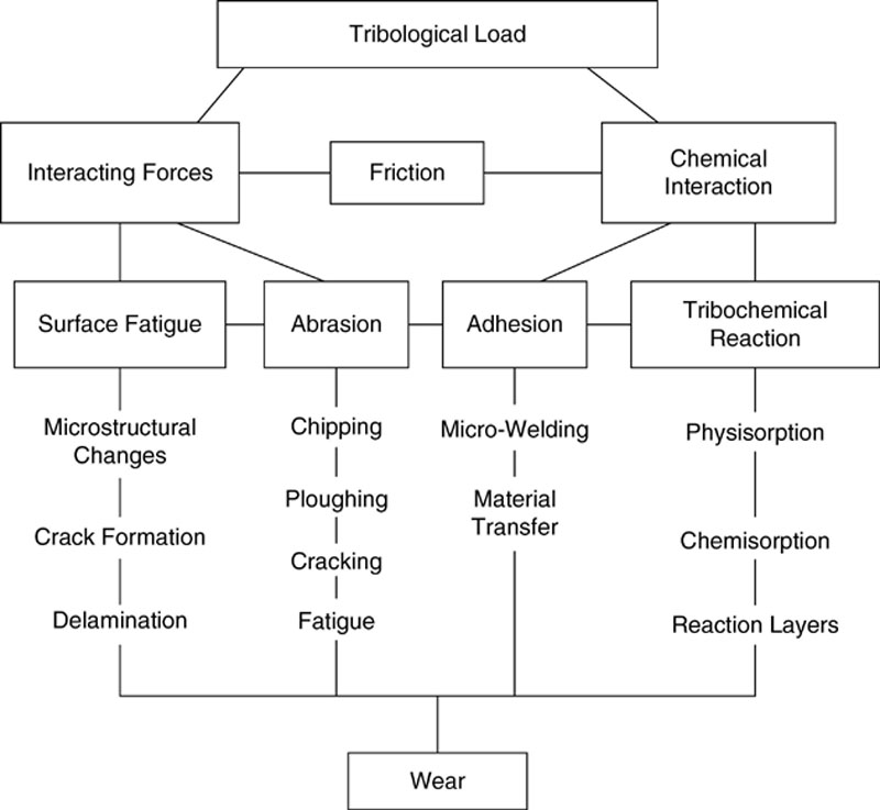
Figure 1.4 Principal mechanisms and effects of wear
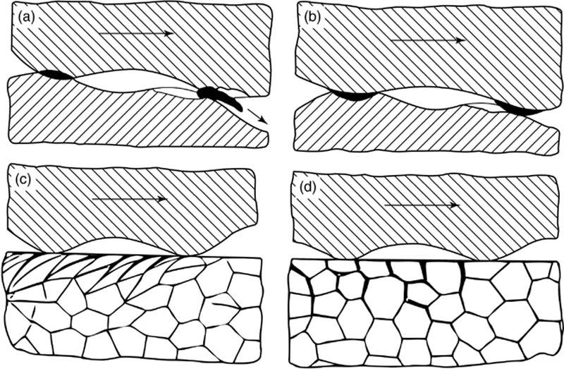
Figure 1.5 Surface effects of sliding wear (after Zum Gahr)
(a-b) Material; removal by adhesive bridges and their chip-off
(c) Crack formation by delamination (grain boundary sliding and cleaving)
(d) Crack formation by grain boundary opening
Abrasion
The term “abrasion” comprises all groove-forming mechanisms on the surface of a material by micro chipping and micro ploughing. This mechanism is a consequence of a high ratio of the hardness of the tool material and the work material. An estimation of this hardness ratio must, however, consider the dramatic decrease with temperature in ceramic materials while metals may reveal an increasing hardness by work hardening effects. Additionally, the dynamic hardness of a metal may be considered higher than the hardness measured by indentation techniques due to incorporated carbide particles. Generally, the ratio of tool material hardness to work material hardness should not be less than 1.5 to 1.7.
Although grooving is an evidence for plastic deformation, the pull-out of chips and particles from the microstructure of both cutting tool and work material must also be considered. Accordingly, the local fracture toughness must be taken into account. Model wear tests performed on a large variety of material couplings indicate that a correlation of the wear amount, or wear rate, to both hardness and fracture toughness is generally possible. Several empirical formulae have been developed from pin-on-disc tests relating the wear resistance to fracture toughness times hardness of several exponents. Table 1.2 shows some more important empirical formulae that have been proved to fit well with experimental results. The Evans-Wilshaw-Equation is accepted most for ceramic-ceramic pairs. It is evident from this expression that the high hardness must always be combined with a high fracture toughness to yield suitable wear properties. Surprisingly, the infl-uence of fracture toughness is more important than the hardness as can be concluded from the particular exponents.
Table 1.2
Empirical Relations Between Wear Resistance Factor R and Mechanical Properties
| R = W-1∼K2ICH3/2 | Hombogen |
| R = W-1∼K3/4ICH1/2 | Evans & Wilshaw |
| R = W-1∼K2ICH-1/2 | Zum Gahr |
| R = W-1∼K4/3H-1/9 | Ruff & Wiederhorn |
R = inverse volume loss W.
Surface Fatigue
The term “surface fatigue” covers the combination of wear mechanisms, operating within a surface layer of several micrometers in thickness, that are caused by tangential shear stresses at the material surface as well as by iterative impacts. The surface fatigue is characterized by crack formation along the grain boundaries or cleavage planes starting at the surface and progressing continuously to greater depth by subcritical crack growth. This wear mechanism is especially detrimental since the ultimate depth of the cracks cannot be estimated by looking at the surface of the material. Upon service, however, they can grow slowly to more than 100 μm extension becoming the rupture-initiating failure of the part by reaching the critical length as given by the Griffith Equation. Tool failure by surface fatigue is a characteristic for cycling compressive and tensile loading as observed by, e.g., intermittent cutting operations or by reverse sliding of seals. A similar effect may cause the pull-out of ceramic grinding grains if the particle interface to the binder is slowly and steadily subjected to cycling loads and debonds.
Subcritical crack growth by repeated impact may be supported by iterative thermal shock. In case of the grinding operation, for instance, the temperature during the milliseconds of cutting action may give rise to a strong temperature increase at both the cutting tip and the work material surface area in contact. Local stresses may develop due to the accordingly introduced thermal gradients, due to an isotropy effects, or due to differences in thermal expansion of the various compounds. Since crack growth is the basic mechanism of this wear effect, a high fracture toughness, a high thermal conductivity, and the low thermal expansion coefficient of the ceramic material is requested.
Adhesion
Adhesion comprises the chemical interaction between the wear materials. Depending on the affinity between cutting tool and work material, a local joining or even welding of both materials may occur. The binding forces may become so high that chips may be pulled out or chipped off from the work material, e.g., the metal debris of the work material may adhere at the ceramic cutting tool. This effect is also known as material transfer and is responsible for the fact that the cutting tool is not in contact any more with the work material. Figure 1.6 shows several models to explain the effect of adhesion. Besides clamping as a mechanical effect, diffusion of atoms and ions, electron transfer, or dielectric polarization effects are considered to be responsible for the development of chemical bonding.
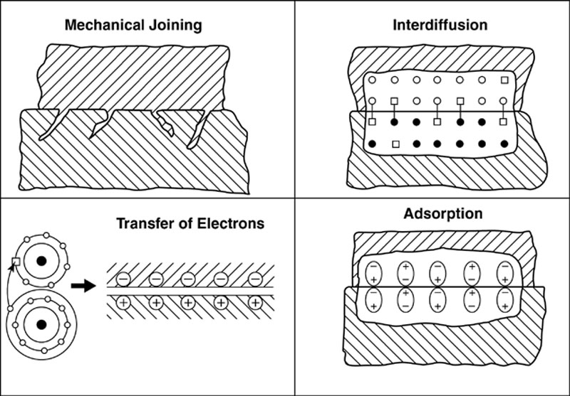
Figure 1.6 Possible reasons for adhesion (after Zum Gahr)
Tribo-chemical Reactions
Tribo-chemical reactions between wear couples, e.g., tool material and work material may occur if both materials are not in a thermodynamic equilibrium, especially at higher temperatures. In the contact area, a new reaction product is formed which is usually removed together with the chip or adheres at the cutting tool material. These reactions may also be caused by environmental materials like lubricants or atmospheric gases. The chemical wear becomes visible by very smooth and lustering surfaces or by deformation of built-up cutting edges. To avoid tribo-chemical reactions, appropriate tool material selections may be recommended as well as lower cutting powers to avoid the generating of high temperatures.
Combined Wear Mechanisms
Of course, the above-mentioned mechanisms do not occur separately but in combination with each other where they are not acting additively but multiplicatively. Environmental material like lubricants, gases, or tribo-chemical reaction products may infiltrate surface cracks opened by dynamic fatigue, possibly initiating new stress corrosion mechanisms and therefore enhancing the subcritical crack growth. Similarly, abrasion may be drastically accelerated if the surface of the material is partially dissolved by chemical attack or if the grain boundaries are weakened. Furthermore, surface fatigue may contribute to enhanced abrasion by weakening the grain boundary strength by a cycling load that facilitates the pull-out of single particles.
The combination of adhesion and tribo-chemical reaction causes even more severe wear problems. Figure 1.7 shows an example where both materials have adhesive contact at the apices of the surface roughness while including reactive environmental material in the adjacent concave surface areas. Chemical reactions may now result in the formation of a passivation layer on both surfaces preventing a further chemical attack. Together with the material removal by adhesive contact, however, this passivation layer may be destroyed whenever it is newly formed. Consequently, the concave structures are filled with debris acting as very small abrasive particles enlarging the concave structures by interactive microgrinding effects. This synergetic wear mechanisms result in a very fast pull-out of the protruding hard material grains.
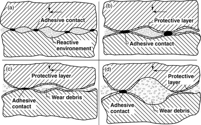
Figure 1.7 Synergetic effects of combined adhesion and tribo-chemical reaction (after Zum Gahr)
(a) Adhesion
(b) Formation of passivation layer
(c) Formation of debris by adhesive pull-out
(d) Removal of passivation layer by wear debris
1.3. Fundamental properties and selection criteria
For ruling out wear resistant materials for special applications, the specific mechanical properties such as hardness, toughness, strength, thermal conductivity, oxidation resistance, and chemical inertness against the work material must be considered as functions of temperature in service. For this, hardness, thermal conductivity, oxidation resistance, and chemical inertness are considered intrinsic properties that can be assigned to a particular chemical compound; they follow the known rules of mixtures if another compound is added to form a composite material. Fracture toughness, fracture strength, and consequently also thermal shock resistance are basically influenced by the microstructure and can therefore be modified by certain optimization techniques. This chapter is devoted to the intrinsic properties whereas the improvement strategies will be addressed in the chapter: Reinforcing mechanisms.
Hardness
It has been shown already that, besides fracture toughness, hardness is the property determining the resistance against abrasive wear. Figure 1.8 shows the temperature dependence of hardness for some important ceramic materials in relation to diamond and cubic boron nitride (CBN). Due to its perfect covalent bonding, diamond is the hardest natural and synthetic material known. Theoretically, other compounds have been predicted by calculation of interatomic forces having a hardness superior to that of diamond. Compounds like C3N4 are, however, not stable under technically available pressures and are therefore only hypothetical candidates for hard materials but nevertheless investigated as coatings on silicon nitride substrates. Although diamond is a high-cost product, cutting tools made of polycrystalline diamond or grinding grits consisting of diamond particles are widely used for grinding, milling, and machining treatments of ceramics as well as metals. Because of its metastability under normal pressure, diamond has the disadvantage of transforming to the stable graphite phase at temperatures above 500-600 °C. Upon transformation from the cubic to the hexagonal modification with a weakly bonded layered structure, diamond undergoes a lattice softening which causes a dramatic decrease of hardness. A similar behavior is observed of cubic boron nitride which is also a high-pressure compound with the same structure like diamond. It also turns to hexagonal boron nitride (hBN) graphite structure and shows, therefore, the same decrease in hardness but at much lower temperatures. The material ranking at the third order is boron carbide, B4C, which does not undergo phase transformation. It is followed by silicon carbide, SiC, silicon nitride, Si3N4, and finally by a series of transition metal borides and carbides which have, however, only 20 to 25% of the hardness of diamond and 50% of the hardness of boron carbide. The first oxide ceramic of interest is boron suboxide (B6O) which is technically unimportant up to now followed by alumina (A12O3), and spinels (MgAl2O4) ranging at 2000 kg/mm2 and less (Figure 1.8). In comparison to these materials, zirconia (ZrO2) is rather soft with the hardness of 800 to 1100 kg/mm2 at room temperature and the strength further decreases upon heating. Zirconia, however, is a very important compound in oxide ceramic composites being responsible for a strong increase in fracture toughness as will be shown later. Another grinding and polishing material, silica (SiO2) starts with a hardness on the order of 600 kg/mm2 but shows a transient sudden increase in hardness at 573 °C to 1500 kg/mm2 due to the reversible transformation to a high temperature structure.
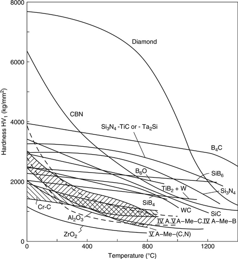
Figure 1.8 Temperature dependence of hardness of ceramics
Fracture Toughness
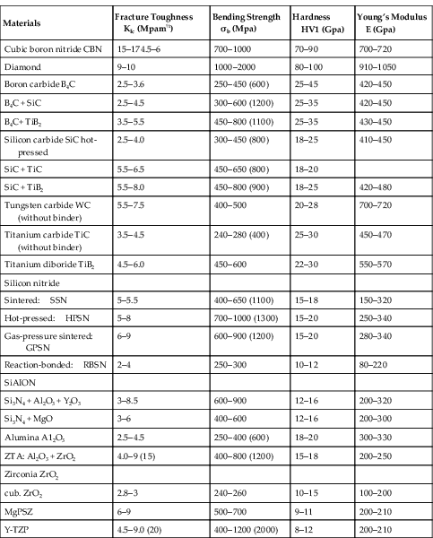
The inherent fracture toughness of single phases in terms of therefore isolated particles depends strongly on the crystal lattice and the interatomic forces determining the bonding of the particular cleavage planes. Particular lattice planes being densely occupied by an electrostatically equivalent amount of anions and cations (typical for rock salt) or weakly bonded planes separating low-energy substructural units with internally saturated bonds (typical for clays and micas) may be preferential paths for cleavage. Alumina, for instance, shows a preferential cleavage along the rhombohedral planes, whereas the other planes exhibit an irregular conchoidal rupture surface like glass. This can be observed sometimes upon grinding of alumina ceramics if single particles are partially pulled out. Boron carbide, silicon carbide, zirconia and silicon nitride particles usually show a conchoidal fracture surface where, e.g., high-temperature superconductors exhibit a pronounced cleavage along the basal plane. In grinding tools, single diamond grains fail sometimes by perfect cleavage along the pyramidal (111) plane whereas CBN fractures preferentially along the rhombohedral (101) plane. In the case of polycrystalline ceramics, however, the fracture toughness is strongly affected by the micro-structure, i.e., by grain size, grain shape, intergranular phases, and residual stresses influencing the crack propagation. Additionally, the measures of fracture toughness are extremely dependent on the testing procedure. In Table 1.3, some data of the critical stress intensity factor K.C. are listed for single phase materials. Extraordinarily high values are reported for CBN, diamond, tungsten carbide, and titanium carbide. In case of the superhard materials, this data have been calculated or measured by indirect methods since appropriate test samples of diamond or cubic boron nitride are not available. In comparison to hard metals (Co-bonded WC), the fracture toughness of the pure hard materials such as SiC, Si3N4, and A12O3 are rather poor. As mentioned before, an increase of fracture toughness can be obtained by a tailored microstructural design in multicomponent ceramics where a doubling of the values is not unusual. This is, for example, evident in case of alumina ceramics which are reinforced with zirconia or in the case of SiC-TiB2 composites (Table 1.3).
Table 1.3
Mechanical Properties of Ceramics
| Materials | Fracture Toughness KIc (Mpam½) | Bending Strength σb (Mpa) | Hardness HV1 (Gpa) | Young’s Modulus E (Gpa) |
| Cubic boron nitride CBN | 15–174.5–6 | 700–1000 | 70–90 | 700–720 |
| Diamond | 9–10 | 1000–2000 | 80–100 | 910–1050 |
| Boron carbide B4C | 2.5–3.6 | 250–450 (600) | 25–45 | 420–450 |
| B4C + SiC | 2.5–4.5 | 300–600 (1200) | 25–35 | 420–450 |
| B4C+ TiB2 | 3.5–5.5 | 450–800 (1100) | 25–35 | 430–450 |
| Silicon carbide SiC hot-pressed | 2.5–4.0 | 300–450 (800) | 18–25 | 410–450 |
| SiC + TiC | 5.5–6.5 | 450–650 (800) | 18–20 | |
| SiC + TiB2 | 5.5–8.0 | 450–800 (900) | 18–25 | 420–480 |
| Tungsten carbide WC (without binder) | 5.5–7.5 | 400–500 | 20–28 | 700–720 |
| Titanium carbide TiC (without binder) | 3.5–4.5 | 240–280 (400) | 25–30 | 450–470 |
| Titanium diboride TiB2 | 4.5–6.0 | 450–600 | 22–30 | 550–570 |
| Silicon nitride | ||||
| Sintered: SSN | 5–5.5 | 400–650 (1100) | 15–18 | 150–320 |
| Hot-pressed: HPSN | 5–8 | 700–1000 (1300) | 15–20 | 250–340 |
| Gas-pressure sintered: GPSN | 6–9 | 600–900 (1200) | 15–20 | 280–340 |
| Reaction-bonded: RBSN | 2–4 | 250–300 | 10–12 | 80–220 |
| SiAION | ||||
| Si3N4 + Al2O3 + Y2O3 | 3–8.5 | 600–900 | 12–16 | 200–320 |
| Si3N4 + MgO | 3–6 | 400–600 | 12–16 | 200–300 |
| Alumina A12O3 | 2.5–4.5 | 250–400 (600) | 18–20 | 300–330 |
| ZTA: Al2O3 + ZrO2 | 4.0–9 (15) | 400–800 (1200) | 15–18 | 200–250 |
| Zirconia ZrO2 | ||||
| cub. ZrO2 | 2.8–3 | 240–260 | 10–15 | 100–200 |
| MgPSZ | 6–9 | 500–700 | 9–11 | 200–210 |
| Y-TZP | 4.5–9.0 (20) | 400–1200 (2000) | 8–12 | 200–210 |
Fracture Strength
The temperature dependence of the fracture strength is documented for some hard materials in Figure 1.9. The values reported here are only valid for some particular microstructures. In general, room-temperature strength and high-temperature strength depend very strongly on the size distribution of microstructural inhomogeneities and intergranual phases. In the case of silicon nitride ceramics, for instance, materials have been developed with a room-temperature strength exceeding 1000 MPa and maintaining this value up to 800 to 1000 °C followed by a drop to 600-800 MPa at higher temperatures. Other silicon nitride materials may start with the lesser strength of 800 MPa but may maintain this value up to more than 1200 °C. This depends not only on grain size and related flaws but also on the volume, fraction and glass transformation temperature of the intergranual phases. As shown in Figure 1.9, the strength of ceramics remains usually constant up to temperatures of 600 to 800 °C followed by a more-or-less decrease. It should be mentioned that in case of nonoxide ceramics, the values reported in Figures 1.8 and 1.9 are only valid for non-oxidizing atmospheres.

Figure 1.9 Temperature dependence of fracture strength
Certainly, oxidation of the ceramics along the grain boundaries is followed by a strong stress corrosion-induced crack propagation during service and therefore by a significant decrease in residual strength at temperatures above 600 °C. Besides silicon nitride and sialons, silicon carbide behaves best since it exhibits the best oxidation resistance maintaining its strength to temperatures exceeding 1000 °C due to the lack of glassy intergranual layers and by building up a passivation layer of silica which may even close surface cracks. The disadvantage of the glassy phase-containing materials is furthermore the plastic deformation by creep which is a significant risk of failure in silicon nitride-based tool materials.
Thermal Conductivity
The thermal conductivity plays a significant role especially in case of the selection of cutting tools, wear parts being in sliding contact, or structural parts being subjected to thermal cycling. In contrast to metals with an excellent temperature conduction, the contact temperature of, e.g., ceramic cutting tools may increase to more than 1200 °C at the cutting edge and may therefore create stresses combined with a risk of thermally-induced fracture. In case of diamonds as grinding grits, the diamond acts as an thermal sink due to its extraordinarily high thermal conductivity.
In the case of ceramic tools, intermittent cutting, repeated impact, and grooving action of single particles results in the most critical thermal loading followed by thermal shock and thermal fatigue failure. In case of ceramic work materials, storing of heat in small surface volumes may create a local temperature increase close to or even above the melting point; this, in cooperation with the multiaxial stresses makes the observed plastic deformation understandable. Therefore, the thermal conductivity is a very important factor for the applicability of a wear resistant. From Figure 1.10, it is obvious that diamond is the material with the highest thermal conductivity due to its perfect covalent bonding. It is followed by high purity aluminum nitride (A1N) which is developed for electronic substrates and heat sinks but is unsuitable as a hard material. The next in ranking is high-purity silicon carbide followed by transition metal carbides and borides which possess transport properties like metals. As can be seen from this diagram, thermal conductivity is not a pure function of the crystal structure of the particular compounds but is also influenced by impurities and, in case of polycrystalline materials, by grain boundaries acting as barriers for phonon transport. In the same way, pores may scatter phonons and therefore cause a strong decrease in thermal conductivity. Compared to the metallically and covalently bonded borides, carbides, and nitrides, the thermal conductivity of the oxides is little. Zirconia acts even as a more-or-less perfect insulator which limits its application as wear-resistant material, although its fracture toughness is excellent.
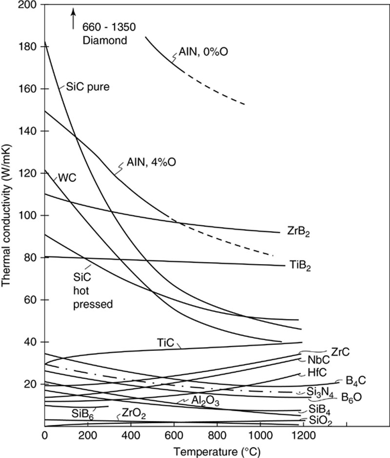
Figure 1.10 Thermal Conductivity of Ceramics Compounds. Note the Little Conductivity of Oxides Compared to Borides, Carbides, and Nitrides
Oxidation Resistance
For the selection of ceramics in an oxidizing high-temperature environment and, as hard materials, for working or even simply contacting metals, the oxidation resistance is an important criterion. Unfortunately, the data reported in the literature about the oxidation velocity, in particular about the rate constant, are very unreliable and show a large scattering range. This fact can be explained by either the variations in microstructures or by the particular additives and dopants which may change the chemical behavior of the ceramics significantly. Furthermore, the characterization treatments are usually different and yield values that are not comparable. Accordingly, Figure 1.11 represents only tendencies of the oxidation resistance of various ceramics. The most insensitive materials are silicon compounds such as silicon borides, molybdenum disilicide (MoSi2), silicon carbide, and silicon nitride. These materials form a relatively dense silica layer on the surface exposed to air preventing oxygen diffusion to the bulk material beneath. The stability of this oxidation layer being proved efficient in laboratory experiments is, however, in question if it is exposed to aggressive atmospheres containing alkaline volatiles, exposed to alkaline solutions, or removed by abrasive or impact wear. In this case, the material is consumed by continuous oxidation and removal of the newly formed oxidation layer. Another example may show that the weight gain as a measure for oxidation resistance must be evaluated with great care. Boron carbide, (not presented in Figure 1.11) does not exhibit a significant weight gain or weight loss when exposed to air. In reality, the weight gain by the formation of boron oxide layers and the weight loss due to the evaporation of boron oxide balance each other causing the recorded weight to remain almost constant up to 1000 °C until all the boron carbide is transformed to boron oxide. Transition metal borides and carbides undergo severe oxidation during the very first time of exposure followed by more or less parabolic time dependence.
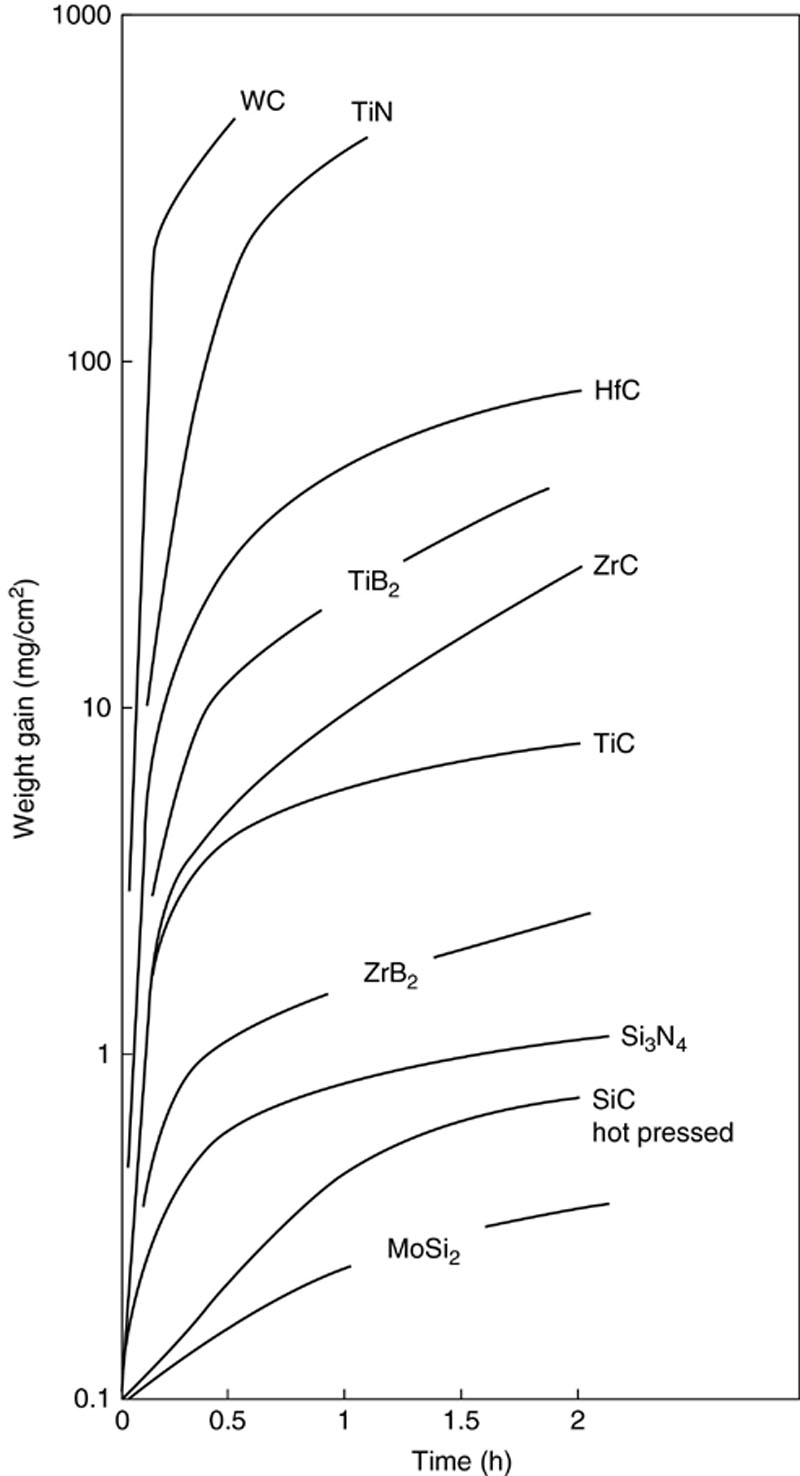
Figure 1.11 Time dependent oxidation behavior of non-oxides exposed at 1000 °c to air
Chemical Reactivity
In order to minimize chemical wear at higher temperatures, reactions between materials in contact with each other and work material must be generally excluded or at least run very slowly. This means that the materials are in a thermodynamic equilibrium throughout the expected temperature range or both materials possess a very low enthalpy of formation which is a measure of the stability of compounds. In Figure 1.12, the enthalpy of formation of some more important structural materials are shown. Accordingly, zirconia and alumina are the most stable compounds followed by titanium nitride, titanium carbide, silicon nitride when compared with hard metals: WC and Co which, as an element, has a zero enthalpy of formation by definition. According to this “figure of merit”, the hard metals are less suited for a series of applications due to their high chemical wear. If the enthalpy of formation of the contact materials are known, chemical reactions can be predicted by thermodynamic calculations. Many phase diagrams have already been assessed by experimental investigations together with computer-aided thermodynamic modeling. As an example, in Figure 1.13 the ternary system B-C-Fe is presented. The dashed line shows the considered contact between a boron carbide-based cutting tool during machining steel or a comparable wear-resistant boron carbide coating a steel. This line crosses more then six multicomponent equilibria involving iron borides and iron carbides. This means that boron carbide is not stable together with iron even below 1000 °C but decomposes to form FeB + C, FeB + Fe3C + C, or other borides being rich in iron. From the same phase diagram, it can be predicted that diamond grinding grits are partially dissolved in the iron work material forming cementite if the concentration of carbon gets high enough. This is a well-known problem from drilling steel-reinforced concrete with diamond tools.
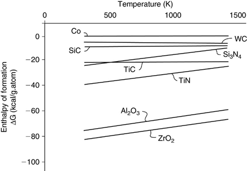
Figure 1.12 Enthalpy of formation of various hard materials
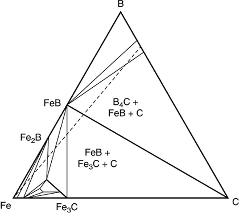
Figure 1.13 Isothermal section of the B-C-Fe system; the dashed line represents the contact between boron carbide and steel
Alumina ceramics, silicon nitride, titanium nitride, and titanium carbide react minimally with steel whereas zirconia may undergo strong chemical wear during sliding contact in spite of its high chemical stability. This is because zirconia is an excellent oxygen ion conductor and suffers therefore from a rapid oxygen transfer to the steel, i.e., zirconia is reduced and iron is oxidized. This reaction may continue to a certain critical oxygen deficiency above which zirconia degrades and forms metallic zirconium. An additional risk for cutting steel with zirconia is the adhesive interaction with manganese sulfide which may result in a build-up of the cutting edges. In contact with metals under nitrogen atmosphere, zirconia may accommodate N instead of O in the crystal lattice and therefore change its transformation behavior.
Thermal Shock Resistance
The resistance against thermal shock describes the tolerance of a material against temperature-induced stresses in the microstructure. Both the isotropy of the thermal expansion of non-cubic crystalline phases as well as the variation of thermal expansion between different phases may give rise to a stress accumulation if the material is loaded with temperature gradients. The critical parameter for thermal shock is usually given as temperature difference  TC by which a material can be quenched without significant mechanical damage, e.g., decrease of fracture strength σc For some materials, so-called R-factors are available which give figures of merits for ranking the particular materials for certain applications. The R-factors involve elastic properties like Young’s modulus (E) Poisson ratio (v), the thermal expansion coefficient (a), the thermal conductivity (λ), and the fracture toughness (K1c). The R-factors can be calculated according to the following equations:
 (1.2)
(1.2) (1.3)
(1.3) (1.4)
(1.4)Since most of the parameters are microstructure-dependent, they are more or less the critical values for ranking. The critical temperature difference TC is measured by quenching experiments using bending bars and subsequent testing of the fracture strength. In this case, additional information is given by the residual fracture strength σr even if TC is exceeded. The resistance against thermal shock is higher the larger the R-factors have been calculated or the higher the temperature difference is tolerated without decrease of strength. Table 1.4 shows calculated R-values for a series of ceramics and hard materials; this yields evidence that diamond is again the best material if the thermal conductivity is considered. As described before, fracture strength and toughness of diamond or related superhard materials are not adequately known, so these figures of merit give only a tendency. Metallically-behaving, hard materials like transition metal borides and carbides have a comparatively poor figure of merit due to their high thermal expansion and in spite of their high thermal conductivity.
Table 1.4
Thermal Properties of Ceramics
| Thermal Expansion Coefficient | Thermal Conductivity at RT | Thermal Shock Parameters | |||
| Material | αRT-1000 | λ | R1 | R2 | R3/ |
| (10−6 K−1) | (Wm−1 K−1) | (K) | (Wm−1) | (Wm−1/2) | |
| Diamond | 0.8–1.5 | 1,000–2,000 | 104 | 106 | 104 |
| Boron carbide B4C | 4.2–4.5 | 40–45 | 180 | 7,600 | 53 |
| Silicon carbide SiC | 4.5–4.8 | 60–150 | 195 | 19,500 | 211 |
| Tungsten carbide WC | 5.2–6.0 | 100–120 | 41 | 4,500 | 181 |
| Titanium carbide TiC | 7.4–7.7 | 33–35 | 58 | 2,030 | 39 |
| Titanium diboride TiB2 | 6.5–8.51 | 65–120 | 95 | 9,500 | 129 |
| Silicon nitride Si3N4 | 3.2–3.5 | 32–35 | 500 | 17,000 | 195 |
| Alumina Al2O3 | 7.2–8.6 | 27 | 129 | 3,500 | 43 |
| Zirconia ZrO2 | 8–10 | 1.7–2.2 | 220 | 400 | 7 |

Wear Resistance
If the relation between wear resistance and the factor KIc3/4 × H1/2 (compare Table 1.2) is considered, an adequate measure for ruling out wear resistant materials (and accordingly difficult to machine) and a ranking order of hard materials can be established led by diamond and cubic boron nitride (Table 1.5). The higher capability of the superhard materials is, of course, due to the extraordinary hardness and additionally to the assigned but not accurately proved high fracture resistance. They are followed by boron carbide and tungsten carbide, the first because of its high hardness, the latter because of its comparatively high toughness. The advantage of composite materials is based upon the improved fracture toughness whereas, on the other hand, the hardness can be significantly lowered by adding a softer second phase. This is, for instance, the case for Al2O3-ZrO2 composites.
Table 1.5
Abrasive Wear Resistance of Ceramics
| Material | Wear Factor Kk3/4·H1/2 |
| CBN | 59 |
| Diamond | 52 |
| B4C | 15–28 |
| WC | 24 |
| TiC | 15 |
| SiAION | 14 |
| SiC | 14 |
| Si3N4 | 12 |
| Si3N4 + TiC | 21 |
| Al2O3 + TiC | 17 |
| SiC + HfO2 | 15 |
| Al2O3 + ZrO2 | 15 |
| Al2O3 | 9 |
Consequently, these materials must be improved according to their final application as structural wear resistant material (15-18% ZrO2) or cutting material (which means higher alumina content). Again, it must be noted that both fracture toughness and hardness depend strongly on the microstructure of the component and the manufacturing parameters. Furthermore, Table 1.5 does not imply any temperature-dependent variations of the mechanical parameters given. In most cases, information about a high-temperature fracture toughness is not available anyway. Like the other ranking methods, this is also a very crude way to rule out materials.
Comparison Between Ceramics and Other Hard Materials
A comparison between the properties of hard materials as given in the preceeding tables and figures may result in the conclusion that, excluding diamond and cubic boron nitride for certain cutting and grinding operations, alumina, zirconia, silicon nitride, and silicon carbide are basically the most suitable wear resistant materials. These materials can be readily improved by suitable combinations of materials such as alumina reinforced with titanium carbide or zirconia particles due to their high hardness combined with a high fracture toughness. Figure 1.14 shows a comparison between ceramics and metallic materials concerning hardness and fracture strength. It is evident that new developments in the field of hard metals, e.g., iron-bonded TiB2, binderless tungsten carbide, and new coatings have filled the gap between super hard materials and tool steels with regard to toughness and hardness.
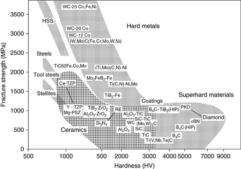
Figure 1.14 Comparison between metals, hard metals, ceramics and superhard materials in respect to hardness and strength
1.4. Microstructural reinforcement of ceramics
Fundamentals
Low-Temperature Behavior
In the class of structural ceramics, oxides, carbides, nitride, and borides are utilized. They consist of very hard crystallites that are usually held together by an amorphous grain-boundary phase. Below the softening temperasure of the glassy phase, these materials behave in a linear-elastic manner; above, softening of the glass phase, inelastic deformation and grain boundary sliding may occur. Below the softening temperature, mechanically stresssed ceramics may fail by the following mechanisms:
(a) rapid low-strain fracture,
(b) subcritical crack propagation including stress corrosion, and
(c) mechanical fatigue.
All of these failure modes are triggered by process-induced microstructural flaws or defects that result from shaping or load application. Because of the linear-elastic behavior, the rapid low-strain fracture of ceramics can be modeled with methods of linear-elastic fracture mechanics. From the Griffith equation (1.1), it follows that the strength must increase either when the fracture toughness is increased or when the size of the fracture-initiating flaw is reduced. From these two possibilities, the basic trends toward developing improved structural ceramics is pursued. The enhancement of fracture toughness is often referred to as “microstructural strengthening,” and the reduction of flaw size is referred to as “defect-controlling manufacturing methods.”
In metals and alloys, strength and toughness tend to move in opposite directions, i.e., increasing the toughness decreases the strength. Of course, it is possible to overcome this trend in metals by hardening the grain boundaries or by increasing the purity. On the other hand, in ceramics an increase in toughness is translated directly into an improvement in strength [equation (1.1)]. The toughness-enhancing measures have the additional advantage that in the previously elastic ceramic, minor inelastic processes (quasi-ductility) are possible. Differing from the case of metals, the source of this deformation is not dislocation motion but rather phase transformation (transformation-induced toughening) or the formation of microcracks (micro-crack-induced toughening).
The second approach to improving the strength of ceramics is to reduce the flaw size. This is accomplished chiefly by the consistent improvement of all steps in ceramic processing. It is difficult to eliminate or to reduce existing defects in size during subsequent processing steps (e.g., sintering). As a rule, such defects tend to increase in size. Controlled-defect processing requires fine powders with a favorable particle size and shape distribution, a uniform spatial distribution of additives within the powder, optimization of the compaction process, and the possibility of eliminating, by destructive or nondestructive methods, bodies that contain large defects.
Another interesting consequence of equation (1.1) is that the strength of ceramics can only be described by statistical methods and, furthermore, is dependent on specimen size. For the most part, the largest defect in a given specimen is also the one that triggers failure, yet in two specimen of identical appearance, the size of the largest defect is never the same. Therefore, it follows from equation (1.1) that the strength of the two specimen cannot be exactly the same, so that statements about the strength of ceramics can only be related by a distribution function. An example of such a function is the Weibull distribution, as shown in Figure 1.15 and equation (1.2). Here the probability, P, of failure is plotted against the applied stress, σ. At low loads, the probability of failure is small; at high loads, it approaches unity. The data points show that the Weibull distribution is a good approximation.
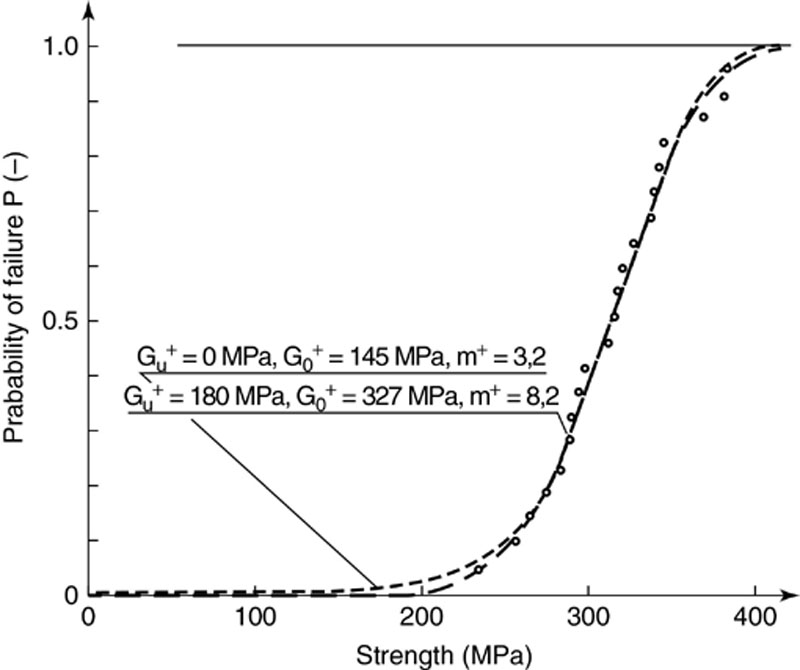
Figure 1.15 Probability of failure of a ceramic. points: measurement, dashed line two-parameter weibull-function, continuous line: three-parameter weibull function (after Danzer, 1988)
The origin of the previously-mentioned size dependence of the fracture strength is similarly based. Because of the higher specimen volume, the probability of finding a large fracture-triggering flaw is higher in a large specimen than in a small one. Hence, the failure probability of a large specimen is higher for a given stress. For an expected failure probability, the permissible stress is lower. These facts are expressed in the Weibull distribution in the form:
 (1.5)
(1.5)The failure probability P is highly sensitive to the Weibull exponent m, especially in the technologically interesting range of low stresses. It has been shown that the Weibull exponent is a descriptor of the size distribution of flaws and, as such, can be determined ceramographically. When in a specimen of volume Vo the stress reaches the characteristic value σo the probability of failure becomes l/e. The characteristic volume Vo is usually set equal to 1 mm3.
The Weibull distribution is frequently used to predict the failure probability in mass-produced components. The risks inherent in this procedure can be assessed with the following example [1].
Consider a part for which a failure rate of 10-5, i.e., one part in 100,000, is acceptable on economic grounds. To keep costs down, the Weibull distribution is held to a limited sample of usually less than 100 parts. With 100 samples the Weibull distribution is defined in the range P = 0.01 (1%) to 0.99 (99%) so that the experimental distribution has to be extrapolated over three orders of magnitude to obtain valid information on the stress to which the part can be subjected. While the Weibull distribution of equation 1.5 is a possible function to describe the strength of brittle materials, it is by no means the only one. This can be seen in Figure 1.16 where the curves of Figure 1.15 are re-plotted on a semi-logarithmic scale [1]. It is obvious that the three-parameter Weibull distribution, although it fits the experimental data too, deviates considerably in the extrapolated range. Therefore, extrapolation makes sense only when additional information concerning size and distribution of defects is available. Such information can be extracted from process data, nondestructive and destructive testing (e.g., ultrasonic, x-ray, and/or proof tests), and from ceramographic characterization methods. The importance of proof tests is visualized in Figure 1.17 showing the applied stress distribution loading a ceramic part during service and the strength distribution of a manufacturing batch of this particular part. Ideally, both Gaussian distributions should be clearly separated from each in order to prevent the weakest ceramic part from rupture due to the highest possible load. This is accomplished either by shifting the medium fracture strength to values as high as possible, still running the risk of providing parts with a certain probability of an extremely low strength, or by cutting off the low-strength part from the distribution by subjecting each part to a certain test load above the maximum applied stress and providing only those parts which have survived.
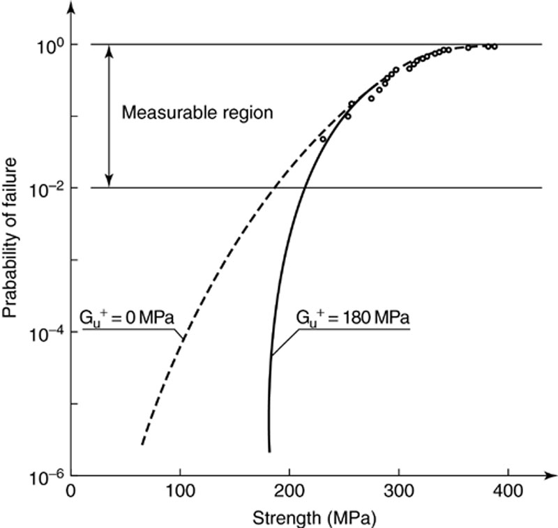
Figure 1.16 Extrapolation of the weibull distributions of Figure 1.15 for small failure probabilities (after Danzer, 1988)
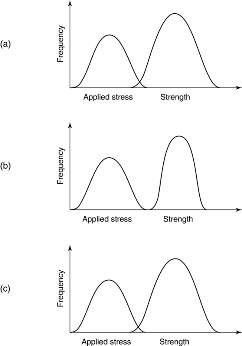
Figure 1.17 Applied stress profile in service and strength distribution of a manufacturing series of ceramic parts
(a) Risk of failure due to distribution overlap
(b) Curve separation by improved manufacturing (higher reliability)
(c) Curve overlap truncated by proof testing
The low-temperature failure modes of subcritical crack propagation and fatigue are also triggered by the aforementioned defects, so that the familiar statistical problems are encountered. Obviously, this mechanism is affected by the volume fraction, distribution, and composition of the grain boundary phase as described before.
High-Temperature Behavior
At temperatures above the softening temperature of the grain boundary phase, permanent inelastic deformation (creep) occurs by grain bound-any sliding or creep pore formation and rupture. Therefore, the strength of the material is time-dependent and because of the temperature dependence of grain boundary sliding, also temperature-dependent. These basic mechanisms of failure are schematically summarized in Figure 1.18. Additional causes of failure at high temperatures are oxidation and corrosion as already mentioned. The failure mechanisms discussed in the previous section are still operative at high temperatures, but they are of less significance. The high-temperature properties of ceramics can be expected to improve with all measures that inhibit grain boundary sliding. Primarily, this requires the utilization of materials that contain little or no glassy phase in the grain boundaries. By a judicious choice of composition and with the help of a suitable annealing procedure, the glass can be crystallized, resulting in a significant reduction of grain boundary sliding. This is the usual procedure for the high-temperature strengthening of silicon nitride ceramics which need a liquid phase to aid sintering. If the densification is terminated, the especially doped glassy phases are crystallized by an annealing treatment. A further possibility is the creation of roughened grain boundaries that interlock as grain boundary sliding progresses or the in-situ precipitation of particles from supersaturated solid solutions that grow across grain boundaries.
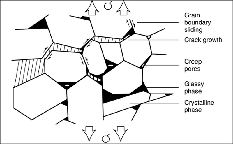
Figure 1.18 Ht-deformation of ceramics containing glassy phases
Strengthening Mechanisms and Microstructure
The fracture strength of ceramics can be improved only by mechanisms that influence crack propagation. Whereas in metals the high toughness is obtained by plastic deformation within a zone ahead of the crack tip (K1c = 20-200 MPam1/2), the tensile stress in an unreinforced ceramic is entirely concentrated in a small volume ahead of the crack tip. One goal of reinforcement is to deflect the crack from its straight linear path, with several resulting positive effects. On the one hand, the fracture surface is increased; on the other, the crack is reoriented in the field of the applied stress. Further energy-consuming processes occur, such as crack flank attrition and crack bridging. All of these mechanisms reduce the stress intensity at the crack tip, and they are referred to as crack shielding. Another method of increasing the toughness is transformation toughening in which quasi-plastic deformation is induced in the process zone surrounding the crack tip by a martensitic transformation in an internal phase. This introduces compressive stresses and microcracks that significantly reduce the stress at the crack tip. With the latter method, it has been possible to obtain the highest toughness increments achievable to date (up to 20 Mpam1/2). The various strengthening mechanisms are explained in greater detail in the following sections.
Dispersion Strengthening
In dispersion strengthening, the toughening effect of dispersed particles is exploited [2]. For the most part, it operates by crack deflection. A special case is whisker strengthening in which several mechanisms operate at the same time, as will be shown. The dispersed particles introduce elastic inhomogeneities into the matrix material to influence the propagation of nearby cracks. Dispersion strengthening requires that the mechanical properties of the second phase differ from those of the matrix. Thus, the elastic modulus of the particles should exceed that of the matrix, the thermal expansion should differ from that of the matrix, the strength of the particle should exceed that of the matrix, and the interfacial strength should be smaller than that of the matrix.
After sintering, the material contains misfit stresses caused by the difference in thermal contraction between the matrix and the dispersed particles during cooling. Figure 1.19 shows schematically the case of thermal expansion coefficients α of the particles that are smaller than, equal to, or greater than that of the matrix. For idealized particle morphologies and αparticle < αmatrix, one obtains radial compressive stresses and tangential stresses that are tensile. A growing crack tends to run normal to the tensile stress because it opens the crack. In a sense, the crack is attracted by the particle and spends a short time normal to the particle/matrix interface. If the particle cannot be split by the crack, the energy must be increased to make it run around the particle. In the case αparticle = αmatrix there are ideally no stresses at the particle/matrix interface. However, the interface acts as a crack deflector because of the difference in elastic moduli between particle and matrix. When Ematrix < Eparticles the elastic strain is greater in the matrix than in the particle (Ematrix < Eparticles) so that part of the crack-forming tensile stress is transmitted to the particle. Consequently, tensile stresses are concentrated at the particle/matrix interface and can lead to crack deflection.
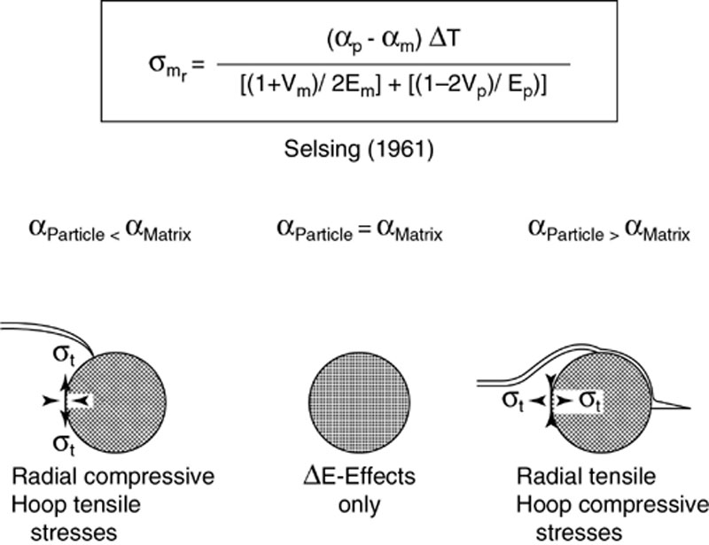
Figure 1.19 Influence of the thermal misfit strain on crack propagation: crack arrest and crack deflection at dispersed particles
The third case αparticles > αmatrix leads to radial tensile stresses and tangential compressive stresses during cooling. The tensile stresses are perpendicular to the particle/matrix interface and introduce a crack that moves along the interface. The energy consuming processes consist of (a) the increased crack surface in the interface and (b) the increased energy required to exit the interface and re-enter the matrix (Figure 1.19). Occasionally, this effect can be observed during grinding and polishing when in multiphase ceramics the grains of one particular phase are preferentially pulled out. Figure 1.20 shows the resulting crack path for a SiC/TiC and SiC/TiB2 composite, respectively. If the thermal misfit stresses get close to the critical rupture stress for the grain boundaries, they may give rise to strain-induced cracking if additional loads are applied by the grinding and polishing treatment. Consequently, particular grains may be liberated by circumferential cracks and can be pulled out.
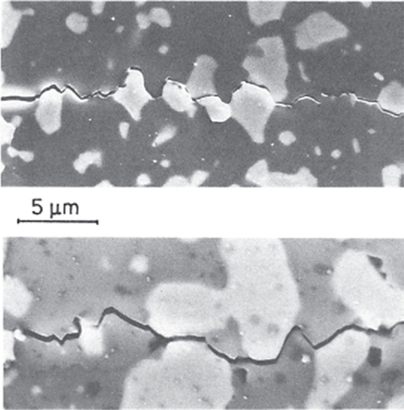
Figure 1.20 Non-planar crack propagation in Sic/ti (Top) and Tic/tib2 composities
Ceramics in which the crack deflection is frequently 90° to the direction of the main crack show the additional strengthening effect of crack flank friction. When opposite sides of the fracture surface are locked together, shear forces are generated which may create additional crack systems. When individual particles are neither bypassed nor cleaved, crack bridging occurs (Figure 1.21). Crack bridging by a highly viscous glass phase is frequently found in ceramics with sinter additives at high temperatures.
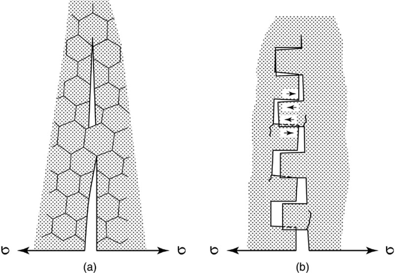
Figure 1.21 Crack flank effects:
(a) Crack wake friction and interlocking crack surfaces
(b) Crack bridging
For optimal strengthening by crack deflection, geometrical factors are essential in addition to the properties of matrix and particles. Since the misfit stresses at the particle/matrix interface decrease in the matrix with R−3, the volume fraction and homogeneity of the dispersion are important. To prevent catastrophic crack propagation, a minimum distance between the particles must be maintained.
Theoretical analyses of fracture in dispersion-strengthened ceramics have shown that the amount of crack deflection and effective strengthening also depends on the shape of the included particles [3]. It became evident that spherical particles already cause a definite improvement of the mechanical properties, but platelets are significantly better; the greatest strengthening effects are achieved with fibers. A precondition for maximum exploitation of the predicted behavior is that the particle orientation be random for random loading. For axial loads, they are oriented one- or two-dimensionally perpendicular to the applied force (Figure 1.22). Since conventional processing usually leads to deformation textures, hot pressing by axial compression generally causes the powder particles to orient perpendicular to the hot-pressing direction; both random and preferred orientation are not always easily attained.
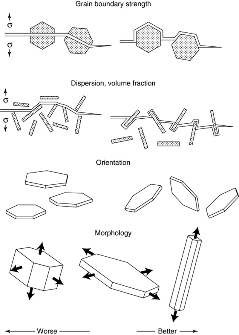
Figure 1.22 Preconditions for an effective microstructural toughening of composites
The desired ideal shape of a one-dimensionally elongated particle is found in whiskers or short fibers. By adding high-strength, single-crystal whiskers or polycrystalline fibers, improvement of high-temperature strength, fracture toughness, thermal shock resistance, and reliability of brittle ceramics is achieved. In addition to the aforementioned strengthening mechanisms of crack deflection, proper selection of fiber, whisker, and matrix materials can further assist with crack deflection, load transfer, pull-out, and matrix pre-stressing.
Load transfer from ceramic matrix to whisker presupposes a higher elastic modulus in the whisker: a condition that is achievable even in single-phase materials because of the elastic isotropy of the single-crystalline whisker. Because of the elastic stiffness of the whisker, a portion of the applied stresses is transferred to the fiber (Figure 1.23). This releases the stresses in the matrix.
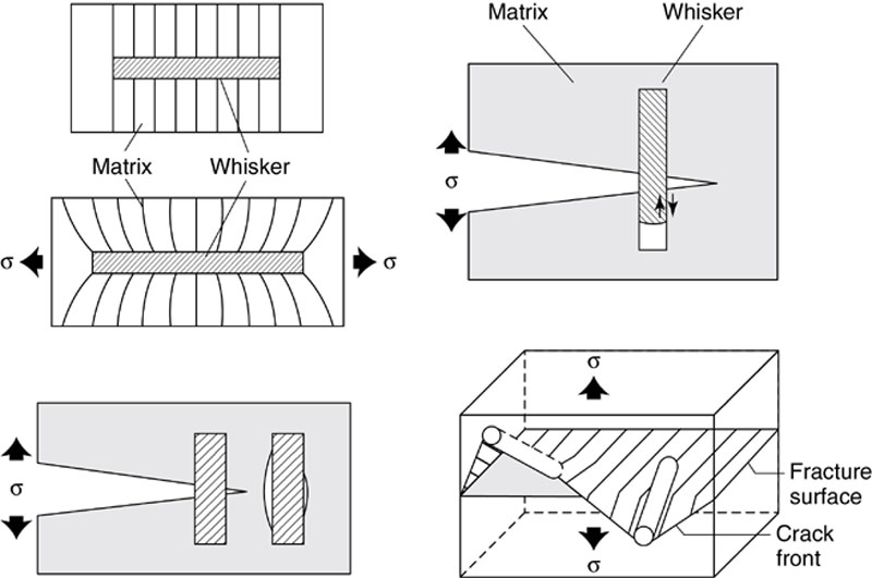
Figure 1.23 Mechanisms of Whisker-reinforcement (Courtesy, Hoffman, Karlsruhe)
When fibers are pulled out of the matrix during crack growth, an additional significant mechanism of high-energy consumption is involved. During fracture, the fiber tips may remain clamped in the opposing crack flanks and are first strained elastically. Ideally, the whisker does not fracture but is pulled out of the matrix. Depending upon the properties of the interface, this occurs with increasing or decreasing friction. This type of crack bridging by fibers and/or the pull-out accompanied by friction deflects a large fraction of the stresses in the crack flank region, thus relieving the stresses at the crack tip. Although the pull-out is the most effective of all strengthening mechanisms, it is rarely observed in real fracture surfaces so that its actual contribution to the strengthening of ceramics is small.
The principle of matrix pre-stressing is based on differences in the thermal expansion coefficients of fiber and matrix (αwhisker αmatrix) and is similar to crack deflection. Because of the greater contraction of the whiskers during cooling, the whisker/matrix interface shows radial tensile stresses and tangential compressive stresses in the matrix itself. The effect of matrix pre-stressing is comparable to the behavior of pre-stressed concrete where the brittle mixture of cement and gravel is kept under compression by pre-stressed reinforcing bars.
There are numerous examples of dispersion-strengthened ceramics. This includes such material combinations as Al2O3-TiC, Al2O3-spinel, ZrO2-A12O3, SiC-TiC, and B4C-TiB2 (Table 1.3). A significant jump in mechanical properties has been attained by the inclusion of SiC-whiskers (Figure 1.24) [4]. In matrix ceramics (e.g., Si3N4, ZrO2) with an inherently high toughness, this can be improved further at the expense of overall strength. Between 1985 and 1992, silicon carbide-whisker reinforced oxides have been successfully developed for cutting tools and structural applications. However, the activities in fiber-reinforced materials decreased generally when it became evident that ceramic fibers could be carcinogenic. In Europe, production of whisker-reinforced materials stopped but some Swedish companies continued until the beginning of the ‘90s to provide this high-performance materials to the world market. Besides the potential carcinogenic effects of the whiskers, the risk of introducing large defects into the ceramics with supercritical length or whisker agglomerates could cause a tremendous decrease in strength; this retarded the enthusiasm.
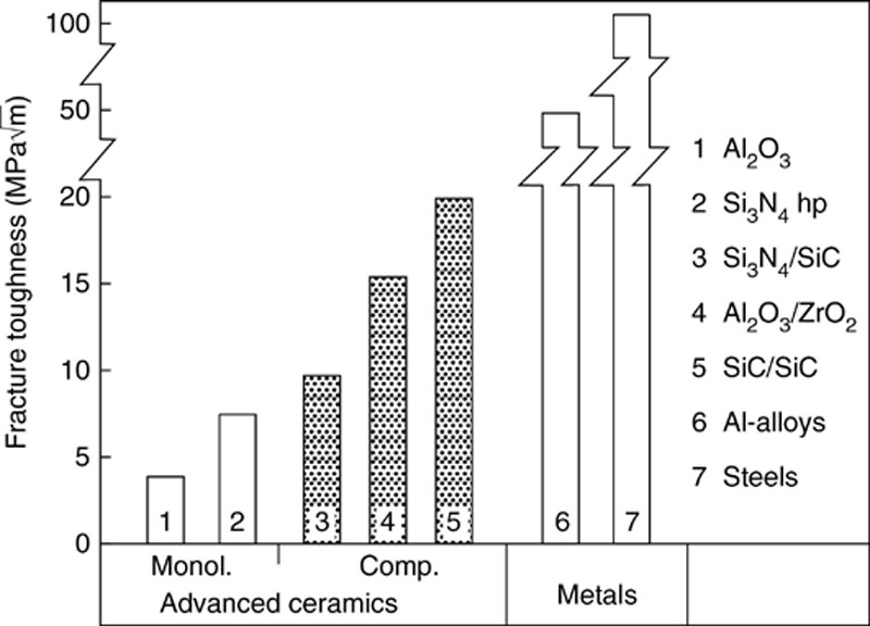
Figure 1.24 Toughness increase by Whisker reinforcement compared to non-toughened monoliths (1 and 2) and transformation toughened alumina (4) (Courtesy, Greil, Erlangen)
Microcrack Reinforcement
A further possibility of reducing the stress concentration in the crack tip is found in the deliberate introduction of a large number of small cracks. This so-called microcrack reinforcement operates by a judicious choice of phase combinations, morphology, and dispersed particles so that the particles partially separate from the matrix when subjected to an additional external load. At the matrix/particle interface, cracks on the order of tens to hundreds of nanometers are formed. Such microcracks are found in the so-called process zone along the crack flanks some distance ahead of the crack tip because the tensile stresses emanating from the crack tip extend into the undisturbed microstructure [5].
When the load is further increased, the favorably oriented micro-cracks, of which there are hundreds, grow by a fraction of their original length and thereby reduce the peak concentrations. The stress concentration at the tip of a macrocrack essentially spreads to a multiplicity of small cracks. The material behaves in an elastoplastic manner because the microcrack formation is partially reversible upon load removal.
This reinforcement strategy is not without risk. Unless the misfit stresses are optimized, the presence of excessively high local stresses can lead to spontaneous formation of microcracks to the point of coalescence so that the mechanical properties of the material are severely affected. A macrocrack is enhanced by having to provide only the additional energy needed for microcrack coalescence before catastrophic failure occurs. In Figure 1.25 [5], the dependence of fracture toughness on internal stresses is shown schematically. Below a critical stress (σic), no microcracks are formed even under an applied load so that no interaction takes place between macrocrack and microcracks and no increase in toughness is observed; however, above σic, the formation of the process zone around the main crack starts. By superposition of the internal and applied stresses, the formation of stress-induced microcracks away from the crack tip becomes possible. The shielding of the principal crack from the external load leads to a significant increase in toughness. The maximum toughness is reached at σc when the stresses are high enough to induce spontaneous microcrack formation. Further increases of toughness in this region are conceivable when existing microcracks split or branch out. Then the principal crack repeatedly changes its course and may show multiple branching. Because of the deflection of the stress field and the increase in fracture energy associated with the increased fracture surface, a high-energy consumption is still present. At higher internal stresses, the microcracks begin to interact and may accelerate the propagation of a macrocrack under an applied load. Therefore, it is the goal of materials development to find an optimum increase in toughness in the upper third of the ascending branch of the curve in Figure 1.25 by exploiting the micro-structure and selecting phases with suitable thermal expansion coefficients.
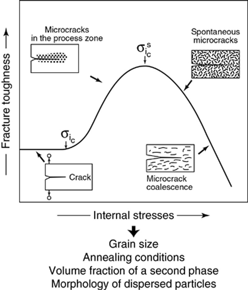
Figure 1.25 Microcrack formation and influence on fracture toughness
Reinforcement by microcracks has proven itself especially in materials sensitive to thermal shock. In materials that are subjected to reversible mechanical stresses, it may, however, lead to subcritical crack growth, of which little is known, or to mechanical fatigue. Figure 1.26 presents a TEM-micrograph of a ZrB2/ZrO2 composite where radial microcracks have been originated from the transformation of tetragonal zirconia to the monoclinic modification.
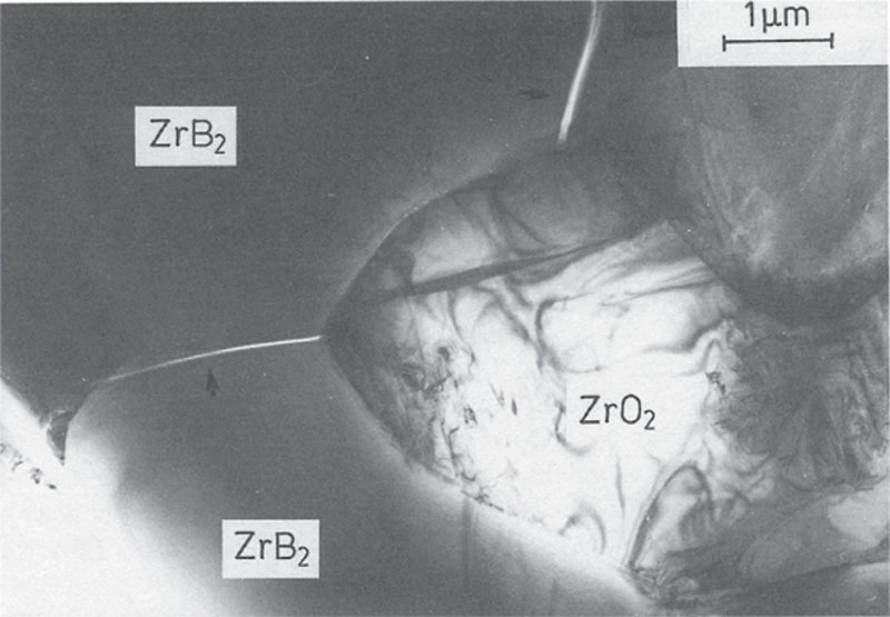
Figure 1.26 Radial microcracks origination from T → m transformed zirconia; tern-micrograph
Transformation Toughening
Transformation toughening is the deliberate exploitation of a phase transformation of dispersed particles in a ceramic matrix [6,7]. It is a prerequisite that the low temperature phase of the material to be transformed has a lower density, i.e., is a larger volume than the high-temperature modification. A condition for the matrix is that the stresses accompanying the transformation be relaxed very slowly or not at all. Among the many materials that exhibit such a transformation, ZrO2 has proven to be especially suitable.
Zirconia crystallizes in three modifications. Below the melting point near 2,700 °C, the cubic (c) phase with the calcium fluoride structure exists that transforms to a tetragonally (t) distorted CaF2 structure at 2,370 °C. Below 1,170 °C, a further distortion, accompanied by a volume expansion of 3–5%, leads to a monoclinic (m) modification. This transformation, tetragonal to monoclinic, which is mainly utilized, is martensitic, i.e., diffusionless and reversible. During the modification change, the tetragonal structure is sheared by 9° while the a and b axes are stretched. This phase transformation is sudden, but the tetragonal high-temperature modification is capable of being metastably undercooled. Therefore, t-ZrO2 can be dispersed in a ceramic matrix such as Al2O3 so that the work of volume expansion has to be performed against the surrounding matrix. The activation energy of the transformation is obtained from the undercooling, and the nucleation energy increases with decreasing size of the ZrO2 particles. The activation energy can also be gained from the stored elastic energy that results from the misfit between particle and matrix or from the strains ahead of a macrocrack.
Optimal utilization of the martensitic transformation of ZrO2 requires that it take place in a controlled fashion. This is accomplished by control of the grain size distribution and by selection of a matrix material with a lower coefficient of thermal expansion. This generates radial tensile stresses at the particle/matrix interface that adjust the activation energy of the transformation precisely; the tetragonal modification is retained at room temperature but can be transformed under the influence of an applied stress. Furthermore, ZrO2 can be stabilized chemically by adding MgO, CaO, or Y2O3. Since magnesium, calcium, and yttrium have an ionic radius near that of zirconium, they are introduced into the ZrO2 lattice by ionic diffusion and impede the t → m transformation by creating oxygen vacancies. Such stabilizers are required especially in pure ZrO2 single phase ceramics or in composites with matrices having a significantly lower coefficient of thermal expansion than zirconia.
Three mechanisms are responsible for the absorption of fracture energy in transformation strengthening (Figure 1.27) [6]:
(a) stress-induced transformation during loading,
(b) microcrack formation, and
(c) crack deflection.
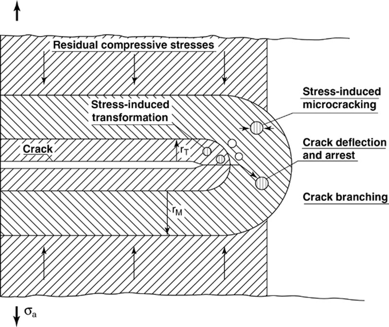
Figure 1.27 Schematic representation of the reinforcing mechanisms in zirconia ceramics (Courtesy, Claussen, Hamburg)
The stress-induced transformation is essentially based on a crack shielding effect resulting from the volume and shape changes of the ZrO2. The fracture energy is consumed by the work of transformation, and tensile stresses in the region of the crack tip are removed by the compressive stresses accompanying the volume increase of the ZrO2; in other words, the crack is partially closed again. Such process zones in which transformed monoclinic ZrO2 is found can be observed by electron microscopy in the crack flanks or in the region of the crack tip.
An additional result of the stress-induced transformation is the production of permanent surface compressive stresses when the transformation is deliberately introduced in the surface region of a material by grinding or sand blasting. The resulting compressive stresses prevent crack penetration in the surface region which leads to increased strength and thermal shock resistance.
If the ZrO2 is not stabilized in the tetragonal modification during fabrication, (spontaneously transformed) or if the strain-induced transformation already occurred, then the formation of radial microcracks is conceivable around such transformed particles as a result of the volume expansion (Figure 1.27). The energy of an externally-induced macrocrack is absorbed by the same mechanism as described in microcrack reinforcement: the extension of the strain-induced microcracks and the associated crack branching. A reduction in fracture energy can also be attained by forcing a transcrystalline crack in the matrix to move around the ZrO2 particle (intercrystalline fracture). For example, a tetragonal ZrO2 crystallite, because of its thermal mismatch against Al2O3, generates radial tensile stresses; a monoclinic ZrO2 generates tangential tensile stresses so that a crack bypasses a tetragonal particle and cuts through a monoclinic one in a transcrystalline way. The aforementioned strengthening mechanisms can be simultaneously active. The most significant is undoubtedly the stress-induced transformation.
Three fundamentally different types of transformation-strengthened ceramics can be accordingly deduced:
• Partially stabilized zirconia (PSZ) in which tetragonal ZrO2 particles are coherent with cubic ZrO2. It is obtained by chemically doping the material with MgO forming so-called MgO-PSZ.
• Tetragonal zirconia polycrystals (TZP) consisting of an extremely fine-grained (<1 μm) tetragonal matrix. This is chemically stabilized with Y2O3. The materials exhibit transverse bending strengths in excess of 2,000 MPa that have not been attained by any other ceramic. This is also the group of materials that has achieved the highest fracture toughness (k.c. up to 20 MPa m−−√  ) if stabilized with ceria.
• Ceramics composites in which tetragonal or monoclinic ZrO2 particles are dispersed: ZrO2-strengthened Al2O3 (ZTA), mullite (ZTM), spinel (ZTS), cordierite, titanium diboride, and others.
Because of these properties and also because of the analogy to the crack tip plasticity observed in metals, such materials are often referred to as “ductile ceramics”; the mechanisms involved are in no way comparable to plastic deformation in metals. Examples of the improvement of mechanical properties by ZrO2 addition are shown in Figure 1.28 and listed in Table 1.6.
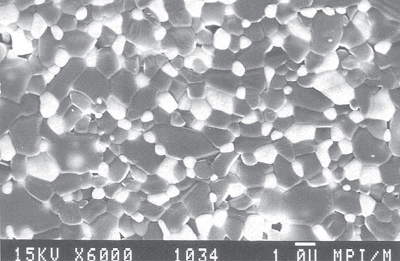
Figure 1.28 Typical microstructure of a zirconia-toughened alumina composite (Courtesy, Claussen and Schubert)
Table 1.6
Properties of Transformation-Toughened Ceramics
| Matrix | Vol.% ZrO2 | Tetragonal Fraction, Vol.-% | KIC Mpa m | KIC - K0 K0 | σF MPa | σF - σ0, % σ0 | Remarks |
| A12O3 | 15 | 20 | 9.6 | +85 | 500 | −10 | Hot-pressed. (HP) |
| A12O3 | 16 | 100 | 15.0 | +270 | 1200 | +300 | HP sol-gel-powder |
| A12O3 | 7.5 | 95 | 6.8 | +55 | 600 | +30 | Sintered, sol-gel-P |
| Spinel | 17.5 | 50 | 4.6 | +140 | 500 | +150 | HP |
| Mullite | 23 | 30 | 4.8 | +60 | 400 | +35 | Reaction sintered |
| Mullite | 23 | 80 | Reaction sintered | ||||
| ZnO | 36 | 0 | 3.3 | +95 | n.d. | n.d. | HP |
| Si3N4 | 25 | 30 cub/70 mon | 8.5 | +50 | 950 | +45 | HP, SiAION 10 |
| Si3N4 | 10 | 30 cub/60 mon. | 7.2 | +30 | 700 | +15 | HP, SAION 1 |
| SiC | 5.5 EM2 | 0 | 6.7 | +25 | n.d. | n.d. | HP (+Mullite) |
| Mg-HZ | 60% cub. | 40 | 9.0 | +260 | 600 | +140 | 3.4 wt.% MgO |
| Ca-PSZ | 50% cub. | 50 | 6.6 | +165 | 650 | +165 | 3.3 wt.% CaO |
| Y-PSZ | 20% cub. | 80 | 6.4 | +155 | 650 | +165 | 2 wt.% Y2O3 |

n.d. = not determined.
High-Temperature Strengthening
In sialons, silicon nitride, and silicon carbide ceramics, high-temperature properties are impaired by the presence of intergranular phases. Above the softening temperature of the grain boundary phase, permanent inelastic deformation may occur by grain boundary sliding glass phases. As a result, the strength becomes dependent on temperature and load time and additional failure modes of oxidation and stress corrosion are encountered. A strategy to improve the creep resistance, therefore, is to avoid such glassy phases; on the other hand, they are needed in the sinter process as a liquid that transports matter quickly and supports densification. One feasible method of high-temperature strengthening, in addition to reducing the added glass originators and oxygen impurity to an acceptable minimum, is to crystallize such residual molten phases by devitrification subsequent to the densification process [8].
To crystallize the glass phase, one must know its composition so that further additives can be included to change its composition to the stoichiometry of a crystalline phase. The phase to be crystallized should satisfy the following conditions:
• High symmetry,
• No anisotropic grain growth,
• High nucleation rate,
• Low growth rate,
• No segregation of impurities ahead of the crystallization front, and
• Specific volume similar to that of the glassy phase.
The devitrification process follows the ceramic densification and consists of a complicated anneal in the temperature range of maximum nucleation and minimum growth.
Devitrification of the glass phase leads to a stiffening of the structure at high temperatures. Viscous flow and/or grain boundary sliding can thereby be reduced to a tolerable level. In Figure 1.29, the high-temperature bend strength is shown for a silicon nitride ceramic with and without a crystallized glass phase. It is obvious that the drop in strength above 1000 °C is arrested. Similar sintering procedures with glassy phases and subsequent annealing have been recently applied to silicon carbide (SiC) where also A12O3 and Y2O3 are used to initiate liquid phase sintering followed by yttria-alumina-garnet formation.
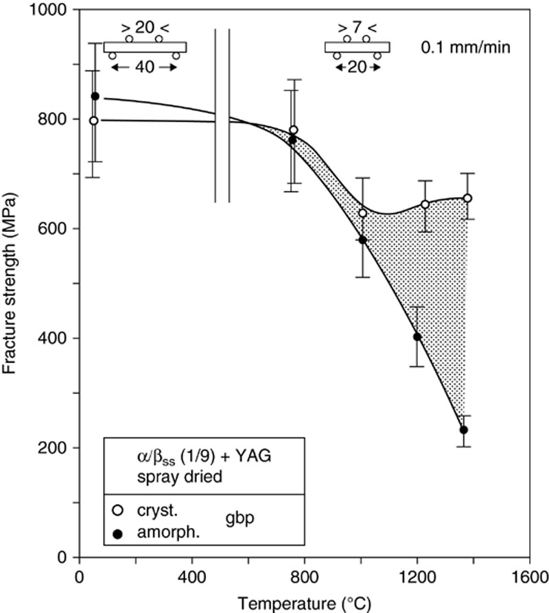
Figure 1.29 High temperature bending strength of silicon nitride ceramics with amorphous and crystalline grain boundary phases (Courtesy, Greil, Erlangen)
Another possibility to prevent high-temperature deformation is to create an interlocking microstructure by the in-situ growth of elongated particles. Figure 1.30 presents a plasma etched microstructure of a silicon nitride ceramic in which the nuclei and the growing steps of silicon nitride needles in the liquid phase can be recognized.
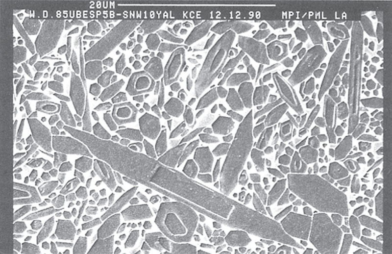
Figure 1.30 Strengthening against creep by the formation of in-situ grown elongated silicon nitride particles, plasma-etched section (Courtesy, Hoffmann, Karlsruhe)
Fracture-Producing Defects
To improve the strength of brittle ceramics, the Griffith equation (1.1) suggests a scheme in addition to the deliberate introduction of multiphase materials and optimum microstructures [9,10]. As mentioned before, the critical defect size enters the equation that indicates the maximum allowable dimensions of a microstructural defect, such as pores, inclusions, agglomerates, or giant grains, before it triggers fracture under an applied load. The goal of the increase in toughness is to increase the tolerance of the material towards such structural defects. Ideally, the ceramic should be tough enough so that defects with dimensions on the order of 1 mm can readily be ignored. Figure 1.31 shows a diagram representing the Griffith Equation by combining the ultimate rupture stress due to a critical flaw size with the value of fracture toughness of that material. In other words, the area beneath each of the “isotoughness” lines represents the stress level tolerated by a test piece with microstructural inhomogeneities being smaller than the critical flaw size.
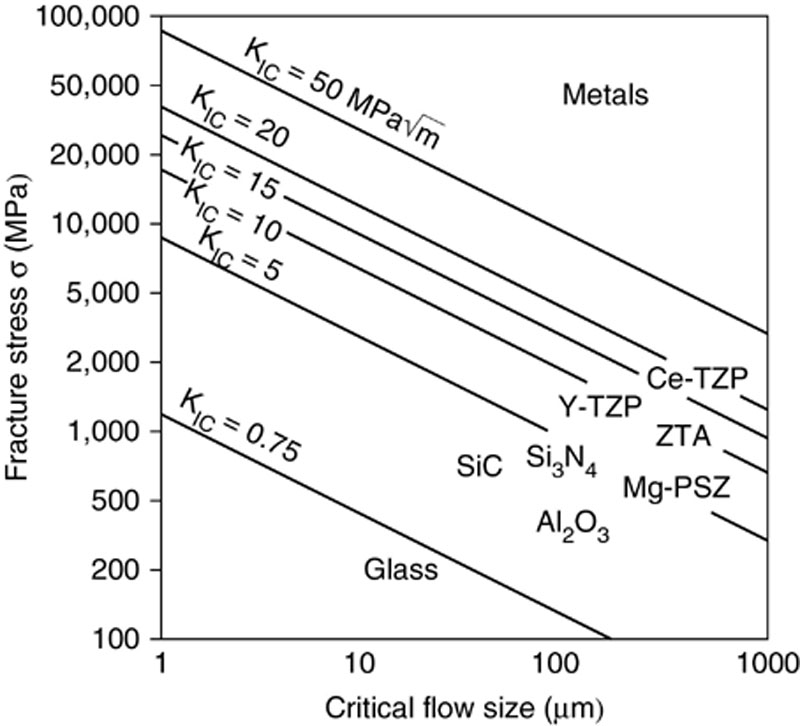
Figure 1.31 Principal dependence of failure stress from critical flaw size for different fracture toughness values
However, not only are the absolute dimensions of a microstructural defect important but also the defect concentration in a ceramic component. The distribution function of defect size and frequency determine the fracture statistics, i.e., the probability that a work piece will fail under a given load. In effect, one measures the bend strength or tensile strength of specimen and attempts to extrapolate from the comparatively small test volume to larger components or greater numbers of pieces.
Conditions leading to the coarsest microstructural defects are created as early as the powder production and preparation stage. Mechanical and chemical impurities caused by careless work, concentration gradients caused by the inhomogeneous distribution of sintering additives, or local density variations based on agglomerates are the consequences of improper powder preparation methods and cannot be eliminated by subsequent sintering or hot pressing. On the contrary, such inhomogeneities are coarsened during heat treatment because of the differing shrinkage rates during sintering: regions of high density in the powder or high concentration in the additive shrink faster and pull away from the less densely packed particles of the compact. This results in large pores or pore channels that are not readily removed even by hot isostatic pressing. Inclusions of organic matter, such as fibers, flakes of skin, or dust burn-off during sintering, leave a void that is also difficult to densify. Figure 1.32a–d shows examples of typical fracture-causing defects.
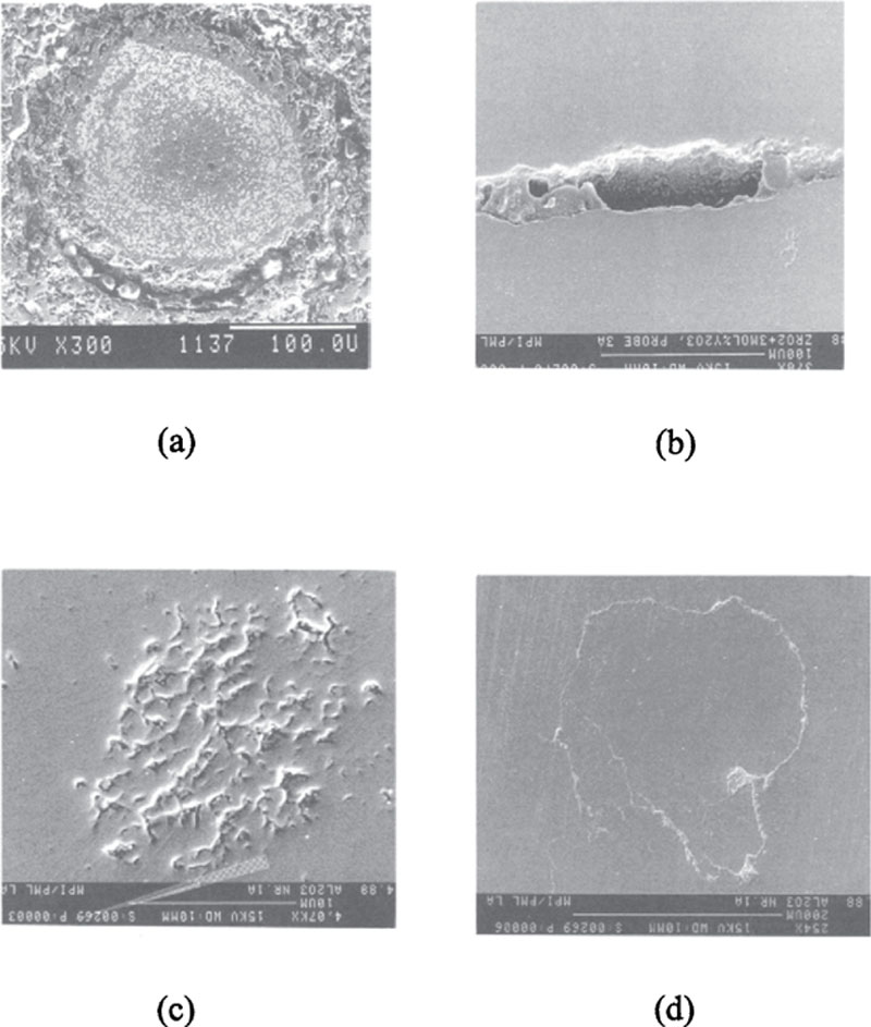
Figure 1.32 Processing-derived strength-controlling defects
(a) Wc/tib2 agglomerate in fine grained matrix with a circumferential crack
(b) Flat Pore in 3y-tzp, burnt organic compound
(c) Low-density agglomerate in alumina
(d) Agglomerate in alumina with contaminated surface
Examples of other process-related defects that originate in a later stage of powder preparation are pressing defects: variations in density caused by an uneven pressure distribution in the die, or machining defects: grinding marks or surface rupture due to fatigue. In the sintering process, the condition of the grain boundaries and triple points as well as the grain size are effective. Figure 1.33 shows qualitatively the frequency distribution of such defects as a function of their size. It is obvious that three defect populations exist. The most unproblematic defects are the micro-structure-related ones, such as grain boundaries, triple points, and crystallites that represent the largest fraction of defects. With respect to size, they usually remain sub-critical, and the only exceptions are giant grains that may grow to several 100 μm in size. The second population, with a maximum around 10-20 μm, are agglomerates, chemical impurities, and inorganic impurities resulting from cross-contamination by other powder species. Agglomerates, in particular, may extend into the critical range of 200-500 μm and thereby represent a significant cause of failure.
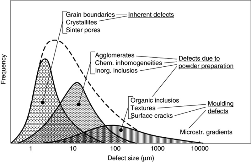
Figure 1.33 Frequency/size distribution of microstructure-immanent and process-derived flaws
The least frequent but dimensionally most hazardous defects are organic particles, pressing defects, and machining defects that may become several millimeters large and result in a probability of fracture approaching certainty. One must therefore avoid the relatively small number of large defects or detect them early by materials testing. In that sense, the bend test and tension test become a metallographic method of characterizing the micro-structure.
As a result of the even tighter requirements, the development of improved production processes has aimed at the powder purity (total metallic impurities <0.1 wt.%), on a reduction in particle size (<1 μm, preferably <100 nm), and well-defined alloy compositions in powders of high chemical homogeneity. Furthermore, controlled surface conditions of the powders, such as surface purity, agglomeration behavior, and rheological behavior are important factors in the shaping processes. Novel powder production methods that provide such well-defined powders are colloidal processes as well as reaction processing in which some critical steps of powder production and processing can be avoided. For conventional powder metallurgical methods, the development of high purity ultrafine powders with good dispersion and flow properties have a high priority, and also the development of novel mixing, doping, and shaping processes that exclude, as far as possible, contamination by foreign particles. Further areas of interest are the development of novel densification processes, such as sinter-HIP, sintering under gas pressure and nonlinear sintering (shrinkage-controlled sintering). The goal is always maximum densification combined with minimum grain growth.
1.5. Conclusion and outlook
Concerning the future development of high-performance ceramics, it can be stated that, of the known strengthening mechanisms, transformation strengthening and platelet reinforcement are the most promising at the present time. Nevertheless, the potential for possible improvements is far from being exhausted, and the available spectrum of materials is not being fully utilized. A pool of unexplored materials is found in the transition metal borides, carbides, nitrides, and even some silicates that in turn may also be introduced into suitable matrices as reinforcement. It must be kept in mind that the strategies for materials optimization discussed here are essentially designed for static loads at room temperature.
The complex interactions mentioned in connection with cyclic tension -compression loading are far from being understood at either room temperasure or high temperatures. Here especially, there is an enormous need for innovative materials development that may have to abandon the paths that proved successful for static loading, thus blazing new trails for the future.
These developments present new challenges in the field of materials characterization. The quantitative characterization of microstructures has to be rethought to encompass grain boundary properties and microstructural defects. Methods of analysis and testing must be developed that permit the rapid acquisition of data that provide valid predictions for large structural components. Present solutions of such problems are available in the quality control methods of metal working industries but ceramics require a much higher spatial resolution of such procedures. Because of the requirement of high-volume specimen throughput, this means that fully automated high-resolution methods of analysis will have to be developed, comparable to those in microchip production, with the difference that the microstructural analysis must be three-dimensional for ceramics. Another key word is interface atomistics. At present, this area of ceramic research is the domain of a few specialists; however, some day it will become a routine part of ceramic quality assurance. Thus, high-performance ceramics, as a key engineering material, promise to revolutionize both materials applications and materials characterization in a major way.
..................Content has been hidden....................
You can't read the all page of ebook, please click here login for view all page.