Mariana Pruteanu The University of Toledo, Toledo, Ohio
Abstract
AWhen a load is applied to a material, deformation occurs because of a slight change in the atomic spacing. The load is defined as stress (σ), and it is typically measured in units of pounds per square inch (psi) or megapascals (Mpa). The deformation is defined as strain (ε): measured in inches (or centimeters) of deformation per inches (or centimeters) of the initial length or in percent. The mechanism of plastic deformation involves movement of dislocations. A dislocation is a defect in the way planes of atoms are stacked in a crystal structure. There are two types of dislocation: Edge Dislocation and Screw Dislocation.
Keywords
deformation
dislocation
slip mechanism
twinning mechanism
2.1. Deformation
When a load is applied to a material, deformation occurs because of a slight change in the atomic spacing. The load is defined as stress (σ), and it is typically measured in units of pounds per square inch (psi) or megapascals (Mpa). The deformation is defined as strain (): measured in inches (or centimeters) of deformation per inches (or centimeters) of the initial length or in percent.
Figure 2.1 shows the typical ceramic materials fracture in a brittle mode with only elastic deformation prior to fracture. Typical metals fracture in a ductile mode with initial elastic deformation followed by plastic deformation.
Figure 2.1Types of stress-strain behavior:
(a) brittle fracture typical of ceramics.
(b) plastic deformation with no distinct yield point.
The mechanism of plastic deformation involves movement of dislocations. A dislocation is a defect in the way planes of atoms are stacked in a crystal structure. There are two types of dislocation: Edge Dislocation and Screw Dislocation.
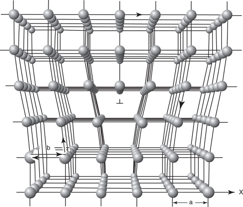
Edge Dislocation
Edge Dislocation: a partial plane of atoms terminated within the crystal structure.
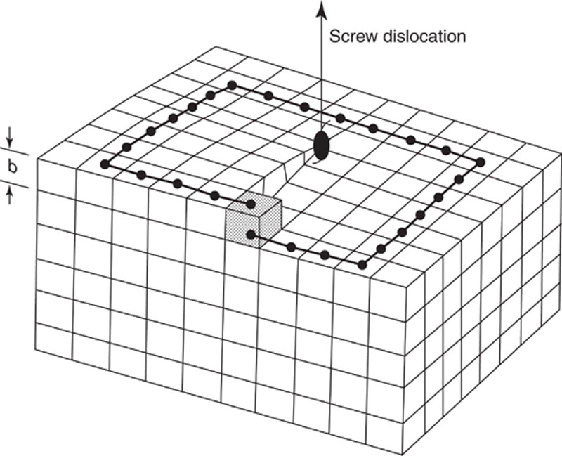
Screw Dislocation
Screw dislocation: produces a line of discontinuity in the crystal structure.
Under an applied load, these types of dislocations can form and multiply leading eventually to the fracture of the ceramic material.
The criteria for plastic deformation are the same as for metals, as follows:
• The presence of dislocations;
• The mechanism of generation of new dislocations under an applied load; and
• A path along which the dislocations can move.
Ceramics are known as very brittle materials. The phenomena of plastic deformation due to the dislocation activity are limited to very high temperatures especially for polycrystalline ceramics. At room temperatures, the random orientation of the grains severely inhibits dislocation motion (which terminates at the grain boundaries). The two mechanisms for plastic deformation are slip and twinning.
2.3. Slip mechanism
Usually slip in ceramic materials occurs on two different slip systems. In most cubic metals, the crystallographically equivalent slip systems are sufficiently numerous to permit complete flexibility. This means that glide of dislocations on slip planes can produce all the strain components and thus produce any change of shape. In ceramics, a minimum of five independent systems is needed to permit an arbitrary change of shape.
Figure 2.2Simple schematic illustrating an edge dislocation and showing that the displacement b (Burgers vector) is equal to one unit cell edge [1]
Figure 2.3Simple schematic illustrating a screw dislocation [1]
In ceramics with ionic bonding, the slip systems depend not only on the crystal structure but also on the ionic positions in the dislocation core. Ceramic materials do not exhibit dislocation mobility at room temperatures. But at high temperatures, limited plasticity is possible, and this may have several origins including dislocation motions, grain boundary sliding, or softening of minor faces. Kronberg (1957) has discussed dislocation motion for alumina in detail. The unit cell for the alumina lattice is made up of six layers of ions parallel to the basal planes that are comprised alternately of aluminum and oxygen ions. All sites are filled on the oxygen planes; in the aluminum planes only two thirds of the sites are occupied. The unoccupied sites (or holes) are arranged regularly but differently on each of the three aluminum planes in the unit cell.
Figure 2.4 shows two of the adjacent basal planes, a completely filled oxygen plane, and partially filled aluminum ions laying in the interstices between the oxygen ions. Deformation of single alumina crystals, at temperatures of 1300 °C or higher, shows that slip can occur on the {0001} basal plane. This is the closest packed plane of alumina, and this represents the expected slip plane. The detected slip direction is <1120>, and it is at 30° to the close-packed direction of the oxygen ions (see Figure 2.4). These geometrical patterns of both aluminum atoms and holes must be restored after shear. Reference to the holes in Figure 2.4 shows that for the <1010> direction, the repeat distance for holes is 3–√ times greater than that in the <1120> direction.
Figure 2.4Oxygen ions (large open circles), aluminum ions (small solid circles), and unoccupied octahedral interstitial sites = holes (small open circles) [11]
Grooves and Kelly (1963) developed a procedure for determining the number of independent slip systems.
Slip occurs most easily on the basal slip system when the temperature of operation is the lowest and the tensile flow stress the smallest of the three possible slip systems. To activate slip on the second and third (prismatic and pyramidal) slip system, the temperature must rise significantly. The basal slip system can be activated most easily, followed by the prismatic and pyramidal ones. For instance, at 1500 °C the stresses needed to activate the prismatic and pyramidal slip systems exceed the stress to activate the basal slip system by a factor of 8 and 16 respectively. Thus, it can be concluded that alumina oxide is a ceramic material characterized by a strong deformation anisotropy. To achieve manoscopic deformation of polycrystalline body by slip, five independent slip systems must operate.
2.4. Twinning mechanism
Twinning is an important mode of plastic deformation, and it has been observed both in single crystal and polycrystalline ceramics. As compared to plastic deformation by dislocation glide, twinning occurs at low temperatures and high strain rates. The experiments on polycrystalline alumina between room temperature and about 500 °C have shown twinning to be the predominant mechanism [2].
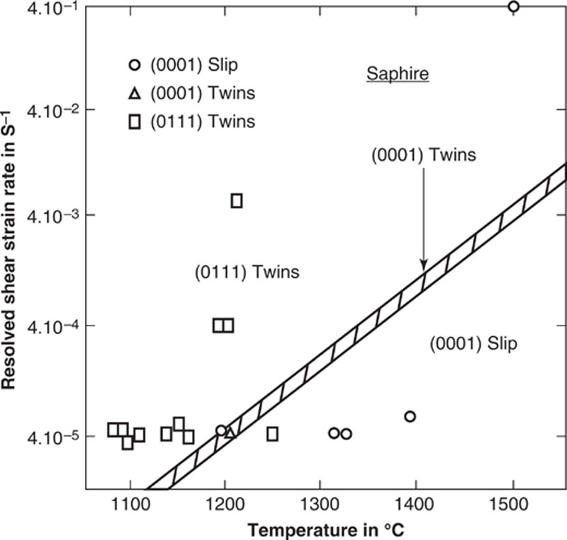
Figure 2.5 illustrates a strain-rate temperature map with three important deformation modes:
• At elevated temperatures and small strain rates (0001) slip prevails;
• At low temperatures and high strain rates, rhombohedral twinning predominates; and
• For a very narrow band of experimental parameters there is a range of (0001) twinning.
Figure 2.5Occurrence of twinning and slip as a function of strain rate and temperature [2]
2.5. Fracture of ceramic materials
It is very important to understand the strength of real polycrystalline ceramics. For this, it is necessary to emphasize the behavior of microcrack under stress. A lot of scientists have studied the linear elastic fracture mechanism (LEFM); this refers to a crack in a continuous body without taking into consideration what happens on an atomic scale. Among them are Kelly and MacMillan (1986), B. Lawn (1993), Hasselman, Munz, Sakai and Sherchenko (1992).
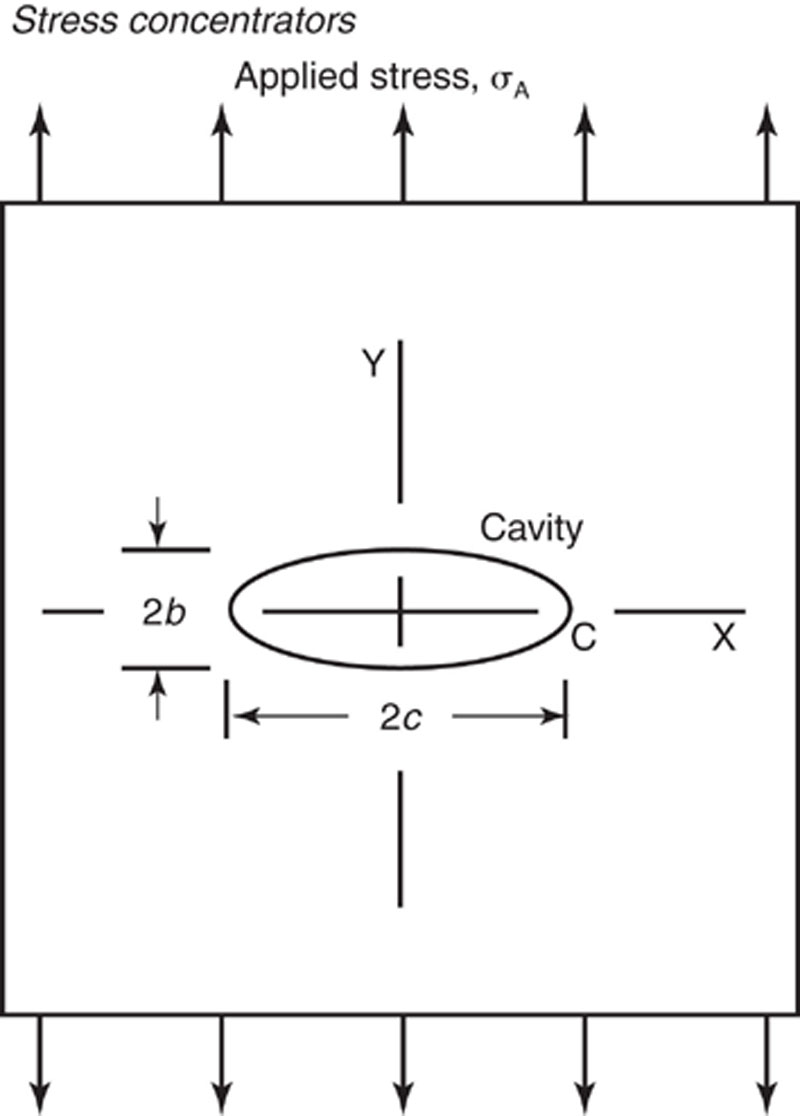
Figure 2.6Plate containing elliptical cavity, semi-axes b, c, subjected to uniform applied tension σ. C denotes notch-tip [3]
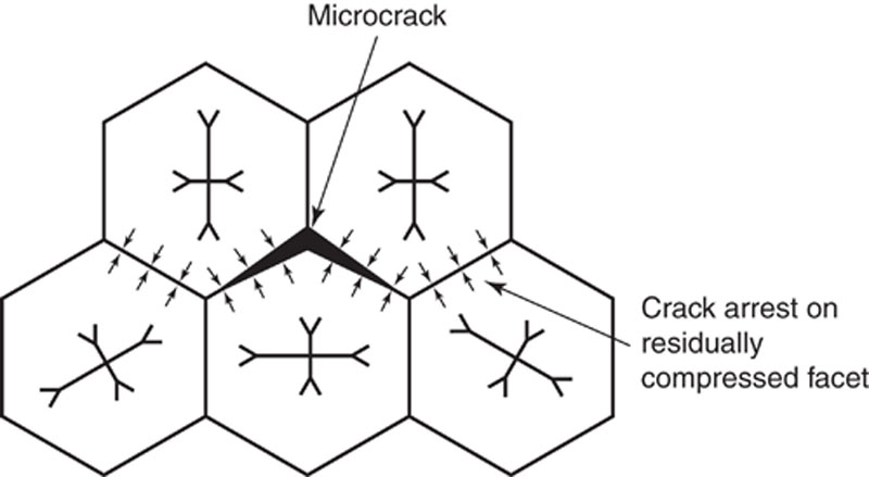
Figure 2.7The location of microcracks with respect to the residual stress on the grain facets [1]
Inglish (1993) says that, considering a sample under a tensile stress σ, if an elliptical flaw is introduced, the tensile stress will change especially near the end of the flaw.
The flaw has the length 2c in the X direction and 2b in the Y direction. The equation of the ellipse is:
x2c2+y2b2=1
(2.1)
and ρ - the radius of the curvature is:
ρ=b2c
(2.2)
The stress distribution around the flaw is very complex:
σyy=σ(1+2cb)=σ[1+2(cp)1/2]
(2.3)
In this equation, there are two characteristics of the elliptical crack: the total length of the crack and the radius of the curvature at the end of the crack perpendicular to the initial stress.
Griffith (1920) presents a theory of brittle fracture based on energy considerations. This theory is still considered the basis of fracture mechanics. He based his treatment on the idea that the brittle body contains small flaws that act as stress concentrators when an external tensile stress is applied. Stresses cannot relax by local plasticity, and the local stress in the vicinity of the most severe flaw may reach the theoretical strength, thus causing the failure of the body.
The Griffith equation of stress is:
S=1y(2Y1Ec)12
(2.4)
where: S is the strength, γ1 is the fracture energy per unit area necessary to initiate failure, E is Young’s modulus, c is the flaw size, and y is a dimension-less constant that depends on the flow size: sample size ratio.
The above equation shows that the strength of ceramics is mainly controlled by two variables: fracture energy and flaw size ratio.
Before discussing the two variables, we present two types of flaw: extrinsic flaws and intrinsic flaws. Extrinsic flaws are defects generated by a particular process of fabrication. The presence of this type of flaw doesn’t depend on the type of ceramic material. Intrinsic flaws are originated at pores, large grains, or second phase particles. Also, they may be generated due to the anisotropy of elasticity or thermal expansion.
Fracture Energy
If a material fractures, energy is required to create the new surface. In polycrystalline ceramics the fracture mode can be transgranular or intergranular, and it is a complicated process compared with the cleavage of a single-crystal or the separation of a bi-crystal. The experimental values of the fracture energy of polycrystals are bigger than the experimental values of the single crystal ysc by a factor of 3-10. According to some scientists (Rice and Davidge), this happened because the true fracture surface of a polycrystal is bigger than the projected surface used for calculating the fracture energy per unit area. They also say that the tortuosity of the fracture surface determines a lot of microscopic deviation of the local crack front from the path of the microcrack. These processes depend on the microstructure: pores, grain size, and the presence of second phases.
When porosity increases, the fracture energy decreases because an increase in porosity makes the cross-sectional area to be fractured smaller.
Y1=Y0exp(−bP)
(2.5)
where: γ0 is the fracture energy per unit area (necessary to initiate failure), b is an empirical constant, and P is the volume fraction of pores.
The influence of the grain size on fracture energy is contradictory depending on the testing method and on the type of specimen used to determine γ. Some authors showed that when the grain size is smaller than 10 μm the fracture energy increases with decreasing the grain size. The grain size dependence on the fracture energy may be due to the microscopic details of crack propagation. For example, in a NB test (notched bend specimen) fracture starts from a single flaw, the dimensions of which are small compared to the specimen dimensions.
Fracture energy increases when microcracking occurs. In ceramic materials, the microcracking can be due to high thermal expansion anisotropy (TEA) or to porosity. The thermal expansion anisotropy provokes stresses across the grain boundaries that become bigger when the grain size is bigger. The dependence of fracture energy on temperature can be seen in Figure 2.8. The fracture energy decreases when temperature increases above 1000 °C.
Figure 2.8Temperature dependence of fracture toughness. Curves (1) to (5): polycrystalline alumina with different grain sizes. Curve (6): single-crystal alumina [2]
Types of Flaws
The flaw size c is an important variable that controls the strength of ceramic materials. Flaws are considered to be pre-existing or stress-induced. The first category has two types of flaws: extrinsic flaws (due to external conditions, like machining and sintering), and intrinsic flaws (which depend on material properties and microstructure).
One type of extrinsic flaw is the stepped flaw. They form by the linking up of the flaws in two or more different planes parallel to the fracture surface. When the ceramic material has a small grain size (c > G, which means the flaw size is bigger than the grain size) the flaw depends only on the machining conditions. In this case, the strength of material is independent of the microstructure.
The residual pores determine another type of extrinsic flaw after sintering. Rice observed that the uniform porosity consisting of many small pores is less dangerous than a small number of large pores. When c G (the flaw size equals the grain size) the strength does not depend anymore on matching processes because the size of the largest grains determines the critical flaw size.
Intrinsic stress-induced flaws may be divided into two groups: those generated by dislocation interaction and those generated by mechanical twinning. Some authors showed that the flaws are generated by dislocation interaction. Other authors showed that the flaws generated by dislocation appear because of the formation of Griffith cracks. Fracture of ceramics can also be determined by mechanical twining in both basal and rhombohedral planes. For example, in polycrystalline aluminum oxide, mechanical twins (twin bands) were detected in many samples. When these twin bands intersect grain boundaries, microcracks can occur and failure appears to be caused by the coalescence of such microcracks.
Dislocation-nucleated flaws in single crystal aluminum oxide Twin-nucleated flaws in single-crystal aluminum oxide Twin nucleated flaws in polycrystalline aluminum oxide
2.6. Indentation in ceramic materials
Many authors (Lawn, Marshall, Evans, and Lankford) described another kind of fracture named indentation. Indentation is very important because it enables us to quantify the brittleness of ceramic materials.
Indentation refers to the contact of a hard indenter on a sample surface, the response of the material, and the crack formation and propagation. In describing indentation fracture, we must consider the contact stress field within which the cracks evolve. This field is very dependent on the indenter shape and material properties (hardness, toughness, and elastic modulus).
Lawn and Marshall demonstrated that hardness H (which represents resistance to deformation) and toughness Kc (which represents resistance to fracture) are very important characteristics to describe the brittleness of ceramic materials. In fact, they proposed that the ratio H/Kc be an index of brittleness.
They studied the evolution of the deformation/fracture pattern for Vickers pyramid indentation, and they also obtained a universal deformation/fracture diagram. Figure 2.9 shows two distinct stages during indentation: initiation and propagation. The initiation cracks begin as full pennies at the boundary between the deformation zone and the surrounding elastic matrix (Figure 2.9a) where the tensile stress is maximum. At a critical load, the subsurface cracks become unstable and expand toward the indented surface. Figure 2.9b shows that finally the stable halfpenny configuration is attained. The equation for the deformation zone is:
Pa2=α0H
(2.6)
where P is the load, a is a characteristic dimension of the impression, α0 is an indenter constant, and H is the hardness.
Figure 2.9Idealized deformation/fracture pattern for Vickers pyramid indentation: showing (a) initiation and (b) propagation stages of median crack development [7]
For the propagation stage, the median cracks develop under center loading conditions and satisfy the equation:
Pc3/2=β0Kc
(2.7)
where β0 is an indenter constant, Kc is the toughness, and c is a characteristic crack dimension.
The c(P) function for initiation stage is more complex:
P*=λ0Kc(Kc/H)3
(2.8)
C*=µ0(Kc/H)2
(2.9)
where λ0 and μ0 are geometrical constants.
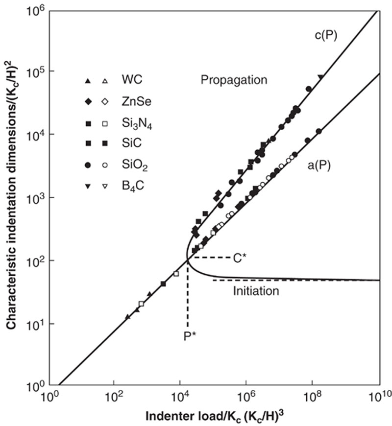
Figure 2.10 presents three distinct regions of mechanical behavior:
(a)P*>P (small-scale events): the contact is insufficient to develop crack nuclei. This means that the damage is totally deformation controlled (usually metals are in this situation).
(b)P*<<P (large-scale vents): median cracks are well developed, c>>a and, therefore, the damage is fracture controlled (typical covalent solids are in this situation).
(c)P*≍P (intermediate-scale events): this region represents the threshold where fracture and deformation are comparable.
Figure 2.10Universal deformation/fracture diagram. Deformation curve is (P) and fracture curve is c(P)[7]
When the size of crack nuclei (a) becomes comparable with (c), the mechanics response is changed from hardness-controlled to toughness-controlled. So, the ratio Kc/K determines the problem of ductility, and the ratio H/Kc becomes an index of brittleness.
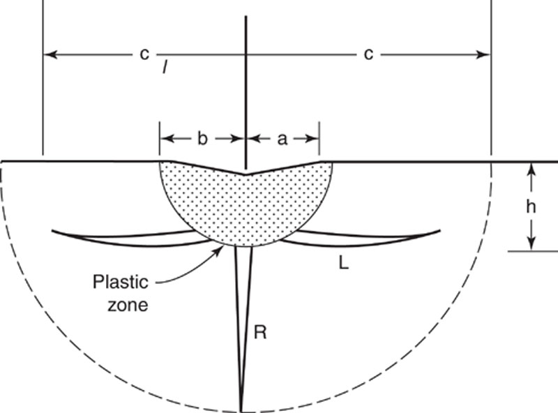
S. Malkin and T.W. Hwang (1996) showed that the indentation fracture mechanics refer to deformation and fracture under a normal contact with a Vickers pyramidal indenter. They observed under the indenter a zone of plastic deformation and two types of cracks that emanate from this zone: median/radial and lateral cracks. Lateral cracks determine the material removal and median/radial cracks determine strength diminution (Figure 2.11).
Figure 2.11Plastic zone, median/radial (R), and lateral cracks (L) for Vickers indentation [8]
The authors studied this problem for a normal load (static indenter) and also for a tangential load (moving indenter). In the first case, both median and lateral crack extension occurred not only during loading but also during unloading.
The median crack propagation is divided into two parts: an elastic component (reversible) and a residual component (irreversible). The elastic component initiates the median crack and causes it to extend during loading. The residual component provides continued crack extension, as the indenter is withdrawn. In the second case (moving indenter), there is not only a normal load but also a tangential load in the direction of motion. The tangential force will increase the tensile stress normal to the direction of motion, which means that the median crack propagation will be higher in the plane of motion (for example, test specimens showed more strength degradation when they were ground transversely than longitudinally).
Lateral cracks appear during unloading near the bottom of the elastic zone, and they will develop laterally on a plane almost parallel to the specimen surface. If these kinds of cracks extend toward the specimen surface, this means that material is removed by fracture (chipping). The crushed zone boundary beneath the moving indenter occurs by fractures originating at preexisting flaws where the elastic strain energy density exceeds a critical value.
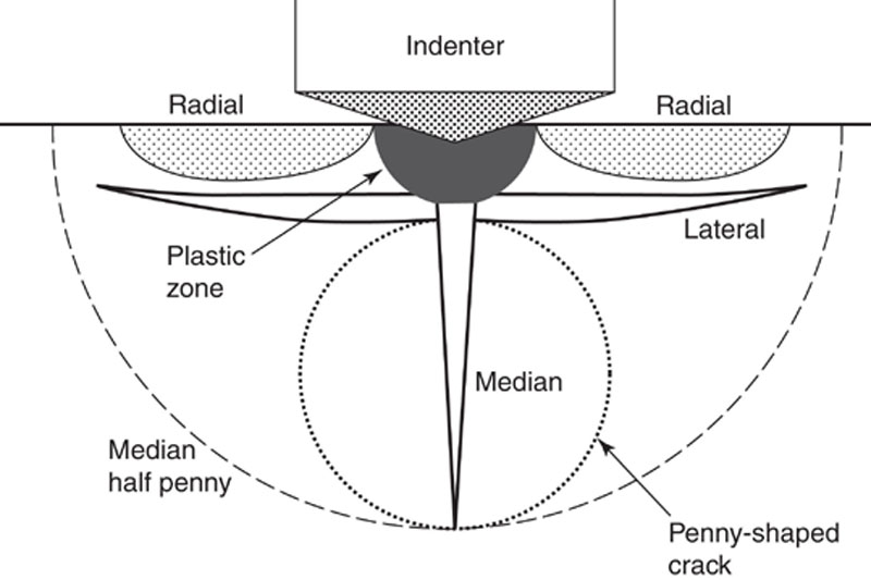
Hyo-Sok Ahn, Lanhua Wei, and Said Jahanmir (1995) [9] illustrated the subsurface damage in ceramics using an ultrasonic technique (normal-incident compression waves) and a thermal wave measurement technique. They used samples from silicon nitride and soda lime glass; the surface and subsurface cracks were introduced by Vickers indentation. The subsurface lateral cracks were detected by ultrasonic technique while the lateral cracks and the median/radial cracks were detected using the thermal wave measurement techniques (Figure 2.12).
Figure 2.12Schematic diagram of cracks generated by indentation of brittle materials with a sharp indenter [9]
For the experiment, they used normal loading by sharp indenters (Vickers and Knoop diamond pyramidal indenters), and they obtained three types of cracks (radial, median, and lateral cracks) under and around the indenter. Figure 2.12 shows that radial cracks begin from the edge of the contact impression in a direction perpendicular to the specimen surface. Median cracks are situated under a plastic deformation zone (also perpendicular to the surface with a circular geometry in the crack plane; they are named penny-shaped median cracks). These cracks can extend toward the surface and join with the radial cracks resulting in halfpenny cracks. The lateral cracks appear during unloading below the surface, and they extend parallel to the specimen surface.
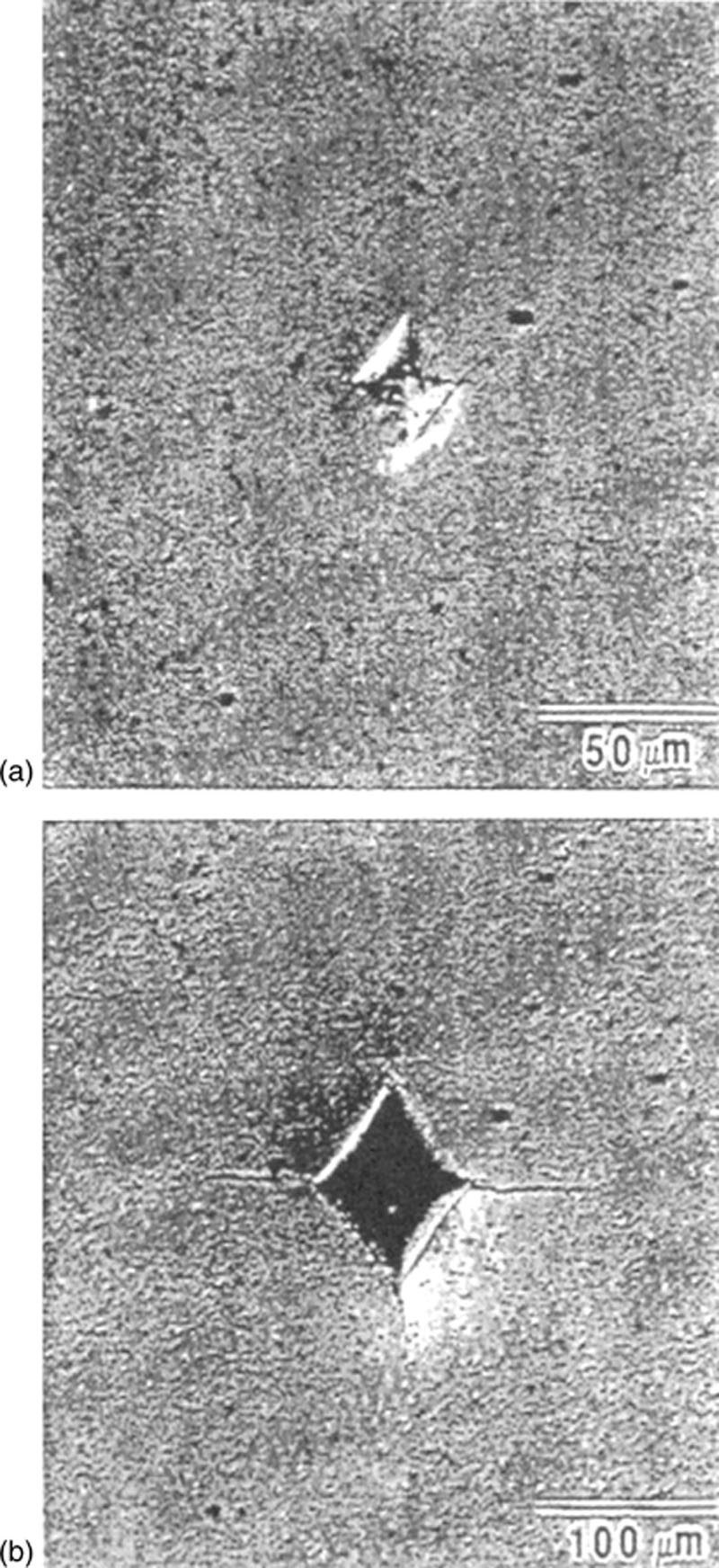
Figure 2.13 shows the optical micrographs of the Vickers indent for the two different loads (7.84 N and 98.0 N) for silicon nitride specimen. The lower load produced a Vickers impression without visible median/radial cracks, and the larger load produced this type of crack at the indent corner.
Figure 2.13Optical micrograph indents in silicon nitride [9]:
(a) 7.84 N load
(b) 98.0 N load
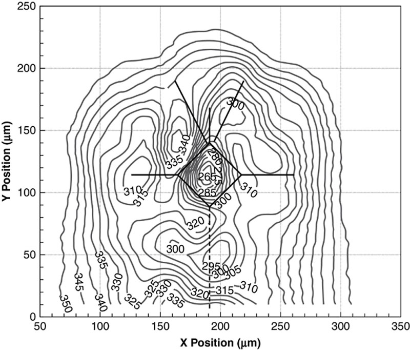
Figure 2.14Ultrasonic echo-amplitude contour plot of the upper indent, using a 50 MHz transducer [10]
The thermal wave measurement technique is very sensitive and can be used to detect surface and near-surface microcracks because microcracks in a material change the local heat flux.
The results of the ultrasonic measurements showed a close correlation between the location of the median/radial cracks and the distortion of the contours.
To conclude, the authors demonstrated that the ultrasonic technique is able to detect subsurface lateral cracks while the thermal wave measurement technique is used to determine both median/radial and lateral cracks in ceramic materials. These types of cracks can be separately identified when using two different deflection components of the probe beam in the thermal wave measurement technique.
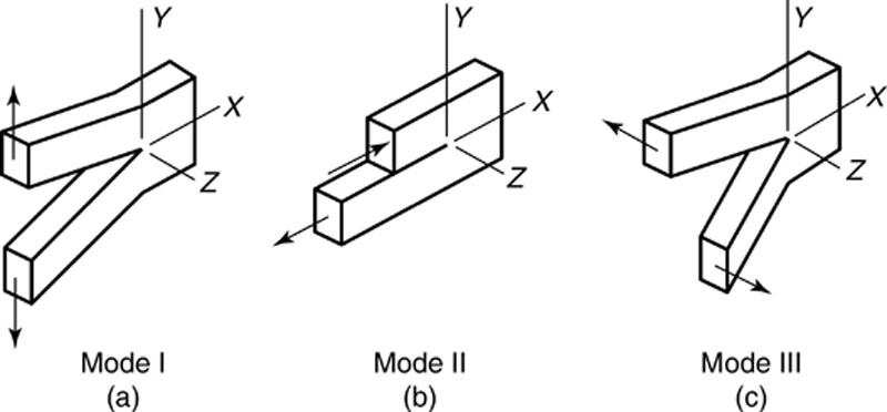
Modes of Crack Tip Deformation
Usually, the load plane is symmetrical with respect to the crack plane. This situation is named “opening mode” (mode 1).
Figure 2.15 illustrates three possibilities of deformation:
• opening mode (mode I): has symmetry on the (x, y) and (x, z) planes;
• sliding or shear mode (mode II): has anti-symmetry on the (x, z) plane and symmetry on the (x, y) plane; and
• tearing mode (mode III): has anti-symmetry on the (x, y) and (x, z) planes.

 ): measured in inches (or centimeters) of deformation per inches (or centimeters) of the initial length or in percent.
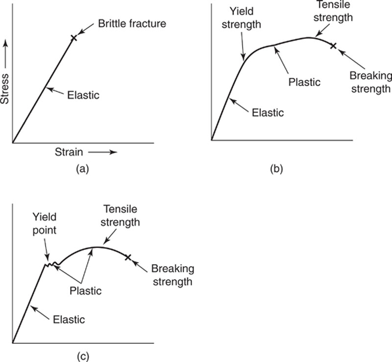
 times greater than that in the <1120> direction.
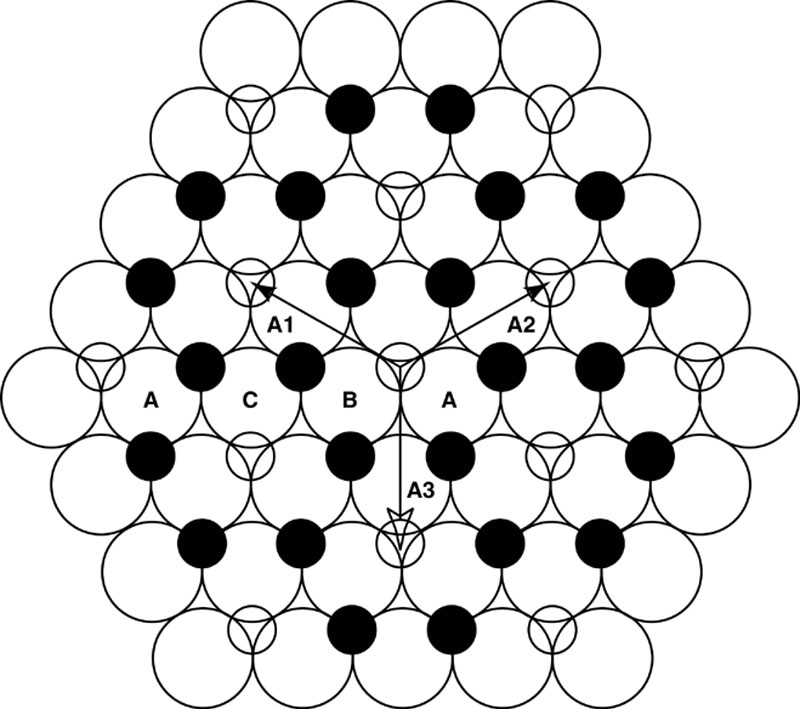
 (2.1)
(2.1) (2.2)
(2.2) (2.3)
(2.3) (2.4)
(2.4)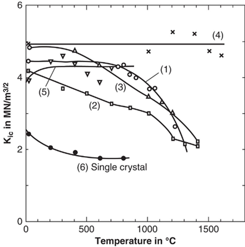
 G (the flaw size equals the grain size) the strength does not depend anymore on matching processes because the size of the largest grains determines the critical flaw size.
 (2.6)
(2.6)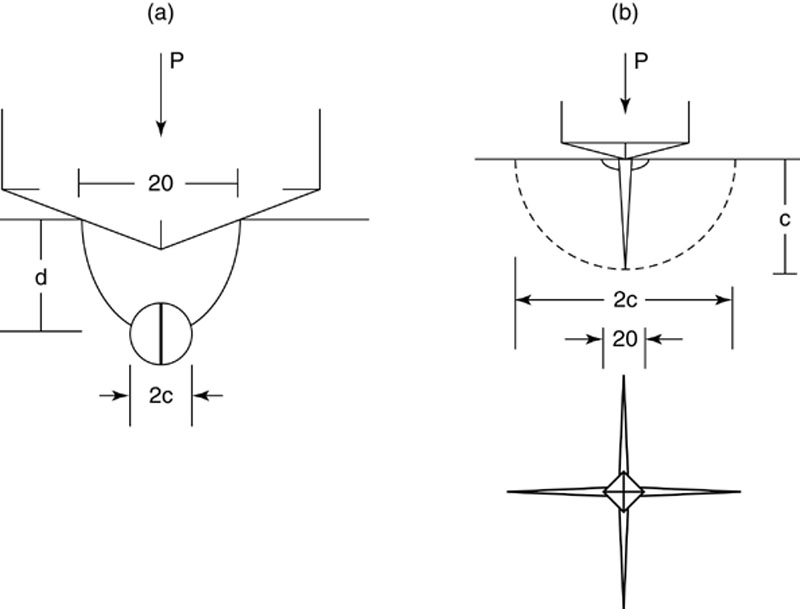
 (2.7)
(2.7) (intermediate-scale events): this region represents the threshold where fracture and deformation are comparable.