Michael Weismiller** * Institute of Education and Research for Engineering, University of Miyazaki, Miyazaki, Japan † Chubu University, Kasugai-shi, Japan § Institute of Machine Tools and Factory Management, Technical University Berlin, Chair of Machine Tools and Manufacturing Technology, Berlin, Germany ** VP for Global R&D, Master Chemical Co., Perrysburg, USA
Abstract
A material wherein abrasive grains are bonded together by a bonding material is known as a whetstone. The whetstone comprises abrasive grains, a bonding material, and pores. The abrasive grains play the role of a cutting edge, the bonding material fixes and supports the grains, and the pores act as a chip pocket to help discharge of cutting chips. In whetstones where the bonding material is a resinoid bond or metal bond, there are not normally any pores.
The process whereby a grinding wheel which is a circular whetstone is rotated, and the surface of a workpiece is gradually ground down by the abrasive grains on the grinding wheel, is referred to as grinding. Grinding can produce very high shape accuracy and dimensional precision even with hard workpieces like ceramics, or permit a surface with a satisfactory roughness to be obtained, and is therefore an extremely important processing technique.
Keywords
Theory of Grinding
Characteristics
Grinding tools
Grinding Wheel Design
Bonds materials
Cores
Wheel Description
Diamond Grit Type
Cooling Lubricants
4.1. Fundamentals of grinding
Osamu Ohnishi
Introduction
A structure in which abrasive grains are bonded together by a bonding material is known as a whetstone. Figure 4.1 shows the general structure of a whetstone. As can be seen from the diagram, the whetstone comprises abrasive grains, a bonding material, and pores. The abrasive grains play the role of a cutting edge, the bonding material fixes and supports the grains, and the pores act as a chip pocket to help discharge of cutting chips. Whetstones in which the bonding material is a resinoid bond or metal bond normally do not have any pores.
Figure 4.1General structure of whetstone
When a grinding wheel (or circular whetstone) is rotated and the surface of a workpiece is gradually ground down by the abrasive grains of the grinding wheel, the process is referred to as grinding. Grinding can produce high shape accuracy and dimensional precision even with hard workpieces such as ceramics. It can also permit a surface with a satisfactory roughness to be obtained and is therefore an extremely important processing technique.
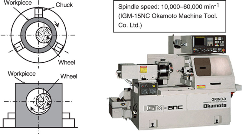
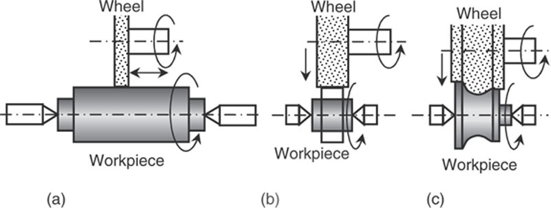
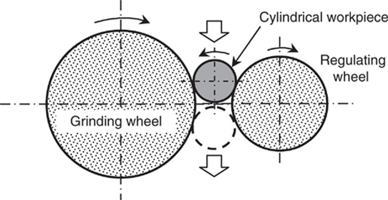
As shown in Figure 4.2, various types of grinding can be performed, such as cylindrical grinding of the outer surface of a cylindrical workpiece, internal grinding of the inner surface of a cylinder, surface grinding of a flat face, and centerless grinding of workpiece without using a chuck to hold the workpiece.
When grinding is performed, as shown in Figure 4.3, grinding performance will deteriorate if the surface of the grinding wheel becomes clogged with chips (known as loading), the tips of the abrasive grains wear down (known as dulling), or excessive numbers of abrasive grains fall off the surface of the grinding wheel (known as shedding) [1]. When cutting performance has declined due to loading or dulling, the dressing is performed to remove chips from the clogged surface or worn abrasive grains and to recover the cutting performance of the abrasive grains. Also, when the grinding wheel is mounted on a spindle, truing is performed by adjusting the shape of the grinding wheel to eliminate run out of the grinding wheel surface. Dressing and truing are extremely important in order to perform grinding work with high precision. If the grinding conditions and grinding wheel are chosen appropriately, a self-dressing process will occurs [2].
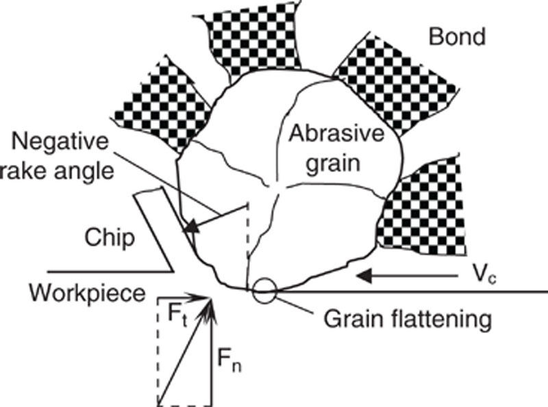
Cutting and grinding are mechanical processes that remove unnecessary parts of a material by sinking the cutting edge of a tool into a workpiece. In cutting, machining is performed by a cutting tool that has a cutting edge of the desired shape, whereas in grinding, machining is performed by large numbers of abrasive grains scattered on the outer surface of the grinding wheel. These particles do not have orderly shapes, and as shown in Figure 4.4, the rake angle of the grain cutting edge has a large negative value. In addition, although the abrasive grains are fixed by a bonding material, they wear down, chip, and fall off during machining, so machining conditions are not constant. At the same time, grinding can make many fine cuts that can be made at high speed, but the work surface is easily damaged by heat as a result. To better understand grinding, we shall discuss some essential basic theory in the same way as many other works [3,4].
Figure 4.4Conditions of cutting edge. (a) Cutting, (b) grinding
Figure 4.5
shows a model diagram of grinding. Here, let the circumferential speed of the grinding wheel be V, the workpiece speed be v, the depth of cut of the abrasive grains be a, and the diameter of the grinding wheel be D. Let us consider abrasive grains X1, X2 on the grinding wheel. Assume that after particle X1 has cut along an arc ABC, particle X2 cuts along an arc DEF. In a strict sense, the path of the abrasive grains is a trochoid curve (see Figure 4.6, but because V v, it may be considered as an arc. Assume the center of the arc ABC is O1 and the center of the arc DEF is O2. At this time, let g (= length of line CG) be the maximum grain depth of cut. Also, let l (= length of arc DEF) be the grain cutting length. The arc DE is fairly short, so the grain cutting length l may be calculated as arc EF.
The grinding force acting on one abrasive grain depends on the mean area of chip section. Consequently, when the mean area of chip section increases, the grinding force also increases, which leads to problems. When problems arise, we should therefore consider how to adjust the values of the parameters on the right-hand side of equation (4.8).
Characteristics of Ceramic Grinding
Among ceramics, fine or advanced ceramics that have superior engineering characteristics are used for various types of instruments and parts. Fine ceramics are extremely hard and difficult to machine. In grinding fine ceramics, the material is destroyed because it is brittle; that is, it is brittle mode grinding, so it is important to perform machining without giving rise to cracks in the material, and to machine with high performance.
We shall consider ductile mode grinding for removing even brittle material by plastic deformation without cracks [5,6]. To perform ductile mode grinding, the maximum grain depth of cut g should always be less than the critical depth of the cut.
Here, let us consider the maximum grain depth of cut with reference to Figure 4.5. The number of abrasive grains (Ns) on the same circumference is:
Ns=πD/w
(4.9)
On the other hand, the workpiece speed (v) may be expressed as follows in terms of the feed (f) per abrasive grain, and the rotational speed of grinding (n):
v=Nsfn
(4.10)
The circumferential speed (V) of the grinding wheel is:
The line O1O2 is equal to the value of f. If the angle EO2C is β.
sinβ=√(D/2)2−(D/2−a)2−fD/2−g
(4.13)
The following is also true:
sinβ=√(D/2−g)2−(D/2−a)2D/2−g
(4.14)
Normally, V v, D g, D a, so the maximum grain depth of cut g is given by the following equation:
g≍2wvV√aD
(4.15)
When we wish to make the value of g approach the critical value, we should consider how to adjust the parameters on the right-hand side of equation (4.15).
In rough grinding, because the presence of cracks arising in the workpiece is not a great concern, brittle mode grinding is performed at a high grinding speed. On the other hand, the need to avoid cracks in the workpiece and to reduce the surface roughness in finishing grinding indicates that ductile mode grinding may be performed.
4.2. Grinding tools
Hirofumi Suzuki
Introduction
Cutting is generally way of machining of metal where the tool parameter, such as rake angle, relief angle, and wedge angle, is idealized. On the other hand, grinding is practically the best machining method of ceramic materials in the fired state. Their great hardness and high wear resistance necessitate production systems that work with loose or bonded abrasives. The physical properties of diamond make it particularly suitable as an abrasive for these applications. On the wheel surface, many cutting abrasives are possible, like a milling as shown in Figure 4.7. Assuming that the practical issues of technological application are resolved, the economics of operation are the decisive factor. The key factors in grinding with diamond wheels are the selection of the machine and cooling conditions, the optimization of the diamond grinding wheel, and the associated dressing and trueing strategy.
Figure 4.7Comparison between cutting and grinding. (a) Cutting (b) Grinding
Diamond wheels are different from conventional wheels in several respects. Basically, the tool system may be broken down into three subsystems: the abrasive system, the bond system, and the cope system (Figure 4.8. The diamond wheels themselves feature high macrogeometrical accuracy as delivered.
Figure 4.8Expanded market horizon
Grinding behavior in application is largely determined by the microgeometrical characteristics of the chip space of the grinding wheel. The initial state of the grinding layer determines the initial wheel-cutting behavior, the initial wear, and thus also the nonsteady-state break-in phase. The grinding wheel topography reflects wheel composition and any dressing processes that have taken place.
In the past, the application of diamond grinding wheels was mainly determined by technical and economic features. Today, the selection of diamond wheels is largely determined by other, additional criteria (Figure 4.8), including aspects such as recycling capability of the raw materials and cores, industrial health and safety, the raw materials used and waste disposal, and aspects of energy input per volume unit of the material to be machined. Ceramics machining, in particular, is characterized by high-performance grinding processes such as creep-feed grinding and high-speed grinding, which open up technological and economic perspectives. It also means new requirements for grinding wheel design and strength and mounting systems.
Grinding Wheel Design
Grinding wheel consists of (a) abrasive, (b) bond, and (c) pore as shown in Figure 4.7(b). In this section, these three factors are described.
Abrasive Materials
Abrasives are the tool for cutting ceramics. An important criterion for the specification of an abrasive is the hardness of the workpiece material. A hardness comparison between ceramic and metallic materials shows that diamond, in particular, is suitable for hard machining ceramics. The diamonds used for this purpose are mainly synthetic diamonds, which are manufactured by lattice conversion from the soft hexagonal layer-lattice structure of graphite. This process gives a considerable increase in density and an extreme increase in hardness (Figure 4.9).
Figure 4.9The density and hardness of natural diamond, synthetic diamond, and CBN
Diamonds differ in their external morphology. Basically, crystals are built up from initial cubic and octahedral shapes and their combinations. Grinding applications use either grown crystals or crushed grits. These basic shapes may be influenced by the synthesis parameters. The synthesis process permits control of diamond characteristics, generating either blocky grit shapes with high-impact strength, or friable grits with low impact strength. Diamonds are also classified by grit size and grit size distribution. Micron grits, in particular, may be specified by asymmetrical grit size distributions; that is, the size range is limited in one direction.
Thermal transition behaviors among diamond, bond, and cohesion in specific bond types may be improved by giving the diamonds metal coatings, which are generally copper alloys or nickel phosphorus alloys. Thermal conductivity is an important physical quantity (Figure 4.10) and highly dependent on the purity of diamonds. Thus, the thermal conductivity of high-purity diamonds is about 2,000 W/mK, which is far above the thermal conductivity of all other materials. Even synthetic diamonds used for grinding applications have higher thermal conductivity than silver or copper.
Figure 4.10Properties of diamond and CBN
The metal coatings used basically have two functions to fulfill. First, their external structure can be varied. They can have rough, jagged, or even spiky surface structure, which provides good mechanical anchoring of the grits in the resin bond. Second, the nickel-phosphorus layer has considerably lower thermal conductivity than diamond, and thus acts as a thermal retarder as long as thermal breakdown of the resin bond is avoided. The wide variety of capabilities shows that the grit system can be used to control the desired working result within a wide range.
Diamond is the hardest known cutting material, but this hardness is dependent on temperature. It decreases considerably above 600–700°C in an oxidizing atmosphere (Figure 4.11). At higher temperatures, the diamond lattice is converted to a hexagonal layer lattice. It is important to be aware of these factors in order to prevent thermal overloading of the diamond by providing adequate cooling/lubrication and by proper specification of the other process parameters. Another danger arises when carbon atoms from a partly graphitized area diffuse into the workpiece and cause chemical wear in the presence of a chemical affinity with the workpiece when the activation energy is exceeded.
Figure 4.11Cores
Bonds Materials
Most of the wheel is multilayer wheel. With multilayer diamond grinding wheels, the grits are held in a metal, resin, or vitrified bond. These grinding wheels can be dressed. On the other hand, an electroplated monolayer grinding wheel, or monolayer wheel, is a metal-bonded diamond wheel that cannot be dressed.
• Metal Bonds: Metal bonds mainly use modified copper/tin and cobalt/bronze materials. Iron/copper/tin systems are also used in special applications. Reports from Japan indicate the use of gray cast iron bonds in diamond wheels for ceramics grinding [7,8]. The composition of the bond and the manufacturing parameters basically produce changes in abrasive wear resistance and ductility/brittleness of the bond. The main feature of metal bonds is that they key in the diamond intensively and give high abrasive wear resistance to small detritus that occurs when machining short-chipping materials. In other words, additional sharpening processes are normally necessary when grinding ceramics with metal-bond diamond wheels. Wheel manufacture is done by sintering at high temperature; the diamonds used for metal bonds must have high heat resistance in order to avoid thermal damage from this process.
• Resinoid Bonds: The material used to bond the diamond in the resin matrix is mainly phenolic, and fills may be added to control the bonding characteristics. These fillers may be used to change wear resistance and thermal conductivity or may serve as solid lubricants. Polyamide resins may be used instead of phenolic resins. These polyamides have higher strength, thermal stability, and elasticity. Resin bonds are mainly used with metal-coated diamond grits in order to improve mechanical anchoring in the bond matrix. Wear resistance against abrasion is considerably lower than with metal bonds.
• Vitrified Bonds: Resin bonds and metal bonds are generally manufactured free of pores (as determined by bond formulation and manufacturing conditions), unlike normally fired vitrified bonds, which have a defined pore content. Thus, their structure is basically the same as that of conventional abrasives. However, due to the mechanical/thermal properties of the diamond, these bonds are designed quite differently. Differences are also found in firing temperatures and firing characteristic. Vitrified bonds can be manufactured free of pores by the hot pressing technique.
• Monolayer Wheels: In electroplated monolayer grinding wheels, the layer thickness corresponds approximately to the mean grit size used. Monolayer wheels cannot be dressed, and wheel life ends when the layer no longer provides the required performance. Monolayer vitrified-bond wheels are used to true profiles, particularly for machining ceramics in green state. The service life of the wheels is long, and tool change is not required at short intervals. But it is important to remember that the behavior of monolayer wheels changes during the grinding process. It is not possible to achieve a virtually steady state in the grinding process, because the wheel has only one layer of grit. Steady state is not so important in the machining of ceramics in green state, because the wheel layer components are subjected to only minor abrasive attack by the chips removed from the workpiece. Longer wheel life is due to low wear gradient over grinding time.
The available chip space is determined by grit protrusion over the bond and also by the usable grit volume available for the chip-removal process. The trade-off here is between sufficient retention strength of the grit in the bond (which increases with increasing layer thickness) and maximum chip space (achieved by small layer thickness). Bond material is usually an electrolytically deposited nickel layer, with a thickness of about 50% of mean grit diameter.
Two other bonding systems are possible for monolayers. The first alternative is chemically deposited nickel-phosphorus alloys. Following further thermal treatment, these alloys have considerably higher hardness than electrolytically deposited nickel layers. They also give a more uniform layer thickness, especially with large profile depths. The drawbacks of this process are that more extensive production facilities and considerably higher deposit temperatures are required. In addition, a greater crack sensitivity results from the greater brittleness of the deposited bond layer. The mean layer thickness is likewise 50% of the mean grit diameter.
The second alternative for metal-core diamond wheels is high-wetting active brazing materials [9,10]. If titanium-containing brazing materials are used, production requires either a vacuum of <10–4 bar, or an argon atmosphere; other complex brazing materials on a Ni-Cr-Bo-Si base also require an inert gas atmosphere. The use of active brazing materials and high-wetting capability makes it possible to achieve mean layer thicknesses of about 20% to 30% of mean grit diameter, making correspondingly larger chip spaces possible. This production technique requires complicated equipment. It also requires steel cores due to the high manufacturing temperatures, and it is not possible to manufacture highly accurate profiles because of thermal expansion. Reproducible production of uniform cutting-layer properties is particularly difficult with profiles, because it is practically impossible to control grit size distribution accurately enough. In addition, the greater chip space has only slight influence on grinding and wear behavior when machining ceramics. All these factors mean that the benefits, which are theoretically possible, are difficult to achieve in practice in ceramics machining. For this reason, these bond systems have not yet achieved wide application.
Cores
Unlike conventional grinding wheels, diamond layer can be combined with a wide range of different core materials, providing a wide parameter field for adapting the diamond wheel to the specific machining operation. This capability is particularly important in the machining of brittle ceramics, permitting optimal adaptation of the wheel to the specific properties of the material, especially with respect to vibration behavior thermal conductivity (Figure 4.11).
For monolayer diamond wheels, an electrically conducting core is necessary. Metallic materials, such as steel and aluminum, are mostly used here. Carbon fiber–reinforced cores with resin matrix may be used in special applications requiring extremely high peripheral speeds [11].
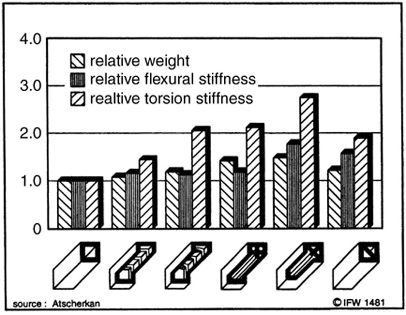
A wide range of different grinding layer/core combinations for multilayer grinding wheels is available. A selection of combinations is shown in Figure 4.12. When machining ceramic materials, it is important to minimize external vibration sources because of the brittle nature of these materials. The grinding wheel system should therefore be optimized to reduce runout error, clamping error, and grinding wheel unbalance. The vibration effect of these possible error sources can be minimized by keeping the weight of the grinding wheel low. Resin composite cores are often used in these applications because they feature low weight, high intrinsic damping, medium strength, and thermal conductivity.
Figure 4.12Grinding layer
Wheel Description
The full description of a grinding wheel must give information on geometry, layer composition, and core (Figure 4.13). The most important wheel shapes are codified in the FEPA standard and have been incorporated in ISO 6168-1979. In Europe, the description of micron powers mostly uses the FEPA standard, which has likewise been taken over in ISO 6106-1980 and in DIN 848. In the United States, the sieve sizes are mainly indicated to U.S. standard ASTM E11.70. Micron powders smaller than D46 (FEPA) or 325/400 mesh (ASTM) are currently not standardized. For micron powders, the classification is no longer done by sieving but by sedimentation.
Figure 4.13Shape of grinding wheel
The grit concentration describes the volumetric diamond content in the layer volume. The baseline value is 4.4 carats per cm3 layer volume, which is generally indicated as C100. The calculation with diamond density shows that C100 gives a percentage by volume of 25%. Thus, C50 means that diamond content is 2.2 carats per cm3.
Tailoring the Wheel to the Material and Process
Grinding Ability
The grinding behavior or grinding ability of the wheel is general terms, referring both to the physically defined parameters and the empirical values from practical operation. They describe the ability of a wheel to grind a given material under defined conditions. It is not possible to quantify this parameter. At most, it can be done with reference to a specific application. For this reason, the grinding ability of a wheel is not given exclusively with the heel parameters but always takes into account the specific cutting properties of the material, the dominant kinematic parameters of the grinding process, and grinding wheel data.
Despite this complexity, it can make sense to distinguish the various families of bonds from one another, as an initial guideline to help select the bond for a given application (Figure 4.14). Bonds with a wide fluctuation in range of properties make particularly severe demands on application preparation and constancy of the grinding process. On the other hand, they make it possible to increase performance by controlled use of outstanding performance features. Performance capability can be optimized by a wheel tailored to the specific application, although a wheel with slightly different properties may be easier to use and may not react so sensitively to process variations.
Figure 4.14Guidelines for bonding selections
Precision Machining, Finishing Machining of Contours
The main feature in wheel specification for finish machining of ceramics is the avoidance of local stress peaks, which may lead to sudden unpredictable brittle features of the component. The most important rule in wheel specification is therefore to avoid or suppress crack growth that might cause a rise in maximum feature stress [12,13]. Even in brittle materials, it is possible to achieve ductile behavior under certain conditions, as shown by extensive and detailed crack tests with single grit wheels and systematic studies of process parameters [13]. These conditions are as follow:
• Low force per individual grit
• Small individual chip thickness, not exceeding a certain material specific value
• Large cutting point radii generate compressive stress fields and promote ductile grinding. However, this only takes effect if there are no simultaneously higher normal forces and considerable heat development to offset the positive effect described earlier.
Therefore, creep-feed grinding and high cutting speeds may be favorable, provided that they are not offset by thermal damage, which may occur directly on the grinding wheel and also directly on the workpiece.
Rough Grinding
The optimization criteria are different in rough grinding in this case than are subsequent operations for removal of further surface layers. The allowances for final machining must be greater than the surface zone subject to damage from rough machining. The following optimization criteria must therefore be included in wheel design:
• Low energy requirement for removal of one material volume unit (This is favored by brittle facture chip formation. The chip thickness must exceed a material-specific thickness.)
• Low increase in force vs. material volume removed
• Low specific wheel wear
Wheel Specification
In keeping the target criteria mentioned earlier, diamond wheels for machining brittle ceramic materials must be specified in two basic stages.
Rough Design
Based on the material to be machined, the emphasis is on the following:
• Part geometry
• Intended dimensional, shape, and positional accuracies
• Surface qualities
The machine parameters, such as dressing and trueing process, are then taken into consideration to specify the following:
• Wheel diameters
• Wheel bond
• Diamond
Fine Design
The fine adjustment phase is to optimize wheel composition based on the thermomechanical properties of the material to be ground, with the following goals:
• Finish grinding: To minimize the surface zone influenced by grinding
• Rough grinding: To achieve an energy-efficient brittle fracture process
The main parameters here are process technology (such as creep-feed grinding, reciprocating grinding, up/down grinding, high-speed grinding) and coolant/lubricant parameters. The goal is to optimize the following:
• Diamond grit type
• Diamond grit size
• Diamond concentration
Wear Mechanisms and Diamond Grit Type
The different forms of wear of the diamond grit depend on wear state (Figure 4.15). Wear on the grinding grit starts mainly where the outer grit regions experience thermal load. If the temperatures are too high, the diamonds may be graphitized in some areas, which causes considerable reduction of wear resistance. By this mechanism, the abrasive grits wear to flat shape as shown in Figure 4.15(b). Flats due to abrasion and thermal effects may also be caused by the use of wear-resistant bonds with high grit retention force (e.g., metal bonds), high-impact-strength diamond types that do not splinter easily, high wheel peripheral speeds, and creep-feed grinding. With friable grit types in particular, even small mechanical overloads may be sufficient to form new, sharp secondary cutting points by partial breakout of diamond fragments (Figure 4.15(d)). With blocky diamonds, a mechanical overload under conditions of sufficient retention in the bond may cause partial grit breakout, but the number of new secondary cutting points generated is smaller, and the cutting points are elongated and not so pointed or sharp-edged (Figure 4.15(e)). Complete grit breakout occurs if the retention force of complete grits or groups of grits is exceeded (Figure 4.15(c)).
Figure 4.15Abrasives wear mechanisms and diamond grit type [15]
The wear forms on the diamond grit cause a direct influence on the individual grit contact forces and total grinding forces, which in turn act as reaction forces on the workpiece. The wear forms on the diamond are determined not only by the process parameters occurring in the cutting zone, but also by retention capability in the bond. So assessment of diamond grit types must also take account of the bond.
The small size of chips and the high abrasive wear resistance of the bonds mean that bond wear plays only a minor role in the grinding of most engineering ceramics. On the other hand, the hardness difference between the material to be ground and the diamonds is relatively small, so the change in cutting edge topography is mainly determined by grit wear. This change in turn causes the grinding wheel surface to be smoothed, and the cutting edges further down are soon engaged in the cutting process, increasing the grinding forces that are reinforced by the reduction in available chip space.
Thus, both the grit type and the bond are vitally important in wheel specification. A calculation model has been developed showing that with friable diamonds, the wear on the diamond cutting edges is, on average, evenly distributed over the material volume. This distribution is demonstrated by only the slight changes in the cutting edge rounding radius and minimal increase in cutting point density. With blocky diamonds, the formation of pronounced wear flats tends to cause a considerable increase in rounding radius versus material volume removed (Figures 4.16 and 4.17). Under otherwise identical conditions, the radii generated on the grits correspond to the average grit diameter.
Figure 4.16Cutting edge rounding ratio of SiSiC and Al2O3
Figure 4.17Cutting edge rounding ratio of SiSiC and Al2O3
Blocky diamond grades with low grinding wheel wear should be considered where rigid machine systems are used, contact length engagement is small, and sufficient coolant/lubricant can be applied. Together with suitable bonds, the conditions then may be such that damage-free workpiece surfaces can be achieved only with blocky, high-impact-strength grit types [13]. Blocky diamonds are likewise preferable to friable types where high material removal rates have to be achieved by high-speed grinding in the energy-efficient brittle fracture range. Metal bonds have only limited suitability for high-speed processes, due to the high normal forces occurring; favorable cutting force characteristics and wheel life between dressings can be achieved with vitrified-bond and resin-bond wheels as shown in Figure 4.18.
Figure 4.18Cutting force characteristics and wheel life
In creep-feed grinding of HPSN with phenolic resin diamond wheels, variation of the diamond grit type under otherwise identical parameters showed that blocky diamond grit types give considerably higher normal forces in the grinding process. The reason is because flats are generated during the grinding process, with simultaneously reduced ability to form new sharp cutting edges by splintering (Figure 4.19). In order to achieve lower mechanical and thermal stress on the ground surface zone, it is preferable to use sharp-edged, friable diamonds to machine HPSN, even though they may cause a slight increase in wheel wear and coarser surface quality. Extremely friable diamond grit types generate the lowest normal forces, but also the highest wheel wear.
Figure 4.19Effects of diamond grit type on wheel wear [15]
Grit Size
Grit size has an influence on the attainable surface quality, the wear behavior, and the grinding forces occurring in the cutting process. Finer grit sizes generate better surface qualities and higher normal forces in reciprocating surface grinding with small in feeds up to ac = 0.1 mm. These conditions may be reversed in creep-feed grinding of HPSN with phenolic bond grinding wheels (Figure 4.20). Here again, larger grit sizes produce higher grinding forces because large grits are retained more firmly in the bond and form larger wear flats. The wear influence on the grinding forces that occur in the cutting process is thus considerably stronger than the decrease in the number of cutting edges due to the increase in the size of the diamond grit. In other words, grinding wheel topography, and thus grinding behavior, is decisively dependent on cutting edge protrusion over the bond. Sharpening and optimal grit protrusion are decisive both for wear and for the grinding forces generated. If the chip space preparation by the sharpening process or other suitable processes is not carried out in the manner appropriate to the material and machining parameters, it is not possible to achieve satisfactory working results even with optimized grinding wheel composition.
Figure 4.20Effects of grit size on surface roughness [15]
The selection of suitable grit size is also influenced by the material to be ground. The lower the hardness of the ceramic material to be machined, and the more the process operates with brittle feature, the less pronounced will be the wear flat on the cutting edge. Therefore, smaller total grinding forces will occur in cases with larger grit sizes, which has been demonstrated in grinding zircon oxide, compared with HPSN and SiC [15].
Grit Concentration
An increase in grit concentration causes an increase in the number of active cutting points. A decrease occurs in the average distance from one cutting edge to another, and the average maximum chip thickness decreases under otherwise identical kinematic contact conditions. The result is a decrease in the individual grit contact forces.
However, these decreases do not mean that a higher grit concentration will always give a better working result. The volumetric grit concentration must be adapted to the machining application.
In reciprocating grinding with small infeed increments, the grit concentration has only minor impact on forces and surface qualities. Closer correlations have been observed in face grinding with large contact surfaces and in surface creep-feed grinding. In creep-feed grinding of various ceramics, the volumetric grit concentration need to be adapted to the workpiece material. In grinding HPSN, a considerable force increase occurs with an increase in grit concentration from C50 to C100 (Figure 4.21). However, this force increase is not true to the same extent for radial wear, which suggests that flat formation on the cutting point is a major factor in force increase. Wheels with high concentration are therefore not advisable for creep-feed grinding of HPSN. With SiSiC, which tends more towards brittle facture, the thermal load on the grinding layer components is lower, with less wear in flat formation. Only a slight increase in total grinding forces occurs as concentration rises. In this example, it also means that higher grit concentration causes lower individual grit engagement forces. Increased concentration thus gives considerably lower wheel wear (Figure 4.21).
Figure 4.21Effects of grit concentration on wheel wear [15]
In summary, materials that exhibit extreme brittle fracture and good thermal conductivity reduce thermal loading of the wheel bond and of the diamond grit. Higher grit concentration may be expected to give benefits if these conditions are met due to the material or to other process parameters.
Dressing Strategy and Bond Specification
The decisive factors for grinding behavior include not only grit type, grit size, and concentration, but also specification of the bond system and conditioning of the grinding layer. The interplay between wear process on the grid and on the bond determines grinding behavior and the working result. Evidence is shown in the example of creep-feed grinding HPSN with various diamond wheels (Figure 4.22). The least sensitive reaction is that of vitrified-bond diamond wheels to different dressing conditions. The vitrified bond has brittle facture behavior, and the bond webs are weakened by the existence of pores in the cross-section. This situation results in low grinding forces during grinding because wear causes the diamond grits to break out of the bond at an early stage without forming large wear flats, resulting in low normal force and high wheel wear. Metal bond wheels in particular react strongly to differences in dressing. Normal forces are significantly reduced by wheel dressing, and also in wheel wear, but not to the same extent. Therefore, even with metal bond wheels, the use of suitable dressing conditions can produce process parameters comparable to those of vitrified bond and resin bond wheels. Knowledge of dressing behavior, the use of suitable dressing units, and the appropriate dressing strategy is necessary.
Figure 4.22Effects of diamond wheel type on surface quality in creep-feed grinding of HPSN [15]
Figure 4.23 shows a summary of the various study results on the influence of wheel composition on process parameters and working results.
Figure 4.23Influence of wheel composition on process parameters [15]
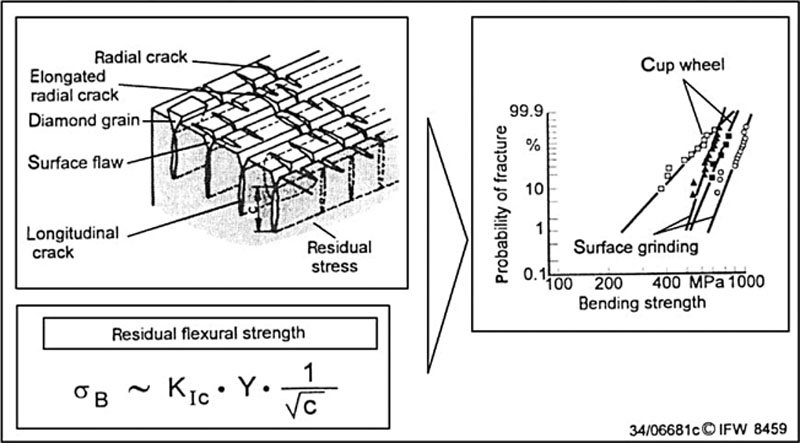
Bending Fracture Strength
The mechanical and thermal load on the surface zone is influenced by wheel composition, including grit type, grit size, concentration, and bond. These factors overlaid by changes in wear condition of the active cutting edges over time and by the number of active cutting edges.
An example of the results obtained in creep-feed grinding of HPSN is shown in Figure 4.24. The use of sharp-edged, friable diamonds in phenolic resin bond with a concentration of C50 evidently produced considerable damage in the surface layer. The characteristic bending fracture strength have the lowest values at = 618 N/mm2. A less friable diamond grit type produces a considerable increase in characteristic bending fracture strength by the formation of new sharp cutting edges and the establishment of inherent compressive stresses. The Weibull modulus also increases. A more blocky diamond causes a decrease in bending fracture strength, and the low Weibull modulus levels also show greater scatter in the strength data. High individual grit contact forces and hence higher thermal loads and increased wheel wear now lead in turn to greater damage to the subsurface zone. An increase to concentration C100 with the use of sharp-edged, splintery grit types likewise fails to produce an increase in strength values due to increased wheel wear.
Figure 4.24Influence of wheel composition on the surface zone
The conditions shown in Figure 4.24 also suggest that the influence of the bond can be largely eliminated by using suitable dressing procedures, so that strength behavior is mainly determined by the characteristics of the diamond grit, even where different bonds are used. Wheels D64/phenolic resin and D126/ductile bronze were dressed continuously during the grinding process, using different dressing material removal rates adapted to the bond and the grit size. So, the same percentage protrusions were generated on both grinding wheel types, which made it possible to avoid thermal overload even with blocky diamonds in a ductile bronze bond. The working result is largely determined by the wear characteristic of the diamonds and by the chip formation process. The attainable bending fracture strengths are comparable to those achieved with phenolic resin bond wheels of the same grit size and with blocky diamonds. In proper continuous dressing, the working result is mainly determined by the diamond grit type.
Note that different bond systems move the position of minimum damage to different grit sizes [15]. An increase in concentration from C50 to C100 can likewise produce an increase in bending fracture strength. Chip thickness per individual grit is smaller and, provided that thermal surface damage can be prevented by adequate cooling/lubrication, higher grit concentrations also permit higher bending facture strengths and smaller scatter range of the strength data. In principle, the same can also be achieved by a reduction in grit size from D126 to D64 (Figure 4.24). The conditions shown in this figure are characteristic of grinding with HPSN and have also been demonstrated for grinding with zircon oxide [15].
4.3. Conditioning of grinding wheels
Eckart Uhlmann and Nikolas Schröer
Introduction
Grinding is a temporal transient process due to the simultaneous appearance of wear on the abrasive grain and the bond. This leads to changes in the micro- and macrogeometries of the grinding wheel, caused by the different wear behaviors: complete or partial grain breakout, microcrystalline splinter, and plateau formation (Figure 4.25) [16]. Therefore conditioning of the grinding wheel is necessary in order to restore the original state or generate a certain condition for the topography on the wheel.
The structure of the cutting area changes due to grinding wheel wear and thus has different impacts on the grinding process. The macroscopic wear of the grinding wheel can lead to profile deficiency and dimensional faults of the workpiece. Microscopic wear, on the other hand, influences the grinding forces, surface roughness, and the peripheral thermal damage of the workpiece [17]. Grinding machines are therefore equipped with additional conditioning devices in order to achieve a regeneration of the grinding ability. In Table 4.1 the classification and goals of grinding wheel conditioning are shown.
Table 4.1
Classification and goals of grinding wheel conditioning [18]
Conditioning
Trueing and dressing
Cleaning
Profiling
Sharpening
Goal: Generation of proportion and shape
Goal: Generation of cutting area structure
Goal: Removal of chip, grain, and bonding residue
Conditioning is divided into dressing/truing and cleaning, and dressing is subdivided into profiling and sharpening. The purpose of profiling is to achieve dimensional and shape accuracy of the grinding wheel profile and macrogeometry, whereas sharpening provides the generation of a microgeometric abrasive grain structure with the desired grain protrusion by affecting only the bond. Clogging and contamination of the grinding wheel surface caused by workpiece particles can be removed by cleaning. Generally it can be differentiated between several kinds of contaminations: thread chips, grain coatings, and layer chips. Thread chips accumulate sporadically at the chip space, whereas grain coatings only occur on single grains or groups of grains. Layer chips cover larger areas of the grinding wheel’s surface. Such clogging can be removed by sharpening blocks, redressing, or the use of cleaning nozzles.
Grinding wheels with superhard abrasive grains, such as diamond or CBN, usually require an additional sharpening process after profiling in order to set back the bond. This process is necessary to generate enough chip space for the transport of chips and cooling lubricant. Superabrasive products can be sharpened with loose or bonded sharpening tools. In most cases, sharpening with bonded abrasive grains is carried out by sharpening blocks made of corundum or silicon carbide. During this so-called block sharpening, the grinding wheel is fed radially into the sharpening block. In addition to bonded abrasive grains, a long-chipping steel block can be used with identical kinematics, depending on the bonding system. Sharpening with loose abrasive grains is carried out with jet sharpening in which a mixture of blasting material, air, and carrier medium affects the grinding wheel’s surface under high pressure. Blasting material can be made of quartz, silicon carbide, or corundum sand. Other sharpening processes are electrical discharge machining (EDM) and electrolysis (SCM).
Characteristics of the Dressing Process
During the dressing process, numerous factors influence the macro and micro structures of a grinding wheel. Figure 4.26 gives an overview of the influencing variables. These variables are divided into the following sections: type of dressing tool, dressing tool specification, dressing kinematics, and dressing system.
Figure 4.26Characteristics of the dressing process
Selection of Dressing Tools
Stationary or rotating tools are used for dressing. Examples of these tools are shown in Figure 4.27. The selection of an adequate dressing tool takes various criteria into consideration.
Figure 4.27Examples of dressing tools
Natural diamonds, synthetic monocrystalline diamonds (MCD), or polycrystalline diamond (PCD or CVD) are common grain materials. A classification of diamond cutting materials for different dressing tools is given in Figure 4.28[19].
Figure 4.28Classification of diamond cutting materials for different dressing tools [19]
Dressing processes can be realized with different mechanisms. In the case of a cutting mechanism, the grinding grains and the grinding wheel bond are torn through by a diamond dressing tool. Alternatively, other technologies such as electrical discharge machining (EDM), laser conditioning, or hybrid processing
of laser-assisted dressing can be used for the dressing of grinding wheels. These processes are based on mechanisms different from the classic separating dressing processes. The bond is removed by electrochemical and electrical discharge machining.
Dressing processes with stationary dressing tools, such as single-grain diamonds, multigrain dressers, or dressing plates, are characterized by an axial feed motion relative to the grinding wheel (Figure 4.29). The diamond must be tightly clamped in the dressing unit to avoid vibrations during the dressing process. Furthermore, the rake angles of profile dressers α should be approximately 5 to 15 degrees relative to the rotating abrasive surface to minimize the wear, while the drag angle γ should be between 0 and 20 degrees [24]. The dressing overlap rate Ud and the depth of dressing cut aed are the main parameters influencing the dressing process when using stationary diamond dressers. A finer grinding wheel topography can be generated with a higher overlap rate, whereas a greater depth of dressing cut aed leads to a rougher surface of the grinding wheel.
Figure 4.29Influencing parameters and the principle of dressing with stationary diamond dressing tools [20]
Rotating diamond dressing tools, such as diamond profile rollers, diamond form rollers, and diamond cup dressers, have a high number of active grains in comparison to stationary dressing tools. Figure 4.30 shows a schematic diagram of a form roller dressing process [21]. Constant dressing results can be achieved over a long period of time using this process. The profile of the grinding wheel must be generated by path-controlled profiling. The substantially higher resistance of the radius of the profile roller compared to the stationary dressing tools allows a very accurate dressing of the grinding wheel contour with a large profile angle. Diamond form rollers are flexible and suitable for the fabrication of small to medium batch sizes. The main parameters for a form roller are the dressing speed ratio qd, the depth of dressing cut aed, and the dressing overlap rate Ud. A rougher grinding wheel surface is generated by a decreasing overlap rate and an increasing depth of dressing cut. Fine effective peak-to-valley heights Rt,s0 can be produced in an up-dressing mode.
Figure 4.30Dressing parameters for dressing with diamond form roller [21]
For mass production, dressing with profile rollers is industrially established. The parameters as well as the kinematics of dressing with diamond profile rollers are displayed in Figure 4.31. Diamond profile rollers are characterized by short dressing cycle times and a shape that depends on the workpiece. Due to the profile roller radial feed motion, the contour of the dressing tool is reproduced on the grinding wheel. These tools are suitable for mass production because only one grinding wheel profile can be generated with one tool, and therefore the capital investment of the high dressing tool costs is only economical when producing high quantities. The dressing speed ratio qd, the radial feed per grinding wheel revolution frd, and the number of rollout rotations are the most important parameters for dressing with profile rollers. A high radial feed per grinding wheel revolution frd leads to a higher effective peak-to-valley height Rt,s0 of the grinding wheel.
Figure 4.31Dressing with diamond profile rollers [20]
During grinding of difficult-to-machine workpieces, high tool wear occurs, which leads to insufficient shape, dimensional, and positional accuracy as well as surface quality. With continuous dressing grinding (CD-Grinding), a grinding wheel surface with sharp cutting edges is created and maintained during the process, leading to constant process forces and a better grinding result. The possibility of a higher material removal rate and the omission of a discontinuous dressing process must be weighed against the higher tool costs and the more frequent tool changes.
Diamond cup dressers are hollow cones with a multilayered diamond seizure and an additional shank as a holding fixture. Diamond cup dressers feature comparable kinematics with diamond form rollers. This type of dressing tool is most commonly used for the dressing of grinding wheels with a small diameter and exhibits an angle of approximately 3 to 4 degrees relative to the grinding wheel axis. The main parameters for dressing with diamond cup dressers are the depth of dressing cut aed, the axial dressing feed per grinding wheel revolution fad, dressing speed ration qd, and the overlap ratio Ud.
Mechanics and Kinematics of the Dressing Process
In order to describe the basic mechanics and dressing process kinematics, the most important terms considering “dressing with form roller” are listed below and described and shown in Figure 4.32[22].
Figure 4.32Width of cut apd while dressing with a form roller [22]
aed Depth of dressing cut [mm]
apd Width of dressing cut [mm]
Asd Dressing cross-section [mm2]
bd Active width of the dressing tool [mm]
fad Axial dressing feed per grinding wheel revolution [mm]
rp Form roller radius [mm]
vsd Dressing circumferential speed of the grinding wheel [m/s]
vr Circumferential speed of the dressing tool [m/s]
The overlapping rate in dressing
Ud is an indicator of the trace density caused by the axial dressing feed per grinding wheel revolution fad. It has the most significant influence on the waviness of the grinding wheel. The overlapping rate in dressing Ud is defined according to equation (4.16) as the quotient of the active width of the dressing tool bd to the axial dressing feed per grinding wheel revolution fad.
Ud=bdfad
(4.16)
With the help of the active width of the dressing tool bd, which is defined by the geometrical contact conditions according to equation (4.17), and the axial dressing feed per grinding wheel revolution fad, the width of dressing cut apd can be determined by equation (4.18). If the dressing overlap rate is constant Ud = 1 then the axial dressing feed per grinding wheel revolution fad equates to the active width of the dressing tool bd. In this case the width of dressing cut apd has the same value as the active width of the dressing tool bd.
bd=√8⋅rp⋅aed
(4.17)
apd=12(bd+fad)
(4.18)
The axial dressing feed per grinding wheel revolution fad results from the quotient of the dressing feed rate vfd to the grinding wheel revolution speed nsd(eqn 4.19).
fad=vfdnsd
(4.19)
The ratio of dressing speeds qd is an important parameter of dressing with rotating tools and is defined as the quotient of the circumferential speed of the dressing tool vr to the circumferential speed of the grinding wheel vsd (eqn 4.20). A positive ratio of dressing speeds qd is defined as down-dressing, and a negative ratio of dressing speeds qd as up-dressing. A qualitative trend of the initial effective peak-to-valley height Rt,s0 in relation to the dressing speed ratio qd with the use of a profile roller is displayed in Figure 4.33[23].
qd=±vrvsd
(4.20)
Figure 4.33Influence of the ratio of dressing speeds qd on the effective peak-to-valley height Rt,s0[23]
The dressing process leads to a wear of the dressing roller cutting edges with the consequence that the diamond volume Vd decreases. According to equation (4.21), the dressing wear ratio Gd is defined as the quotient of the dressed grinding wheel volume Vsd to the decrease of diamond volume Vd. It can be perceived as the measurement of the wear resistance of the dressing tool’s cutting material and is used as an economical rating of the dressing process in relation to the dressing tool life [20].
Gd=vsdvd
(4.21)
The use of different form roller radii rP leads to different working results on the workpiece surface. By means of theoretical model calculations, the difference in contact conditions due to a change of the radius was proven. The model calculation is based only on geometrical characteristics and does not take the dressing tool specification into account. The dressing cross-section Asd can be approximately defined as the product of the depth of dressing cut aed and the axial dressing feed per grinding wheel revolution fad(eqn 4.22)[20].
Asd=aed⋅fad
(4.22)
The dressing material removal rate Q′sd results from the dressing cross-section Asd and the dressing circumferential speed of the grinding wheel vsd. In relation to the active width of the dressing tool bd the dressing material removal rate Q’sd is defined in equation (4.23). The dressing material removal rate Q’sd is a measurement for the load during the dressing process.
Q'sd=aed⋅fad⋅vsdbd
(4.23)
Another quantifying parameter is given by the theoretical peak-to-valley height Rt,th of the grinding wheel. It cannot provide a direct forecast of the operational behavior, but it can serve as the basis for an evaluation of the influence of the dressing roll radius rp. The effective peak-to-valley height Rt,th of the grinding wheel is determined by equation (4.24).
Rt,th=rp−√r2p−(fad2)2
(4.24)
Table 4.2 gives an overview of the influence of the dressing roll radius rP on the geometrical parameters at a constant overlapping rate Ud. A change in the radius rP of the dressing roll results in a change of the contact conditions. An increase of the radius of the dressing roll rp leads to a greater cross section Asd during the dressing process. The increase of the contact area between dressing roll and grinding wheel results in a higher dressing material removal rate Q′sd.
Table 4.2
Dressing roller radius rp influence on the geometrical parameters under a constant overlapping rate Ud
vfd (mm/min)
apd (mm)
Rt,th (mm)
Asd (mm2)
Q’sd (mm3/mms)
rp (mm) ↑
↑
↑
↑
↑
↑
Based on the contact between the grinding wheel and the dressing roll, a total force results from the tangential, normal, and axial forces that occur during the dressing process. The forces depend significantly on the dressing conditions and the grinding wheel specification. According to Minke [20], the following relationship applies to the dressing normal force Fnd(eqn 4.25). In this case the factor k is an empirical value, which was determined in dressing experiments and is dependent on the grinding wheel and dresser specification.
Fnd=k⋅aed⋅fad
(4.25)
The dressing force ratio μd can be used for the characterization of the friction in the contact zone between dressing tool and grinding wheel. The ratio μd is defined according to equation (4.26) as the quotient of the dressing tangential force Ftd and dressing normal force Fnd.
μd=FtdFnd
(4.26)
Table 4.3 shows the different qualitative influence of the dressing parameters on the process factors and the dressing result [20]. In relation to the effective peak-to-valley height of the grinding wheel Rt,s0, the dressing overlap rate has the biggest influence.
Table 4.3
Influence of dressing parameters on dressing forces, wear, and effective peak-to-valley height [20]
Fnd
Ftd
Gd
Rt,s0
Ud ↑
↓
↓
↑
↓
aed ↑
↑
↑
↓
↑
qd (down-dressing) ↑
↑
↑
↓
↑
|qd| (up-dressing) ↑
↓
↓
↑
↓
nrd ↑
↓
↓
↑
↓
CIS-grinding
Tio[24] developed in-process-sharpening for pendular grinding of nonoxide ceramics at the Institute for Machine Tools and Factory Management (IWF) of the Technical University Berlin. With this method, the preservation of the cutting quality of the grinding wheel during the grinding process can be realized. A schematic diagram of in-process-sharpening for face grinding is shown in Figure 4.34. In-process-sharpening provides constant and preferably low grinding forces, minimal and constant surface roughness at the same time, and consistent wear of the grinding wheel. The process is designed to generate the required grain protrusion and keep the grain protrusion constant.
A continuous in-process-sharpening (CIS) process was also developed for creep-feed grinding of high-strength ceramics, in which an equilibrium condition between the decline of grain protrusion during grinding and an increase of grain protrusion through the sharpening process results. By means of the CIS, the grinding forces, the speed of wear, as well as the surface quality can be kept constant. Based on the technological studies, a process model for the practice-oriented process design for creep-feed grinding of high-strength ceramics with CIS was developed [18]. The functional correlation between the sharpening material removal rate Q’ds and the process forces as well as the surface characteristics for CIS-grinding can be described by mathematical models (eqns 4.27 – 4.31) and the parameters in Table 4.4.
F't=A+B⋅(Q'ds)⋅C
(4.27)
F'n=A+B⋅(Q'ds)⋅C
(4.28)
Ra=A+B⋅(Q'ds)⋅C
(4.29)
Rp=A+B⋅(Q'ds)⋅C
(4.30)
Rz=A+B⋅(Q'ds)⋅C
(4.31)
Table 4.4
Parameter and stability index for the Regressed Model Functions for machining of ceramics [18]
Characteristic
Parameter
Stability index
A
B
C
r2
F’t
2.688
24.510
−0.420
0.988
F’n
3.277
1.158
−0.400
0.985
Ra
0.401
0.841
0.412
0.948
Rp
1.590
0.270
0.591
0.927
Rz
2.823
0.458
0.577
0.984
With help of the process model for CIS-grinding, the complex interactions can be determined with only a few experiments. Consequently the adequate working point for the grinding process can be identified and adjusted.
Crushing
Crushing is a method for dressing of grinding tools with brittle bonding systems (e.g., vitrified bonded or brittle metal bonded grinding wheels). The dressing speed ratio is set to qd = 1, and so the relative speed between dressing roller and grinding wheel is vrel = 0 m/s. Diamond-free profile rollers made of steel or sintered carbide as well as diamond dressing tools can be used as dressing tools, which have the negative profile of the grinding wheel profile that should be generated. This dressing process is predominantly used for cylindrical grinding wheels. Additionally, grinding wheels with small profiles can be crushed because the change of the relative speed along the profile is significantly low. Large grinding wheel profiles, on the other hand, cannot be dressed by this technique because the relative speed along the profile changes and, with that, the grinding wheel topography varies. The mechanism of a crushing process is based on the breaking of bond bridges of the grinding tool. Due to the violation of a critical normal force, cracks are initiated into the bond system, resulting in a break of the bond bridges and a backspacing of the grinding wheel bond.
Hessel [25] developed the point crush dressing technology for the preparation of vitrified bonded diamond grinding wheels. In this process the grinding wheel profile is generated through an NC-controlled diamond form roller. By means of a circumferential speed synchronization of grinding wheel and dressing tool, a relative speed is avoided. The quality factor for dressing of diamond grinding wheels could be improved threefold by use of a controlled high-frequency spindle. The dressing time can be reduced significantly by a high feed rate or a low overlap rate, but these factors do not result in a significant change of dressing roller wear behavior. Based on the technological investigations, a structure model of a grinding wheel was developed. This model can be used to explain the mechanisms of point crush dressing as well as the selection and development of grinding tools.
Dressing of Super-abrasive Grinding Wheels
In accordance with numerous technological investigations on the influence of the dressing parameters on the grinding forces and the work result of a grinding process (as well as taking the grinding wheel specifications into account), advantages and disadvantages of the implementation of different dressing tools arose. In the case of ceramic grinding, only super-abrasive grinding wheels with diamond as the cutting material are applicable. Thus Table 4.5 displays a summary of the applicability for different dressing tools for diamond grinding wheels according to the bond and the grinding wheel profile [19].
Table 4.5
Grain type, Bonding Type, and Grinding Wheel Profile Affect the Dressing Tool [19]
4.4. Wear mechanisms
Eckart Uhlmann and Christoph Sammler
Introduction
Wear is defined as the progressive loss of material on the surface of a solid body caused by mechanical stress (i.e. contact and relative movements of a solid, gaseous antibody) [26]. Thus, grinding wheel wear is the loss of tool volume. In contrast to cutting with geometrically defined cutting edges, the statistically distributed single-grain cutting edges in grinding have negative rake angles. Accordingly, high process forces must be generated in order to achieve penetration and chip formation that result in material removal.
Wear Forms at Single Grains
The microscopic wear forms of single-grain cutting edges of grinding tools are blunting, splintering, partial and complete breakout, as well as bond and buildup wear (clogging) [27,28]. These wear forms add up to the measurable types of grinding wheel wear, roundness and profile deviations, and can lead to decreasing sharpness, resulting from decreasing grain protrusion (Figure 4.35).
Figure 4.35Types of grinding wheel wear
Wear Mechanisms Through Tribological Contact
The tribological contact between abrasive grain and workpiece results in different wear mechanisms, which in turn cause macroscopic and microscopic grinding tool wear. In relation to the wear mechanisms it is differentiated between microscopic and atomic levels [26,29,30].
The precise correlation of single-wear mechanisms to defined-wear forms is not feasible because the occurring wear form usually results from a mixture of all wear mechanisms.
Adhesion results from interfacial nonload-bearing joints such as cold shuts or the formation of chemical compounds that are disconnected out of the original adhesion level through relative movements of the active partners. The disconnection takes place within the material of lower strength, typically the material to be machined. Thus, adhesion is not the dominant-wear mechanism during the contact of diamond or CBN-grain and a brittle workpiece material, because the grain material is usually significantly harder than the workpiece material.
Abrasion is understood as material removal through scratching and plowing. On a microscopic level, chip particles and the roughness of the workpiece within the contact zone are responsible for abrasion wear of the single grains. Abrasion can contribute significantly to total wear when long contact lengths and resulting low single-grain chip thicknesses and low single-grain forces are present. Abrasion leads to a reduction of the rake angle and, subsequently, increased friction, which results in unsteady process behavior.
Attrition denotes the strength reduction through material fatigue and crack formation up to the point of material separation. At high mean maximum chip thickness, this mechanism causes microcrystalline splintering. According to the production processes of synthetic super abrasives, the grain materials cannot be considered as monocrystalline. Inclusions, graphite content, and faults in the grid arrangement are the reason for separation processes of solid grain parts. See Figure 4.36 an example of blocky-shaped diamond grain.
Figure 4.36Defects on loose blocky shaped diamond grains before tool production
Tribochemical reactions are activated by the tribological contact of abrasive grain and workpiece or an ambient medium such as coolant. Generally these reaction layers have a lower hardness than the grains and as such are removed during subsequent contact of tool and workpiece. The activation can be induced chemically through grinding carbide forming materials (Fe, W, Co, V), applying diamond grains, or thermally in the transformation from diamond to graphite at the engaged cutting edge through local temperatures of over 700°C [31,32], under the requirement that oxygen is present. Thus, in this context, the reference is to “softening under load” due to the fact that the transformation of diamond to graphite results in an extreme hardness reduction. In contrast, the “softening under load” temperature of silicon carbide (SiC) was found to be much higher at 2,000°C [33].
How strong the single-wear mechanisms appear depends on the mechanical and thermal load on the grain as defined through the material to be machined and the single-grain chip length and thickness as well as the coolant conditions. The wear forms are also significantly influenced by the grinding tool specifications that include grain size and distribution, grain type and shape, bond specification, and volumetric composition (at porous vitrified bonded diamond grinding tools). A summary of multiple parameters that affect the single-grain wear can be found in Figure 4.37[34,35].
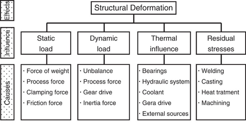
The economic demands on increasing productivity and minimizing tool wear are divergent, particularly if the time-consuming dressing processes are considered. At increasing material removal rates, grinding forces increase and lead to higher loads on the workpiece. In addition to the quasi-static strain, comparatively much higher strains caused by unstable and increasing dynamic process forces can occur. Figure 4.38 shows a comparison of process behavior in pendulum and creep-feed grinding of silicon nitride ceramic (SL200BG) caused by significantly different dominant wear mechanisms at the single grains. While profile deviation as a geometrical characteristic can be evaluated on the machined workpiece and postmachining carried out if necessary, changes in the wheel topography and unstable process behavior with increased risks of damage cannot be detected without complex measurement equipment. An evaluation of the state of wear based on machine tool integrated acoustic emission signals is suitable only in rare cases. The effect of wear on the process must therefore be taken into account.
Figure 4.38Process behavior of creep-feed and pendulum grinding of in consequence of different dominant grinding wheel wear types (creep-feed grinding: abrasion; pendulum grinding: microscopic splintering)
4.5. Cooling lubrication
Eckart Uhlmann, Günter Spur
Introduction
To reduce the mechanical, thermal, and chemical stresses in the active zone between the tool and workpiece, cooling lubricant is used in grinding processes. The two main functions of cooling lubrications are the dissipation of heat and the reduction of friction through lubrication.
Secondary functions include the chip removal, the cooling of the workpiece, grinding wheel, and machine tool, as well as the enhancement of the workpiece quality and the reduction of processing costs by decreasing tool wear. Furthermore the cooling lubricant cleans the active zone, the grinding wheel, and the machine tool of worn grinding tool particles [36–44].
Cooling Lubrication Systems
Cooling lubricant systems used in industrial production can be set up in individual or central designs. They consist of a number of components such as the cooling lubricant itself, the circulation system with feed and cleaning devices, the storage tank and accessories. To reliably fulfil their functions, all components of cooling lubrication systems must be adjusted to one another.
Cooling Lubricant
The composition of the cooling lubricant is essential for establishing suitable cooling lubrication conditions. Cooling lubricants are characterized by type, base oil, additive, concentration, and state. The characteristics determine the efficiency of the cooling lubrication. In addition to the main functions already listed, the following requirements must also be fulfilled [39]:
• Human and ecological compatibility (toxicity, smell, dermatological compatibility)
• Age and bacterial resistance (stability)
• Ability for filtration and recycling, mixing behavior, emulsifiability
Non-water-miscible and water-mixed cooling lubricants are used in grinding processes [43,45]. Non-water-miscible cooling lubricants include mineral oils and esters that do not need to be mixed with water to fulfill their function. Additives enhance the lubricating effect, age resistance, and corrosion prevention and reduce fog formation.
Examples of water-mixed lubricants are ready-made mixtures from concentrate and water, mostly solutions and oil-water emulsions. The concentrations vary between 2% and 6%, but for some applications they reach up to 20%. In water-mixed lubricants, functional additives can be included. In this case, sufficient wetting power of the medium must be ensured [39].
Supply, Circulation, and Purifying Systems
Supply devices ensure the delivery of the required cooling lubricant to the active zone of the grinding process. The efficiency of the cooling lubricant feed is greatly influenced by the design and the arrangement of the nozzle as well as jet velocity and volume flow rate. The circulation system ensures the delivery of cooling lubricant in the specified condition to the supply devices in the working room of the machine tool and the recycling of used cooling lubricant. For this purpose, containers, pipelines, channels, pumps, and other storage and conveying elements as well as measuring and regulation devices are required. In order to maintain the cooling lubricants in their intended condition, further components such as monitoring systems become necessary. Monitoring systems indicate the condition of the cooling lubricant using adaptive characteristics (the pH-value, electric conductivity, and continuously and discontinuously operating maintenance devices). These systems include ventilating, tempering, and purifying devices that can be integrated into the cooling lubricant circulation through a main or secondary stream [46,47]. To ensure the functionality of the cooling lubricant, special attention must be paid to its cleaning and purification.
Because it is impossible to clean cooling lubricant using magnetic grate separation for ceramic particles and due to particle diameters of sometimes dp < 3 μm, sedimentation technologies can only be used for coarse purification [39]. Flotation, filtration, and centrifugation techniques as well as combinations of these processes are used for purification in ceramic machining [39]. Even though filtration is the most conventional purification technology, band-pass and candle filters are the most common filter designs. In simple plants, band-pass filters are utilized as pure gravity filters. Vacuum filters are used to increase the quantity of throughputs, whereas an improvement of filter fineness can be achieved by usage of candle filters and filter accessories. Brücher demonstrated the potential of new purification devices such as alluvial, gravel, and full-jacket centrifuges for the machining of ceramics [39].
Auxiliary Attachments
Additional components such as suction plants, metal clads, mixing devices, and chip or grinding sludge concentrators, as well as emulsion separate units count themselves among the accessory devices. The application of cleaning jets to purify the grinding wheel topography in ceramic machining is, in comparison to metal machining, uncommon because clogging of the grinding wheel topography is unusual in ceramic machining. Should cleaning of the topography be necessary, the application of different technologies, such as continuous in-process-sharpening, is preferable [49–51].
Impact of Cooling Lubricants and Feed Conditions on the Process
Influence of Cooling Lubricants
Investigations of pendulum grinding of ceramic materials with diamond grinding wheels show advantages regarding the surface quality and process behavior using grinding oil instead of water-mixed cooling lubricants. When grinding Al2O3 and HPSN using water-mixed cooling lubricants, an increase in normal force with feed velocity is characteristic, while low and almost constant normal grinding forces occur up to a specific material removal volume of V′w = 780 mm3/mm using grinding oil (see Figure 4.39 ). Furthermore, grinding with grinding oil leads to a lower radial wear of the grinding wheel [39,48,52,53].
Figure 4.39Specific grinding forces, force ratio, radial wear, and average peak-to-valley height in relation to the specific material removal volume for water-mixed and nonwater-mixable cooling lubricants [57]
Considerable differences between the topography of A12O3 surfaces machined using grinding oil and the topography created by using emulsion show that the cooling lubricant has a significant influence on chip formation mechanisms. In contrast to surfaces that were machined using grinding oil, directional grinding traces scarcely arise on surfaces machined using water-mixed cooling lubricants [39,53–56]. These findings were confirmed for face grinding of an alumina reinforced with 10% ZrO2, for which different surface structures occurred, depending on the cooling lubricant used. Furthermore, the processes exhibited almost constant normal and tangential forces as well as lower grinding wheel wear when using grinding oil [37,55,56,58]. Other studies on face grinding of various oxide-ceramic materials indicated lower normal forces during cooling lubrication with petroleum or petroleum fog than with emulsion, emulsion fog, or compressed air. However, the lowest tangential forces as well as the lowest wear were measured using emulsion or emulsion fog. The used cooling lubrication had almost no impact on the attainable surface quality in these investigations. For face grinding of HPSN and AI2O3/TiC, deviating results occurred. In these cases, higher normal forces were measured using grinding oil instead of water-mixed cooling lubricants, which can be explained by the higher thermal stress on the grinding wheel. The grinding wheel wear, however, was lower for these materials using nonwater-mixable cooling lubricants [37,55,56,58].
Differences regarding grinding forces are rarely observed between water-mixed cooling lubricants of various compositions when face grinding A1203 + 10% ZrO2, HPSN, and A12O3/TiC. Yet, the grinding wheel wear was, irrespective of the material, slightly lower with an emulsion than while grinding with a solution [39,56].
Influence of the Feed of Cooling Lubricants
For pendulum surface grinding, creep-feed grinding, and cylindrical grinding, the influence of the cooling lubricant feed on the process and the grinding result was investigated [39,51]. Various nozzles were designed for this purpose, including an open jet nozzle, an enclosing nozzle, a nozzle as wide as the grinding wheel, as well as a squeezed tube with identical exit section. Due to the poor jet quality of the squeezed tube, which resulted in heavy air intake as a result of strong turbulences within the stream, the achieved cooling effect was strongly decreased for this nozzle. The increasing temperature weakened the bond of the grinding wheel, which resulted in excessive grain chippings and led to substantially higher grinding wheel wear and lower normal forces compared to the free jet nozzle (see Figure 4.40) [39,51,58].
Figure 4.40Specific normal forces, radial wear, and surface quality in relation to the jet quality for various feed pressures during grinding [39]
Although the feed pressure was increased, the technological disadvantages of the squeezed tube, especially regarding the grinding wheel wear, cannot be fully compensated for. If, however, the cooling lubricant pressure is increased from pKS = 0.2 bar to 10 bar with a simultaneous alteration of the volume flow for the free jet nozzle, a decrease in grinding wheel wear can be observed. With an increase in pressure, the total grinding forces, which consist of cutting forces and cooling lubricant forces that rise with pressure, increase strongly. If only cutting forces are considered, just a slight increase can be observed due to the fact that diamond grains remain in the bond longer at lower temperatures, and therefore pass longer friction ways under formation of stronger grain flattening [39]. At even higher pressures of pKS = 15 bar, a slight rise of wear is observed due to a deteriorated supply of cooling lubricant in the contact zone as a result of increased turbulences within the stream. The 4-point-bending strength decreases slightly with increasing feed pressure, which is traced back to crack-stop-effects at lower cooling lubricant pressures [39,51,52,57,59,60].
Considerable grinding wheel wear was observed for high-speed surface grinding of SiSiC with a cutting speed of vc = 100 m/s. The rise in wear can be explained by the insufficient heat removal due to the low cooling lubricant volume flow rate of Q′KS = 1.0 l/min mm in connection to an open jet nozzle. As a consequence, the synthetic resin bond was stressed above its permissible temperature limit. The excessive wear can be prevented by raising the cooling lubricant volume flow rate to Q′KS = 10.0 l/min mm to enable a higher heat dissipation at the contact zone. Similar to the preceding observations, the positive effect of increased volume flow rates is outweighed by rising jet turbulences at increased flow speeds, yet again resulting in increasing grinding wheel wear. The usage of enclosed nozzles led to a decrease of the grinding wheel wear below the level reached using the open jet nozzle at Q’KS = 10.0 l/min mm already at Q’KS = 5.0 l/min mm. Contrarily to the open jet nozzle, increasing the volume flow rate does not result in higher wear, but in a minor decrease. Obviously, the less turbulent and therefore more coherent stream emitted by the open jet nozzle penetrates the air cushion surrounding the grinding wheel more effectively and leads to a denser filling of the pore volume and hence to better adherence of the cooling lubricant to the grinding wheel. The result is a more effective heat removal from the contact zone. Irrespective of the nozzle systems used, the total normal forces increase as a result of increasing liquid pressure forces with increasing volume flow rates (see Table 4.6).
Table 4.6
Pressure in contact zone for different feed conditions [39]
Feed pressure
Pressure in contact zone pKS
pKS = 0.2 bar
pKS = 3.0 bar
pKS = 6.0 bar
pKS = 10 bar
Squeezed tube (APKS = 31.5 mm2)
0.53 bar
0.85 bar
0.96 bar
1.14 bar
Free jet nozzle (APKS = 22.5 mm2)
0.55 bar
1.40 bar
2.53 bar
3.92 bar
Ecological and Physiological Aspects of Utilizing Cooling Lubrication
Health Hazards
Contact with cooling lubricants bears the risk of cancer as well as respiratory tract and skin diseases, which can be caused by direct skin contact, swallowing, inhaling, or by contact with fogs and vapors [61–64]. Relevant substances for physical danger include emulsifying agents, which at times have a degreasing effect on the skin [65]; corrosion inhibitors, of which some are toxic and therefore should no longer be used [65]; preservatives such as formaldehyde [66]; and heavy metals. In particular, chlorine leads to chlorine acne and also causes issues in relation to correct disposal [63,65]. Additional health hazards arise from reaction products such as nitrosamines, microorganisms and their metabolic products [38,67], solid materials that can cause microdamages, dissolved toxic material elements such as nickel or cobalt, and personal hygiene [65,68]. The risk of skin irritation usually increases with a high pH-value and a rising concentration when using water-mixed cooling lubricants.
Ecological Damage
The use of cooling lubricants can lead to ground, air, and water contamination. Regarding their disposal and water damage, emulsions and solutions are most problematic. Due to their comparatively short service life, which is mostly limited by bacterial infestation, a relatively high quantity accumulates for disposal. The durability of alloyed mineral oils is longer, and possible service life depends on contaminations.
The lowest risk of ecological damage arises from biologically decomposable cooling lubricants such as esters, which can be characterized as ecologically neutral. However, lower disposal expenditures must make up for the often higher acquisition costs. In this regard an efficiency analysis is recommended for the selection of an optimal cooling lubricant under consideration of all limiting quantities, whereas criteria of the objectives should be mathematically combined with the capacity to fulfill these objectives [39,59]. An exemplary application of said efficiency analysis recommended the use of an ester as cooling lubricant based on its good ecological behavior [59].
Approach to the Reduction of Cooling Lubricant Volume
To solve the ecological, physiological, and economic problems caused by using cooling lubricants, the most promising step is to completely avoid the usage of cooling lubricants by dry machining. In addition to avoiding health hazards and ecological damages, the major advantages of dry machining are the avoidance of purifying, drying, or disposal processes for workpieces and chips, as well as the cooling lubricant itself, and therefore the saving of related expenses. These advantages lead to higher process flexibility and better recycling of cutting products [38,61–63,69]. However, these advantages are opposed by problems that result from the absence of the primary functions—cooling, lubricating, and rinsing—of cooling lubricants. For these reasons, dry grinding has only been applied in a scientific context until now [64,70]. Yet, a diminishment in the necessary circulation amount of cooling lubricant can be realized by optimizing the lubrication feed process in the active zone [38,61,62,71,72]. These optimizations are mainly accomplished by improved nozzle designs and adjustments (e.g. needle nozzles, shoe nozzles, or Rouse nozzles). Another approach is transporting the cooling lubricant directly to the active zone by tool types with internal cooling [63]. In an extreme case, the necessary cooling lubricant is determined so precisely by minimal-amount cooling lubrication systems that it is completely used up through vaporization. The low amount of necessary cooling lubricant as well as the fact that the cooling lubricant is, due to its singular use, not in constant circulation through the system are the major advantages of this cooling lubrication technique. As a result, high expenses for the control, maintenance, and disposal of cooling lubricants can be saved. So far, knowledge about the effects of cooling lubricant fog released into the air as well as corresponding countermeasures are not available however [61,71–77]. Additionally, significant quantities of cooling lubricants can be saved by discontinuous feed or delivery pumps regulated by the machine control system to exactly adjust the amount, time, and location of necessary cooling lubricant to the process. Furthermore, this technology allows a reduction of energy consumption [63].
4.6. Environmental issues
Michael Weismiller
Introduction
Manufacturing processes can be evaluated using four criteria:
The consideration of the human-environment technology condition is relatively new to the manufacturing industry. In many ways, investors and users of the technologies were not aware of many of the environmental hazards and did not provide enough resources to maintain minimum environmental standards. Over the past 10 years, however, government regulations, often the result of public opinion, have forced the manufacturing industry to account for environmental risks [80].
As the manufacturing industry has worked to protect the environment and employees from the effects of wastes, disposal costs have increased. Some examples of these efforts include formulating fluids to minimize harmful effects on worker health, extending the sump life of the grinding fluid, and minimizing the generation of waste by recycling [81].
Environmental Health and Safety
As with all metalworking fluids, grinding fluids can negatively affect worker health. Although respiratory effects may occur, occupational dermatitis (skin) problems are the most common. In fact, of all occupational diseases, approximately 50% are related to the skin [82,83]. One form of dermatitis is skin irritation and accounts for approximately 70% of the dermatitis cases. It is damage caused by skin exposure to the grinding fluid and is almost always curable. A second more severe form of dermatitis is skin sensitization (allergic) dermatitis and accounts for approximately 30% of the cases. It is damage caused by a worker’s allergic reaction to the chemical(s) in the fluid, is normally not curable, and may become worse with repeated exposure to the chemical(s) [84]. Unfortunately, the worker may need to be relocated to a different job to keep away from all exposure to the fluid [85].
The chemical properties of the grinding fluid and contaminants may lead to many of the skin irritation problems. For example, the grinding fluid is basic and has a pH of approximately 9. This level can irritate human skin, which has a pH of approximately 6. Grinding fluids also have chemicals (surfactants) that can remove the oil from workers’ skin, causing irritation with extended use. Bacterial contamination of the fluid can also irritate the skin. Finally, during the grinding process, metals (nickel, chromium, and lead) can enter into the fluid and irritate the skin [86].
Identifying and correcting skin irritation issues can be difficult because more than one cause may be to blame, or the issues may have resulted from the use of chemicals outside the workplace. For example, a rash may have resulted from working with the grinding fluid or from working in the garden (pesticides), working in the home garage (gasoline), using home bathroom cleaners, or using cosmetic products [82]. Also dry winter months can increase the possibility of dermatitis [83]. Therefore, employee hygiene and manufacturing site cleanliness and air quality are important factors in controlling dermatitis [84].
Many studies have been conducted to determine the respiratory effects of grinding fluids on plant personnel, but no definitive link to respiratory and pulmonary issues has been established. Researchers have suggested, however, that exposure to the mist generated in the grinding process may increase worker susceptibility to future respiratory problems [87].
Environmental Fluid Management
Even though the concept of fluid management has been around a long time, environmental regulations over the past decade have hastened a change in it. Now, the environmental hazards of grinding fluids are considered much earlier in the preparation of the fully integrated process. The environmental impact of the fluid becomes an important consideration in any environmental fluid management program [88,89].
A fluid management program must take into account any significant chemical changes that can occur in the grinding fluid that will increase cost and affect productivity. For example, the grinding fluid is a formulated mixture of many chemicals, several of which may become depleted over time. Changes in chemical composition can cause increased wheel wear, corrosion, demulsification, and many other performance issues. A number of contaminants can also cause a host of problems if they are allowed to enter the grinding fluid [90,91]. For example, metal particles produced by the grinding process can cause wheel wear and surface issues. Additionally hydraulic oils and tramp oils can leak into the sump, dilute the grinding fluid, and promote the formation of bacteria.
As stated earlier, water-based grinding fluids are known to be susceptible to microbial attack. Bacteria and fungi can breed in the water phase of the fluid and collect on machine surfaces. Researchers have concluded that the growth of microorganisms (bacteria, fungi, etc.) is one of the major reasons for grinding fluid failure. A relationship between microbial contamination and human health risks continues to be explored. Additionally, bacteria growth can result in offensive odors, corrosion of the machine and workpiece, fungus in lines, and deterioration of the fluid. A related issue is the growth of mold on building materials. Stachybotrys chartarum (also known by its synonym Stachybotrys atra) is often referred to as “black mold” or “toxic black mold.” It is frequently associated with poor indoor air quality that arises from fungal growth on water-damaged building materials [92]. When the S. chartarum mold spores in the air drop on wet or damp material with high cellulose and low nitrogen content, these spores can grow. Often growth occurs on cellulose building materials such as fiberboard, gypsum board, paper, dust, and lint, and in places subject to excessive moisture. Other materials such as dust, paints, wallpaper, insulation materials, drywall, carpet, fabric, and upholstery can also support mold growth. Constant moisture is required for its growth, which can result from water damage, excessive humidity, water leaks, condensation, water infiltration, or flooding.
Mold growth in buildings, whether it is S. chartarum or other molds, indicates that excess moisture is present and is the first problem that needs to be addressed. Mold growth can be removed from hard surfaces with commercial products, soap and water, or a bleach solution of no more than 1 cup of bleach in 1 gallon of water [93]. Mold in or under carpets typically requires that the carpets be removed. Once mold starts to grow in insulation or wallboard, the only way to deal with the problem is by removal and replacement. In areas where flooding has occurred, prompt drying out of materials and cleaning of walls and other flood-damaged items with commercial products, soap and water, or a bleach solution is necessary to prevent mold growth. (Note: Never mix bleach with metalworking fluid, cleaners, or ammonia.)
The microorganisms can be controlled by using the correct concentration (if water-based grinding fluid), prevention of the contamination of the fluid with swarf or organic materials, and routine cleaning of the line and sump. Based on these considerations, the selection of the fluid is critical. The grinding fluid must have the correct properties for the grinding operation, have the required sump life, and be able to withstand the recycling process envisioned in the environmental fluid management program.
Recycling of the fluid can be accomplished in several ways, such as mechanical separation and mechanical filtration. Because of growing disposal costs, mechanical separation through the use of centrifuges and hydrocyclones is finding increased use in environmental fluid management programs. Centrifuges use centrifugal force to separate small particles from the grinding fluid. Centrifugal separators can remove tramp oil and solids. Both require less space than other cleaning processes. Hydrocyclones are conical vessels into which used grinding fluid can be pumped tangentially. The solids are thrown to the walls and removed from the bottom of the vessel, and the clean fluid is removed from the top.
Another method to recycle grinding fluids is through filtration. Filtration systems are designed to remove liquid and solid contaminants from the grinding fluid by passing the grinding fluid through filter media that catch the particulate matter. Filtration systems are available in a range of sizes and throughput and can use pressure filters, vacuum filters, or gravity filters.
Filters also can be permanent, disposable, or made of inorganic mineral filter media. Permanent media filters can be made of metal belts and screens. They can be cleaned by backwashing and cut down on the amount of industrial waste. Disposable media filters can be made from cotton, paper, and synthetic fibers. They must be check regularly, and when blocked they must be disposed of as industrial waste. Manufacturing sites are using more reusable plastic filters to cut down on waste. Inorganic mineral filter media, such as diatomaceous earth, are extremely effective in oil systems, but can remove the emulsifiers and other components of grinding fluids [94].
Conclusions
In conclusion, in recent years the public and government have required the manufacturing industry to apply more resources to the protecting the environment and their employees from the effects of the use of grinding fluids and industrial waste. The use of higher-quality grinding fluid processes to decrease waste, increased worker hygiene, better plant cleanliness, and improvements in air quality have increased the costs of manufacturing, but have reduced the negative effects of the fluids on the workers and the environment.
Some examples of these efforts are formulating fluids to minimize harmful effects on worker health, extending the sump life of the grinding fluid, and minimizing the generation of waste by recycling.
4.7. Surface formation mechanisms in ceramic grinding
Eckart Uhlmann and Christoph Sammler
Introduction
The surface formation of abrasive machined ceramic materials results from multiple single-grain cutting edges penetrating into the workpiece material. In contrast to metallic materials, ceramic materials do not exhibit macroscopic plastic deformation behavior. According to ceramic material specifications, ceramics exhibit plasticity only on a micro level [95–97]. Thus the material removal and chip formation as well as the surface and subsurface formation must occur differently to metallic materials, which can be seen in the resulting surface topographies and the shape of the removed chips [95,98]. The surface topography is defined through the kinematic process parameters, the material properties of the workpiece and grinding wheel specifications (grain size and shape, grain concentration, bond specification and properties, and base body properties). The demands on the surface integrity of ceramic products, such as monocrystalline silicon as a substrate material for semiconductor production, are extremely high [99,100]. These integrities are normally not attainable through abrasive processes with bonded grinding tools, and time-consuming finishing processes are required. In order to minimize the extent of the necessary finishing processes, premachining with bonded grinding tools must provide a workpiece with a minimal damage depth.
For nondestructive surface characterization, conventional surface roughness parameters as well as residual stresses can be measured. Due to the mostly brittle material properties of ceramics, destructive characterization methods can be applied, such as the analysis of generated cracks and crack systems, using TEM-(transmission electron microscope) or FIB-(focused ion beam) and cross-section polish analysis, fretting fatigue tests, and flexural strength measurement.
Surface and Crack Formation Mechanisms Under Quasi-static Load
The idea of crack and surface formation and removal mechanisms in the grinding of brittle ceramic materials was developed in 1975, based on quasi-static indention tests on brittle material surfaces with differently shaped indenters and the resulting stress distribution within the test piece [101,102]. Under the requirement of a quasi-static load of a sharp point indenter (see Figure 4.41), the crack formation in brittle ceramic materials takes place in following steps (Figure 4.42): [101,102]
1.
Formation of an inelastic deformation zone is caused by a sharp point indenter.
2. At a certain threshold, a deformation-induced flaw develops into a small crack, termed a median vent.
3. At increased load a stable growth of the median vent results.
4. At the beginning of unloading, the median vent begins to close.
5. Sideways extending cracks, termed lateral cracks, occur when the indenter is removed.
6. After complete removal of the indenter/load, a lateral vent growth to the surface is possible and, potentially, chipping can occur.
Figure 4.41Model for elastic-plastic indentation problem [102] and top view of plastic deformation after indention of micro hardness pyramid in gas pressure sintered silicon nitride (CERAMTEC SL200BG)
Figure 4.42Mechanisms of vent crack formation under punctual load [101,102]
A precondition of this behavior is a microplasticity of the ceramic material, which is also used for micro hardness measurements (see Figure 4.41) [103].
Surface Formation at Scratching and Grinding
In addition to these quasi-static considerations, models for the determination of surface formation mechanisms under conditions comparable to those in a grinding process were developed in single-grain scratch tests. In particular, the single-grain chip thickness, identified as one of the significant parameters, in conjunction with the kinematic parameters, with a major influence on the mechanisms, can be defined in this experimental setup. Considering the microscopic fracture and crack formation behavior, the chip formation of brittle materials can be separated into three phases as shown in Figure 4.43[104].
Figure 4.43Model for brittle material removal [104]
Based on the microscopic plasticity and macroscopic brittleness, ductile and brittle components of chip formation can be observed. The respective proportion of these components acting at any given time results from the geometric engagement conditions, undeformed maximum chip thickness of the single grain, single-grain shape or rather cutting-edge shape, and the material properties itself. Uhlmann identified the critical stress intensity factor KIc to be the major influencing material property [14]. Lower critical stress intensity factor KIc correlates to lower proportions of ductile component of chip formation.
Initially, with the first contact of grain and workpiece surface, an elastic deformation of the grain–workpiece system occurs and frictional heat is generated. With increasing chip thickness, plastic deformation and the induction of cracks begins. In contrast to quasi-static indenter tests, the relative movement of the grain causes tangential forces and consequentially shear stresses. When a certain penetration depth is reached, particularly lateral cracks are formed and lead to shell-shaped or flake-shaped chipping on the damaged workpiece surface. The chip thickness and in particular the chip width can thus be larger than theoretically possible through volumetric overlapping.
With increasing grain size (leading to a higher negative rake angle), the dominant removal behavior can change from brittle to ductile [95,105,106]. In addition to grain size, the scratch velocity can affect the removal behavior and thus the surface formation mechanisms significantly. In scratch tests with various scratch velocities, the thermal conductivity of the workpiece material was determined by Uhlmann to be the most influential material property on the material removal mechanisms [95]. Depending on the thermal conductivity of the material, both increasing brittle or increasing ductile compounds of chip formation with increasing scratch velocity can be observed. Increasing scratch velocities lead to a higher thermal load and combined with a low thermal conductivity of the material, increasing the quenching effects occur that can lead to shell-shaped or flake-shaped chipping and the induction of cracks and crack systems in the boundary area of the engagement path.
In grinding processes, an increased cutting velocity and constant infeed and workpiece velocity usually lead to a better surface quality, which indicates that the removal mechanisms exhibit higher ductile components, resulting in higher specific grinding energies [107,108].
In order to minimize the boundary layer damage through brittle removal and surface formation mechanisms, models were developed to estimate the critical chip thickness at which exclusively ductile grinding should be ensured, with the factor for surface damage Ψ, the fracture toughness Kc, the Vickers hardness H, and Young’s modulus E shown in equation (4.32)[109,110].
hcu,crit=Ψ⋅(EH)⋅(KcH)2
(4.32)
Based on the three phases of chip formation and material removal, the damage mechanisms and the individual capability of the material for plastic deformation, it can be concluded that roughness parameters alone are not sufficient for the determination of the maximum damage depths. Based on scratch tests and TEM-analysis of scratched and creep-feed-ground workpieces, Uhlmann [95,111] summarizes the mechanisms of surface formation into three groups, shown in Table 4.7.
• Primary mechanisms resulting from load/penetration of cutting edges into workpiece material
• Secondary mechanisms resulting from discharge/relief of strain by first cutting edge and stress from multiple contact of successive cutting edges
• Tertiary mechanisms: prevention of crack spreading in the case of materials with a high glass phase ratio
Material condensation Formation of obstructions Crack induction Brittle break-off of particles in front of and alongside the cutting edge (particle formation)
Plastification or melting of the material or material phases Ductile removal of material in front of the cutting edge (chip formation)
Secondary mechanisms
Mechanical stress
Thermal stress
Break-off of particles behind and alongside the cutting edge Induction of deep-lying cracks Spread of deep-lying cracks through multiple stress of successive cutting edges Break-off of particles after crack spread toward the workpiece surface
Crack spread through thermal stresses due to temperature gradients Induction of deep-lying cracks Blistering of ceramic particles after crack spread toward the workpiece surface
Tertiary mechanisms
Thermal stress
Crack stopping effects at thermally plastified grain boundary phases Crack diversion at partially plastified grain boundary conditions in surface-near areas
Considering a differential small workpiece area, the load phase, material compression, formation of dislocation, and crack induction happen within the first phase at the beginning of cutting edge penetration. When the (lateral) cracks reach the workpiece surface, particle breakout in front of and beside the cutting edge takes place. This phase is characterized by energy input and, depending on the coolant conditions, plastification of the workpiece material may occur. When the shear strength of the material is reached, ductile material removal can take place.
The secondary mechanisms result in the mechanical discharge of the material. When the cutting edge leaves the material, a stress imbalance in the deformed and undeformed material areas leads to formation of crack systems along with relaxation of the stress imbalance and particle breakout. Due to dynamic loading through multiple successive cutting edge contacts, the crack systems can grow up to the surface and lead to material removal.
The tertiary mechanisms counteract the primary and secondary mechanisms. They depend on the material glass phase ratio that can allow the relaxation of crack energy on partially plastified material grain boundary phases. Thus, the crack propagation is reduced.
4.8. Properties of ground surface
Suzuki
Introduction
The quality of high-performance ceramic components is mainly characterized through the steps of the production process of machining. The technical strength of ceramics differs considerably from theoretical, molecular strength. Mechanical strength concentrations, due to flaws and cracks, cannot be reduced by plastic deformations as known for metals. The failure of a ceramic due to strength concentration is characterized by randomly distributed flaws. Therefore, standard variations can reach 20% to 25%.
For an optimization of both efficiency of machining and strength of machined ceramic parts, the complex relationship between machining parameters, elementary mechanisms of material removal, and strength-controlling surface effects (or surface integrity) must be understood. The aim of this chapter is to clarify how surface integrity influences the strength of machined ceramics.
Strength Testing Methods
The most common strength testing methods are three- or four-point bending methods because of their simple specimen geometries and experimental arrangement. Other methods for static strength testing are the tensile test, C-ring test, and double ring test. Dynamic testing is almost uncommon for ceramics because of ceramics brittleness, except for high temperature fatigue testing.
Double Ring Test
The double ring test [112] uses circular or square ceramic plates that are forced by two different sized concentricity arranged rings (Figure 4.44). The nature of load is bending. The main advantage of this test is that chamfer effects do not influence the strength data. The linear elastic theory of plates evaluates the radial and tangential tensile strength in the inner region of the specimen:
Where, Ro is radius of outer ring, Rj is radius of inner ring, Rs is radius of specimen, and d is thickness of specimen.
Bending Tests
The most common strength testing methods for ceramics are bending tests. Figure 4.45 shows the principles and the bending moment lines of both testing methods. In 4-point-bending tests, the specimens are loaded at four bearing areas. In contrast to the 3-point-bending tests, the bending moment in 4-point-bending tests is constant without traverse strain between the bearings. Therefore, the material properties will be analyzed better because ceramics bending strengths depend on volumetric flaws, surface cracks, and residual stress. The moment stressed region in the 4-point-bending specimen is greater than in the 3-point-bending specimen. Therefore, bending strength determined by 3-point-bending tests can be higher than in 4-point-bending tests.
Figure 4.45Three- and four-point-bending tests
The geometry and measure of the specimen are standardized [113]. The sticks with rectangular cross-section are dimensioned as follows:
• length: l ≧ 45 mm
• width: b = (4 ± 0.1) mm
• thickness: d = (3 ± 0.1) mm
• plane parallelism: ±0.05 mm
The edges should be rounded off or chamfered.
The used specimen can be manufactured separately or from a big part. The minimum number of each kind of specimen is 30. The 4-point-bending strength σ4B is calculated by using the measured force Fmax:
σ4B=σt=3⋅Fmax(L−1)2⋅b⋅d2
(4.34)
Statistical Evaluation
The Weibull distribution of the bending test sampling can be fitted by the parameters m and σ0. To evaluate these parameters, the maximum-likelihood method can be used [114].
Influence of Grinding Conditions on Ceramics Strength Behavior
Grinding Direction
Many components can be ground parallel or perpendicular to the stress direction. Fracture of ceramics originates from machining flaws as well as from material intrinsic failures. The strength degradation effect of micro cracks in the surface of ceramics can easily be understood by equations of fracture mechanics. The stress necessary to propagate a micro crack is given by the following equation:
σB≍KICY1√c
(4.35)
While KIC is the fracture toughness of the material, Y refers to the crack geometry and c gives the crack length. In view of their strength, the grinding direction should be parallel to the stress direction because perpendicular ground stressed components can be strength-reduced up to 30% to 40% (see Figure 4.46). This strength degradation can be explained by the different geometric crack distributions. The large surface longitudinal cracks lead to lower fracture strength than the smaller surface radial cracks.
Figure 4.46Influence of machining direction on the strength of brittle materials
Influence on Grinding Condition Compared to Lapping
Figure 4.47 shows the strength of HPSN for different machining conditions. Besides conventional grinding, creep-feed and multistage grinding are used as well as lapping. Compared to creep-feed grinding, the other machining process leads to lower bending strengths and Weibull modulus because of the process-induced crack population [115].
Figure 4.47Influence of the machining process on fracture strength
Process Model and Strength
The setting and system quantities of the grinding process influence the strength of machined ceramics. Most of the investigations found that the grit depth of cut has an important role in grinding [116]. A correlation is found between the grit depth of cut and the strength degradation in cup grinding of silicon nitride. The variation of the grit depth of cut by varying the grit size of the diamond wheels, the cutting speed, and the feed speed induced different stages of surface integrity. The influence of grinding conditions on bending strength and Weibull modulus of machined alumina ceramic is shown in Figure 4.48.
Figure 4.48Influence of grinding conditions on bending strength and fracture probability of silicon nitride
4.9. Grinding machines
Suzuki
Introduction
Ceramic parts require narrow tolerances for dimensional, form and position on deviations, and specific microgeometric and physical surface states. These requirements are due to the typical application fields and the material properties. Often, ceramic parts are chosen to meet high mechanical, thermal, chemical, and tribological loads. On the other hand, the specific sensitivity of many ceramics against tensile stresses and spot-like loading necessitates the control of dimensional accuracy to a higher level than by using ductile or tensionless endangered materials. These dimensional accuracy and surface integrity requirements must be considered when grinding machines are designed or installed. Up to now, grinding machines applied to ceramic parts have mostly been designed for machining of ductile metals. The adaptation of machine tools to the requirements of ceramics calls for the optimization of several functional units of a machining system:
• Machine structure
• Guiding system
• Spindle system
The drives and control units require some modifications but are generally compatible to the modern type of design. The machine periphery like the clamping devices, the measuring and sensory system, the balancing device, and conditioning system for the tools must be adapted to the machining of ceramics.
Machine Structure
The structure of a machine tool, comprising the body, the slides, and tables has two main functions [117]:
• To ensure the geometric position of the accuracy-determining components of the machine
• To support against forces and moments
This functional system is influenced by some disturbances that lead to deviations between tool and workpiece. These influences can be summarized into four groups (Figure 4.49).
Figure 4.49Structural deformations and their causes
One of the main disturbing effects is caused by thermal-induced deformations. This so-called “thermal stability” is of special importance in automatic fine finishing because the position of the workpiece to the grinding wheel normally changes by the thermal deformation of the machine structure.
Thermal deformations 1 result in the simple case of uniform temperature distribution 9 proportional to the length of a component according to the linear coefficient of elongation on α as follows:
∆/=α1∆9
(4.36)
In nonuniform temperature fields, even though additional bending and tilting takes place, the effect is normally much more severe. Figure 4.50 shows the deformation of a surface grinder resulting from the influence of temperature field. This may be caused by the front bearing of the spindle. First, it warms up the spindle stock, which moves in the negative Y-direction because of the clamping at the upper part of the spindle stock. Later, the column is also warmed up but only partly at the front side, which generates a bending deformation of the column. Thus, the typical movement of the wheel against the workpiece over time takes place as shown in Figure 4.50.
Figure 4.50Typical deformation, time, and causal connection
The main heat sources in grinding machines are as follows:
• Abrasive process
• Electric motors
• Spindle bearings
• Hydraulic system
• Cooling system
To minimize the effect of temperature fields in the machine structure, passive or active actions can be taken (Figure 4.51). Passive measures must be introduced when the machine is designed, for instance by removing heat sources from critical areas of the structure or by providing compensating elements in the structure. Active actions influence the energy flux in the body by cooling, heating, or compensating deformations via the numerical control of the machine.
Figure 4.51Actions against the thermal deflection
Another disturbing influence results from static loads. As mentioned before, the ratio between normal and tangential force, or the thrust and cutting force, respectively, in grinding is much higher than in cutting, that is, in turning or milling (Figure 4.52). The highly negative rake angles come from average abrasive grains that are relatively worn and thus show a flat shape. The chip generation in machining of ceramics leads, furthermore, to a substantial increase of the force ratio from about 4:1 in grinding ductile metals, to 10:1. The high normal forces bring high thrust deformations that directly influence the accuracy of the machine. Therefore, the static stiffness normal to the active surface of the grinding tool is particularly important for grinding machines applied to ceramics.
Figure 4.52Force ratio in abrasive machining
Besides the accuracy, the productivity of a machine is a concern. The high thrust forces bring deviations of the effective position against the nominal position of the tool. These deviations are normally compensated by spark-out dwelling (Figure 4.53). The spark-out time depends on the thrust force and on the stiffness of the system. The stiffer the machine, the shorter may be the spark-out period, which can be followed from the time constant T [118]. The static stiffness of the structure is dependent on its material and the design of the components in the flow of force.
Figure 4.53Elastic deformation of a grinding machine
Figure 4.54 gives some material data that are of interest for static loading of a structure. Because of economic reasons, the choice of materials is limited. The stiffness therefore has to be reached by design measures. For given material properties, the lowest compliance shows components that are loaded by pure tension or compression only, because the material cross-section receives a uniform stress distribution and is thus used most effectively. In machine tool structures, bending and torsional loading situations cannot be avoided. Figure 4.55 shows that the form features of components open an additional degree of freedom to influence the stiffness. The figure gives relative weights, bending, and torsional stiffness values in comparison to a square profiled beam. In the case of bending, the axial momentum of area is to be maximized. The distance of the material from the bending axes must be as large as possible. The double T cross-section is most favorable. In the case of torsional loading, the polar momentum of area is important. Additional effects can be reached by three-dimensional design components. The cross-sectional profiles with diagonal ribs or closed cross-sections with maximal diameters yield the highest stiffness.
Figure 4.54Properties of materials
Figure 4.55Stiffness of structure elements
In general, the structural elements of a machine body are not prismatic beams but are cross-sectional changes. Here, it is important that the flow of forces is smooth, because the introduction of transversal forces into flexible walls has a significant weakening effect. The same is true for joints in the flow of forces. They can be stiffened by prestressing.
Accuracy and productivity are also influenced by the dynamic behavior of a machine structure. It has to be distinguished between enforced or externally excited and self-excited vibrations (Figure 4.56). Enforced vibrations follow the excitation force or an exciting movement in their frequency. Excitations may be generated from unbalance, from periodic forces of the grinding process, from hydraulic pressure or volume oscillations, and from drives.
Figure 4.56Vibrations in machines
Grinding wheels rotate with high speed. In general, their mass is not exactly concentric to the axis of rotation. A small eccentricity, or small angle, occurs between the principal axis of inertia and the axis of rotation, or centrifugal forces generated by the imbalance act on the bearing system. If the rotor is disk-like, it may be balanced statically, meaning that the axis of inertia and the axis of rotation can be brought together by applying one compensation-mass. If the rotation system has a considerable length—as for instance, a broad wheel for centerless grinders—or if the disk-like wheel tumbles, the rotor must be balanced at least in two planes in the so-called dynamical balancing mode [117].
For static balancing, the rotating mass m with the eccentricity eμ must be compensated by a balancing mass u on the radius rμ.
eμ⋅m=u⋅rμ
(4.37)
The allowable eccentricity eμmax m is defined for rotors of the same type.
It is inversely proportional to the angular frequency.
eumax⋅Ω=const
(4.38)
The following quality classes are defined:
G 2.5: eμmax · Ω ≤ 2.5 mm/s for machine tools in general
G l: eμmax · Ω ≤ 1.0 mm/s for grinding machines
G 0.4e eμmax · Ω ≤ 0.4 mm/s for high precision grinders
In order to compensate in imbalances, balancing devices are applied. The different operational methods can be classified by three functions. Each function involves different solutions (Figure 4.57). As an example, type 2.2.4 is used for automatic balancing. An accelerometer measures the vibration in amplitude and phase. These signals are used to actuate four values that lead fluid, such as coolant, into four chambers. As a result, a compensating mass is generated.
Figure 4.57Balancing methods for grinding wheels
The other balancing devices, mostly using the centrifugal action to detect the imbalance (detection mode 2) and an active compensation mode (mode 2), are applied when high surface quality (especially in grinding of ceramics) is required.
External excitation can also be caused by gears. For this reason, the main spindle of a grinding machine is driven via belts or directly by a motor whose rotor is fixed on the spindle. Besides the mechanical uniformity of the speed, magnetic constancy of the electric motor is necessary to avoid excitations.
Because enforced vibrations can principally be influenced from the outside, they are not considered as critical as self-excited vibrations. Especially in grinding of ceramics, the danger of chatter is high because of the heavy normal forces. The excitation is determined by the dynamic system itself—that is, the machine structure, the tool, and the workpiece. The system vibrates with one or several natural frequencies. This kind of vibration can be suppressed by influencing the vibrating system by increasing the damping. Such damping is not achieved so much by the material of the machine body because material damping only contributes to a minor extent to the total damping. The influence of joints and guideways is two or three orders of magnitude higher. A special effect is possible by using auxiliary mass dampers (Figure 4.58). The system must be turned on the critical frequency. The effective band width is limited. In the case of enforced vibrations, the minimal compliance is determining the dynamic stiffness: for self-excited vibrations, the minimal negative real part of the compliance is critical.
Figure 4.58Effect of an auxiliary damper
Figure 4.59 shows the influence of a damper fixed to the workpiece support. It consists of an auxiliary mass, a bending beam as a spring, and a high absorption material that is loaded in shear. This measure doubled the dynamic stiffness at the working spot. As shown in the figure, the development of amplitudes at the workpiece could not be suppressed but could be retarded considerably by a factor of three [119]. The experiments are well reproducible; they were repeated four times. The scatter of the results was 12% measured in the time scale. The effect can be further increased by directly applying the damper to the workpiece, which is not always possible; but in many applications when using an arbor, the damper can be built in. Another typical measure to pass chatter problems in the grinding of ceramics is to use grinding wheels with high material damping.
Figure 4.59Influence of auxiliary damping systems in grinding
Guideways
Guideways determine the linear movement of a machine component like a table or slide in one direction and hinder movements in the other 5 degrees of freedom. The guiding function is disposed to several disturbing influences from which the requirements for guideways can be derived (Figure 4.60).
Figure 4.60Disturbing influences and demands on guideways
Guideways should be protected against swarf of the workpiece and particles from the tool, especially in the grinding of ceramics because the work particles have diameters down to micrometers or less and are highly abrasive. Sliding guideways may be worn out quickly. Antifriction guideways can also be disturbed by rolling the abraded particles into the guiding surface. Even for hydrostatic bearings, close protection is necessary to avoid pollution of the oil. Several means are available to protect guideways (Figure 4.61). They may act as scimmers or as covers. The accuracy and lifetime are greatly influenced by these protective devices.
Figure 4.61Particle protection devices
Guideways can be distinguished according to the kind of force transmission between the moving partners as follows:
• Sliding guideways (slideways)
• Roller guideways (rollerways)
• Hydrostatic guideways
Slideways work in the mixed friction domain: partly solid friction and partly fluid friction takes place. Normally, the traveling speed is not so high that a pure hydrodynamic state can be reached. For ceramic grinding machines, it is important that the travel of the wheel against the workpiece is exactly performed as dictated by the control and the drive of the machine. In addition, the guiding system must not show stick-slip behavior (Figure 4.62), otherwise small engagements will not be brought through from the driving system to the working point. The precondition to avoid stick-slip is that the friction coefficients of movement and standstill are equal, which can be achieved by polymer sliders, such as reinforced poly-tetra-fluoro-ethylene (PTFE). These layers on one side of the guideways solve the stick-slip problem for slideways. Because of the continual low pressure between the sliding surfaces—the weight of the workpiece and the process loads are normally of minor importance—guideways are often designed according to the sliding principle. This solution is also fairly inexpensive. The slideways may be built in an open form as prism-flat or prism-prism versions (Figure 4.63). The prism-flat design is considered as statically determined, though slideways consist of larger matching planes. The friction characteristics of the two guideways are different because of the wedge behavior of the prism. This situation is avoided by two prisms, although the design is statically overdetermined and can be overcome by giving a floating freedom to one of the prisms.
A sophisticated technical solution for linear guiding systems is hydrostatic guideways. Oil is pressed by an external source into the gap between the moving partners. The guiding surface is divided into several pockets that must be hydraulically decoupled to enable the system to carry eccentric loads. Often, capillary hydraulic throttles are used to obtain this decoupling effect. Stiffness and transversal damping abilities of hydrostatic guideways may be extremely high. The fluid friction force is almost negligible. The damping in the moving direction, therefore, may be critical when using path or position control loops. The systems are especially sensitive to pollution of the hydraulic medium. Hydrostatic guideways must be thoroughly protected against swarf and particles, especially when grinding ceramics. The system is dependent on the reliability of the hydraulic oil supply and is expensive compared to slideways or rollerways.
Rollerways contain balls or rolls as rolling elements. Their systems return the elements like roller chain, roller shoes, and others in which the rolling elements move against the guided table or slide. An important advantage of rollerways is that they are standardized and can be purchased from special suppliers. The stiffness is dependent on the number and diameter of rolling elements and especially of the preload. Prestressed guideways gain considerably in stiffness but also show higher friction. The damping ability is low compared to slideways or hydrostatic guiding systems. As mentioned earlier, the protection against swarf and particles is critical, especially in grinding ceramics.
Spindles
Generally, spindles are the most important components of a machine tool. They are located in the flow of force and determine the static and dynamic stiffness; thus they determine the accuracy and productivity of a machine tool to a great extent.
In grinding machines for ceramics, the design of the wheel-carrying spindle is of special interest. The high spindle speeds, high radial forces, and the required extremely low radial runout set specific demands. High dynamic stiffness is necessary to suppress self-excited vibrations as well as to minimize the vibration amplitudes in the case of enforced vibrations. Besides a high static stiffness, high damping values are necessary. These properties are mainly dependent on the bearing principles: hydrodynamic, hydrostatic, aerostatic, roller, or magnetic bearings (Figure 4.64).
Hydrodynamic bearings are fed by nonpressurized oil. The pressure distribution and its resultant force direction are dependent on the spindle speed. Thus, the bearing capacity, the stiffness, and the position of the spindle axis change with the rotational speed. For stationary conditions, the bearing shows a favorable behavior.
Hydrodynamic radial or axial bearings are normally designed with at least three pockets on the circumference to develop the necessary pressure fields. In the past, this type of bearing was typical for grinding machines because the spindle speed was mainly kept constant. Today, hydrodynamic bearings are still in use, especially for large spindle diameters. They have design features that enable pure fluid friction with low speeds.
A fluid layer of oil or air is generated between the rotating spindle and an outer ring. The behavior of these bearings is not dependent on the speed. In hydrostatic bearings, the oil temperature is critical for the performance because of the high shearing velocity in the fluid.
The oil should be temperature controlled to avoid thermal influences on spindle performance. Hydrostatic bearings are sensitive to pollution, so the spindle must be protected against the intrusion of chips and coolant, especially in machining ceramics where small abrasive chips are generated. It is obvious the costs for producing a grinding machine with a hydrostatic spindle are high. On the other hand, hydrostatic spindles show good performance concerning the radial deviation, maximum load characteristics, and damping characteristics. The radial and axial runout of such a bearing is principally low.
Aerostatic bearings are based on the same principle as hydrostatic ones but use air as a medium. This aspect limits the maximum pressure and the damping characteristics of the bearing. The advantage of gas as a medium is the reduction of friction (compared to oil), which enables high rotational speeds. Aerostatic spindles have low radial deviations below 0.01 μm. It is the best value of all spindle types. Because air is compressible, the maximum load that can be applied to the bearing is lowered, limiting the acceptable forces on the spindle. The damping rate of air is lower than oil. A lower damping rate, along with the density characteristics of gas, is the reason for the sensitivity of aerostatic bearings to self-excited vibrations. This spindle type is used for precision grinding operations at low loads. Typical examples include inner diameter cut-off grinding machines for slicing single crystalline silicon wafers and internal grinding machines.
The most frequently applied spindle bearings are ball bearings. As standardized parts, they are available in many different modifications at reasonable prices compared to other bearings. So-called antifriction bearings for spindles in machine tools can either be roller or ball bearing types. Roller elements have linear contact areas that are larger than the contact zones of balls with spherical contact. Ball bearings experience decreased friction compared to roller bearings because of their reduced contact area. Therefore, for higher velocities, ball bearings are applied with a reduced maximum load capacity. Figure 4.65 shows the ranges of rotational speed for different grinding operations, and the maximum speed for the different bearing principles. For the majority of grinding machines, angular ball bearings also capable of carrying axial loads are used. The load in a ball bearing is transmitted by a thin lubricant layer between the rings and the roller elements. A breakdown of this layer causes fatal damages to the spindle bearing. The lubricant of roller bearings can be realized by grease, which under normal conditions lasts the whole life cycle, by oil injection, and by oil mist for high speeds. High frequency spindles for small grinding wheel diameters generally use an oil mist because of its lower friction and decreased losses. Ball spindle bearings are regularly assembled with a preload to achieve close tolerances. Because of preloading and the thin lubricant layer, ball bearings have a good stiffness at low damping rates. The roundness deviation tolerances of these bearings depend on the quality of manufacturing and assembly of rings and rolling elements. For precision bearings, roundness deviations below 3 μm are realized. For higher speeds, so-called hybrid ball bearings can be applied. The rings of these elements are conventional bearing steel—for instance 52,100 according to SAE—and the balls are made from ceramics with lower density and thus lower centrifugal forces and favorable tribological properties. For the grinding of ceramics, an air pressure protection can be used to avoid the intrusion of dust and chips.
Figure 4.65Speed ranges and spindle bearings for grinding machines
Magnetic spindle bearings have been on the market for several years. The ferromagnetic spindle is carried by four magnetic fields. This kind of bearing is principally unstable; without further measures, the spindle would run off the center and contact the outer part. This effect must be suppressed by a closed loop control. Sensors measure the position of the spindle and, via the control circuit, influence the supporting magnetic fields. The position of the spindle is thereby stabilized. Additionally, the principle offers the possibility to measure forces or to tilt the spindle to compensate deflections. The main advantage of these bearings is low friction. Figure 4.66 shows the design of such a magnetic bearing. Magnetic bearings are only used for high-frequency spindles into which the motor is integrated. They can be applied for rotational speeds from 30,000 to 120,000. The possibility of adjusting the dynamic characteristics of the control loop provides the opportunity to fit the bearing stiffness to the process. Magnetic bearings have a constant maximum torque over the whole speed range. The main disadvantages of these types of bearings are minimum velocity (30,000 rpm) and the cost, which is several times higher than that of a ball bearing spindle.
Figure 4.66High-frequency magnetic spindle
Clamping Devices
The main function of a clamping device is to fix the workpiece in an exact position within the working area of the machine tool (Figure 4.67). Especially in machining of ceramics, the specific characteristics of the material require some special considerations [120,121]. The demands shown in Figure 4.67 can be fulfilled in different ways, as shown in Figure 4.68, for external and internal machining operations.
Figure 4.67Main functions of clamping devices
Figure 4.68Reduction of degrees of freedom by different clamping designs
The main focus of a clamping device is to ensure the workpiece position in translatory and rotary directions, which can be done either by a force-locking (magnetic chuck, vacuum chuck) or a form-locking device. In most applications, the clamping device is a combination force- and form-locking clamping device (multiple-jaw chuck, mandrel, etc.).
Different from metals, ceramics can only be deformed elastically within small limits. Furthermore, most ceramic materials are not magnetic, thus excluding the application of magnetic clamping devices that are used for ferrous materials. With these features, several characteristic demands on clamping devices arise as shown in Figure 4.69.
Figure 4.69Developing of clamping device for ceramic components
A main criterion is to avoid local load peaks that may lead to workpiece damage by crack initiation. Due to the high process forces in the machining of ceramics, simultaneously high clamping forces must be produced. To fulfill the high quality demands on ceramic components, precise clamping devices with high repetition accuracy are required. Furthermore, easy operation is required as well as high flexibility. One solution is to use locking clamping devices, which provide a flux of force over an extended area into the workpiece. Local load peaks can also be avoided by flexible intermediate media. Other solutions are vacuum clamping devices and indirect clamping, where the workpiece is glued to a metallic fixture or is clamped by well-known means [121].
In the internal and external grinding of ceramic components, mostly multiple-jaw chucks are used for workpiece clamping. A six-jaw precision chuck is shown in Figure 4.70. It is characterized by a high radial and axial accuracy of less than 2 μm and is also appropriate for the clamping of thin-walled workpieces. An adjustable pneumatic clamping force provides advantages in ceramics machining [122].
Figure 4.70Precision chuck
Figure 4.71 shows different types of clamping devices for surface grinding operations of ceramics as well as their range of application. Clamping shoes and bolt levers are often used in machining of metals. Because of the danger of load peaks in ceramics, only a few are suitable and thus are predominantly used for single-part production.
Figure 4.71Clamping devices for surface grinding operations
Vises are convenient in clamping workpieces with plane parallel faces. For ceramic materials, soft jaw materials such as aluminium or plastics can be used. Complex workpiece shapes can be clamped by modular clamping devices to provide high flexibility. Magnetic slide rails make it possible to clamp nonmagnetic, flat workpieces on surface grinder by loading them with an additional retaining force. Vacuum clamping devices offer similar possibilities such as magnetic clamping plates and are convenient for clamping flat workpiece shapes. For complex shapes in large-scale production, pouring the workpiece in and/or pasting it on a magnetic carrier plate are two methods of fixing.
Figure 4.72 shows two different clamping devices for the external grinding of ceramic slide-ring sealings. The flexible internal diameter device offers the advantage of center slide-ring sealings in a range of diameter of about 10 mm. By a hydraulic three-point centering of the inner diameter and by adjusting a nut in the axial direction, the slide-ring sealings are simultaneously clamped. The disadvantages of this system are high cost and difficult installation.
Figure 4.72Clamping devices for external grinding of slide-ring sealings
Internal diameter clamping devices fix the workpiece by the adjustment of a nut and an adapter ring. For slide-ring sealings with different internal diameters, only the adapter ring must be changed, while the same basic system can be used. The advantages of this clamping device compared to the flexible internal diameter system are easy assembly and low production costs.
Grinding Machine Topology
Surface Grinding Machines
Surface grinding machines for ceramics can be divided into (1) creep-feed grinding type and (2) reciprocating (speed-stroke) grinding type. Reciprocating grinding works with relatively small depth of cut and high speeds (up to 40,000 mm/min) and requires particular specifications of the driving system such as high damping and acceleration. On the other hand, creep-feed grinding works with large depth of cut (e.g., more than 1 mm). For this purpose, it is necessary to work with a low and smooth feed velocity of less than 60 mm/min. Because of the large depth of cut, the contact length is high, the number of cutting edges is large, and thus the normal force acting between wheel and workpiece is relatively high. As a result, surface grinders for creep-feed machining must have a high static stiffness against these normal forces.
Grinding spindle drives of surface grinding machines require steplessly adjustable numbers of rotation speed up to about 10,000 min–1. In dependence on the grinding wheel diameter, cutting speeds of about 400 m/s are achieved so that high speed machining conditions are reached. The spindle power of surface grinders depends on the field of application and may amount up to 80 kW.
Coolant supply of a surface grinding machine must provide high coolant flux (400 l/min) and high coolant pressure (300 kPa) to guarantee effective cooling of the workpiece and cleaning of the wheel. In combination with the small particle size of ceramic chips, high requirements also have to be met by the coolant purification system. Because oil is the common cooling liquid in ceramic machining, a completely sealed working area combined with an efficient suction of oil mist is required, in order to avoid danger of fire or explosion.
Furthermore, surface grinding machines can be sub-divided into three main types of construction: (1) the column, (2) moving column, and (3) transverse construction. An example of the column type grinder is shown in Figure 4.73. The design depicts a few characteristics for ceramic machining and provides a high-quality machined surface. By compact construction of the machine components as well as by using cast iron material for the machine bed, a high-static, dynamic, and good thermal symmetrical behavior is attained. A special device for trueing and dressing of diamond grinding wheels allows the application of the rotary trueing stones.
Figure 4.73Example of CNC surface grinding machine
A surface grinder in moving column construction is shown in Figure 4.74, which is also appropriate for ceramic machining. In addition, the machine is provided with an external cylindrical grinding device. The concept is based on the specifications required for utilizing CBN and diamond grinding wheels. The moving column travels on a central bed and carries the grinding spindle and the spindle motor. These machine components made of polymeric concrete assure high rigidity and good damping.
Figure 4.74High-speed grinding machine with external grinding device
The external feed drive device controlled by a CNC axis is developed for creep-feed grinding operations. The rotational speed is adjustable up to 25 l/min. A specific trueing device mounted on the top of the grinding wheel allows continuous dressing (CD) during grinding. Intermediate dressing with a table trueing device is also possible. Furthermore, the machine is fitted with complete measuring devices to record information on the workpiece, tool, and machine system [123].
Internal Grinding Machines
Small cylindrical halls can be ground by the internal grinding machine. A serious problem with internal grinding of ceramic workpiece is the machining of long bores with small diameter. Internal grinding can be subdivided into (1) longitudinal grinding and (2) plunge grinding. In internal longitudinal grinding, the wheel and workpiece move in parallel relative to their superficies. The infeed in the radial direction is carried in increments at the reversal points. In internal plunge grinding, the radial infeed is continuous. Modern internal grinders are designed to do both of the longitudinal and the plunge grinding. The requirements on an internal grinder for machining of ceramics are equal to other ceramic grinding machines. In general, internal grinding machines are characterized by low static and dynamic stiffness of the spindle system and the mandrels, which in total account for up to 90% of the overall compliance. These attributes affect workpiece accuracy and the internal grinding process itself.
Because workpiece tolerances of less than 2 μm are required for typical machined surfaces of ceramic components, the positioning accuracy of the machine feed axes must be 0.5 μm. This level can be reached by ball-screw feed drives combined with high accuracy measuring devices. The angle fault of machine swivel axes must be less than ±0.001°.
The grinding spindles of internal grinders for the machining of ceramics should also allow sufficient wheel speeds up to 60–80 m/s. This requires adjustable grinding spindles with a maximum number of revolutions up to 60,000 l/min (minimum spindle power: 7 kW). These demands can be met by high-frequency spindles with conventional or magnetic bearings. Magnetic bearings also offer the possibility to balance the spindle and the possibility to compensate the spindle displacement.
The workpiece in internal grinding should be adjustable in the range of 50–2,500 l/min. The feed velocity of machine axes in the radial and axial directions should be in the range of 5–8 m/min. This range is also adequate for the essential dressing feed velocity of grinding wheels used in the machining of ceramics. Internal grinders are usually built in flat-bed design. An example for a CNC-controlled machine is shown in Figure 4.75. This machine can also be used for external and face grinding operations. Its compact cast iron construction exhibits high static and dynamic stiffness, as well as thermal stability. Guideways of feed axes are free from backlash because of the thin and pretensioned ball-screw design. Prestressed bearings for the guiding of feed axes and ball screw feed drives with directly adapted servo motors guarantee high accuracy of feed motions.
Another construction principle is shown in Figure 4.76. The characteristic feature of this slant-bed construction is a 70° swiveled cross slide that supports the workpiece clamping device. The advantage of slant-bed constructions are high guide length (guiding in the area of engagement), easy flux of force into the bench, and the avoidance of pitching moments [124]. These characteristics are advantageous especially in grinding ceramic components because they withstand the high machining forces in the normal direction and guarantee high workpiece accuracy. The main disadvantages of a slant-bed construction are high construction costs and machine flexibility. These characteristics render this machine type more suitable for large-scale production.
Figure 4.76Schematic of a slant-bed construction
External Grinding Machines
The external grinding process can be subdivided into traverse and plunge grinding, as well as internal grinding as shown in Figure 4.77. In the traverse grinding the surface roughness of the workpiece is good; however, the efficiency is low. On the other hand, in the plunge grinding, the surface roughness of the workpiece is not so good but the efficiency is high. The plunge grinding can be applied to profile grinding by giving a profile to the wheel. An example for a CNC-controlled external grinding machine is shown in Figure 4.78.
The feed in the axial direction of the workpiece is carried out by the slide table or the grinding spindle headstock. The radial infeed is performed by the grinding wheel. Up to now, the industrial market does not offer any external grinding machine that is especially developed for the machining of ceramics. Therefore, the adaptation of single machine components will be the first step to fulfi1l the demands on the machining of ceramics.
Bench, guideways, and feed drives of an external grinder must provide the same features as the other machine types. Because of the high process forces in the normal direction, the critical component of an external grinding machine is the workpiece spindle characterized by its low stiffness. It can be raised by using prestressed conical-roller bearings or multiple-area hydrodynamic bearings. Another critical component is the tailstock for clamping the workpiece between centerpoints because of the high compliance. Therefore, especially in external grinding operations of ceramic workpieces, a stiff tailstock design is required. For that purpose, some machine manufacturers offer centersleeves with prestressed bearings or adjustable tailstocks. Another possible way to raise machine rigidity is to use workpiece spindle heads movable against a fixed tailstock. Spindle drives for external grinding are equipped with hydrostatic, hydrodynamic, or aerostatic bearings. At present, hydrodynamic bearings are mainly used. To meet the demands on the machining of ceramics, the grinding spindle must provide a high spindle power and a load independent of the revolution speed.
Centerless Grinding Machines
In centerless grinding, the workpiece
is held between two grinding wheels, rotating in the same direction at different speeds. One grinding wheel is on a fixed axis and rotates so that the force applied to the workpiece is directed downward. This wheel usually performs the grinding action by having a higher linear speed than the workpiece at the point of contact. The other movable wheel is positioned to apply lateral pressure to the workpiece and usually has either a rough or rubber-bonded abrasive to trap the workpiece. The relative speed of the two wheels provides the grinding action and determines the rate at which material is removed from the workpiece surface as shown in Figure 4.79. In the first of three types of centerless grinding, the through-feed type, the workpiece is fed through the grinding wheels completely, entering on one side and exiting on the opposite. The regulating wheel in through-feed grinding is canted away from the plane of the grinding wheel in such a way as to provide a lateral force component, feeding the workpiece through between the two wheels. Through-feed grinding can be highly efficient because it does not require a separate feed mechanism; however, it can only be used for a simple cylindrical shape.
Figure 4.79Mechanism of centerless grinding
With the end-feed type, the workpiece is fed axially into the machine on one side and comes to rest against an end stop; the grinding operation is performed, and then the workpiece is fed in the opposite direction to exit the machine. This type is best for tapered workpieces.
In-feed centerless grinding is used to grind workpieces with relatively complex shapes, such as an hourglass shape. Before the process begins, the workpiece is loaded manually into the grinding machine and the regulating wheel moved into place. The complexity of the part shapes and grinding wheel shapes required to grind them accurately prevent the workpiece from being fed axially through the machine.
Coordinate Grinding Machines
Typical applications of this universal machine type are the grinding of bores and contours of different shapes in a single setting. Typical components are cutting tools, jet molds, cans, dies, and molds. By a modern control concept, an efficient production process in single and large scale production is being assured. Using oil and emulsion as coolant lubricants gives the possibility to reach high grinding ratios. Because of the high accuracy of the machine components, good true-to-size, shape accuracy, and high surface quality can be achieved (Figure 4.80).
Figure 4.80Example of coodinate grinding machine
Coordinate grinding machines come with up to 6 NC axes. The basic axes are slide table, cross slide, and the spindle head. Further axes are the fine adjustment of the spindle eccentricity, rotation, and oscillation of the planetary spindle. Additionally, the number of NC axes can be raised by a rotary table. The universal behavior of a coordinate grinder and the specific construction of the machine require extremely high demands on the stiffness of each single machine component.
Insert Grinding Machines
Another special purpose in the machining of ceramics is the grinding of ceramic cutting inserts. For these applications, special machine tools have been developed. Figure 4.81 shows an example of cutting insert grinder used for tool manufacturing.
The heavy grinding unit with a bearing spindle is mounted on a separated beam cantilever and is able to oscillate on the upper machine body in a wear-resistant pivot bearing. Automatic oscillation of the grinding unit is accomplished via an eccentric drive, resulting is smooth and shock-free operation. The workpiece unit is swivel-mounted on the machine bed by an axial bearing for setting the desired angles. The swiveling is infinitely variable by a DC motor–driven tooth belt; thus, the whole system is free of play. Exact positioning is ensured by an electronic positioning control system.
The machine is provided with 6 CNC axes (X, Y, Z, A, B, C), with a resolution of 0.05 μm. The grinding spindle drives with a 20 kW motor and up to 8,000 min-1 allows high cutting speeds. The feed speed of the workpiece slide (max. 20 m/min) is generated by a DC motor via tooth belt and precision ball screw. In addition, the machine is equipped with a conditioning device for automatic dressing between grinding cycles, ensuring a high surface quality of the machined workpieces.
Cut-Off Grinding
In addition to grinding and finishing operations, the machining of ceramic components often requires cut-off processes. These processes can be subdivided into peripheral cut-off grinding and ID cut-off grinding [121].
The peripheral cut-off grinding process is subdivided into oscillation grinding with a stationary workpiece and rotational cut-off grinding where the workpiece is moving around its longitudinal axis. The main advantage of rotational cut-off in comparison to other techniques is the small contact length. Machines for peripheral cut-off grinding operations are the same as for cutting metals, hard metals, or glass. For special applications, an adaptation to the demands of ceramics is required. The machine settings in peripheral cut-off grinding depend on the work material. Cutting speeds from 20 to 45 m/s are common, as well as cutting depths of about 40 mm with feed speeds up to 1,000 mm/min [121,125].
ID cut-off grinding can also be subdivided into oscillating and rotational grinding. The characteristic feature of an ID cut-off grinder is the unconventional tool made of a high strength chromium-nickel steel; the internal diameter is electroplated with an abrasive layer. In order to assure adequate axial rigidity of the tool, the blade is tensioned like a drum-skin on its outer rim by a special clamping head (Figure 4.82). During cut-off, the rotating tool plunges with its active grinding profile into the workpiece at a certain feed speed [126].
Figure 4.82Scheme of ID cut off grinding
Common applications for ID cut-off grinding are cutting-off of bar-shaped and tubular workpieces, especially in silicon wafer production. Depending on the workpiece material and its diameter, the feed speed can reach over 100 mm/min, while the cutting speed is in the order of 25 m/s. The main advantage of ID cut-off grinding is a kerf loss of less than 0.5 mm.
Wire Cut-Off Grinding
Recently, cut-off needs of the Si and sapphire crystal are increasing. In wire cut-off grinding, an endless wire tool electroplated with an abrasive layer is utilized (Figure 4.83). The wire is guided, driven, and prestressed in the axial direction by four guide rollers. This relatively new machining concept for ceramic components allows cutting speeds up to 70 m/s. The radial feed speed increases to 15 mm/min. Wire cut-off grinding makes possible the cutting of complex contours. The disadvantage is the low stiffness of the wire vertical to the cutting direction, which causes wire deflection and reduced workpiece shape accuracy [121,125].
Figure 4.83Scheme of wire cut-off grinding
ELID Grinding
Electrochemical material removal (ECM) can be efficiently used especially for continuous in-process dressing of grinding wheels. The metal bond is continuously removed during the grinding process by electrolysis. Thus, the constant usage of sharp grits can be guaranteed. In addition, ECM will not damage the diamond grits. The coolant used in the grinding process also serves as an electrolyte for the ECM process. Rapid wear of the bond material can be avoided by a defined electrochemical process in the passive area of the electrolysis system [127]. The principle of ELID grinding is shown in Figure 4.84[128]. An oxide layer formation at the surface of the anode prevents excessive grinding wheel wear. The electrolysis will continue due to the mechanical removal of the oxide layer during grinding. With suitable process parameters, a dynamic equilibrium of oxide layer growth and removal will occur and result in stable dressing conditions, and therefore in a stable finish grinding process.
Figure 4.84Principle of ELID grinding
Micro/Ultraprecision Grinding
Demand continues to increase for the installation of microaspheric glass lenses in various optical and electric devices, such as blue laser DVD pickup devices and compact digital cameras, in order to improve the optical performance. Microaspheric glass lenses are molded by a glass press molding process with microaspheric ceramic molds made of tungsten carbides (WC) or silicon carbides (SiC). These aspheric ceramics are ground by CNC ultraprecision grinding machines with microresinoid-bonded diamond wheels. As the shape of the optics becomes smaller and more complicated, the grinding machine requires greater preciseness and multi-axis scanning. Figure 4.85 shows an example of recent multi-axis controlled ultraprecision grinding machines. This machine has four axes (X, Y, Z, C). The X, Y, and Z axes are linear motor driven with positioning resolutions of 1 nm. The work spindle and the grinding spindle are porous-type air-bearing with greater stiffness [131].
Conventional size (diameter: Φ5–Φ200 mm) of axis-symmetric optic mold can be ground by 2-axes controlled machine as shown in Figure 4.86. The grinding spindle is a vertical type, and the work spindle is horizontal. The wheel scans in two axes (X, Z) according to the NC program that calculates the wheel radius and aspheric constants. The thin disc shape of the diamond wheel is used, and the wheel edge is trued to be a small curve on the machine [129].
Figure 4.86Vertical type of aspheric grinding machine
In case of small or micro mold (diameter: Φ0.3–Φ5 mm), the wheel shaft has a risk of contacting the workpiece edge; the grinding spindle is 45 degrees tilted in order to use a much small wheel and overcome the problem as shown in Figure 4.87. In order to increase the grinding speed, ultra high grinding air spindle is used even though the small wheel is used. By using a diamond wheel of Φ0.3 in minimum diameter, the mold of Φ0.3 mm can be ground ultraprecisely. Form accuracy of 0.05 μm P-V and surface roughness of 2 nm Ra are obtained [130].
The microstructured Fresnel shape of the mold can be ground by the sharp-edged grinding wheel. A schematic illustration of the micro Fresnel grinding method is shown in Figure 4.88. For the wheel, a disk shape of diamond grinding wheel, whose edge is trued as a sharp knife-edge, is used. The wheel scans along the workpiece radial position vertically. The orientation of the wheel air spindle is vertical and the workpiece air spindle is horizontal. The feature of this grinding method is that the wheel rotates in parallel with the workpiece rotational direction at the grinding point. The axis-symmetric aspheric Fresnel shape of the mold can be generated by the sharp-edge grinding wheel. The sharpness of the wheel is important in order to generate the structured surface precisely. Form accuracy of 0.1 μm P-V and surface roughness of 2 nm Ra are obtained [131].
Figure 4.88Microstructured grinding of Fresnel shape

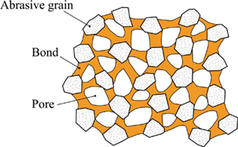
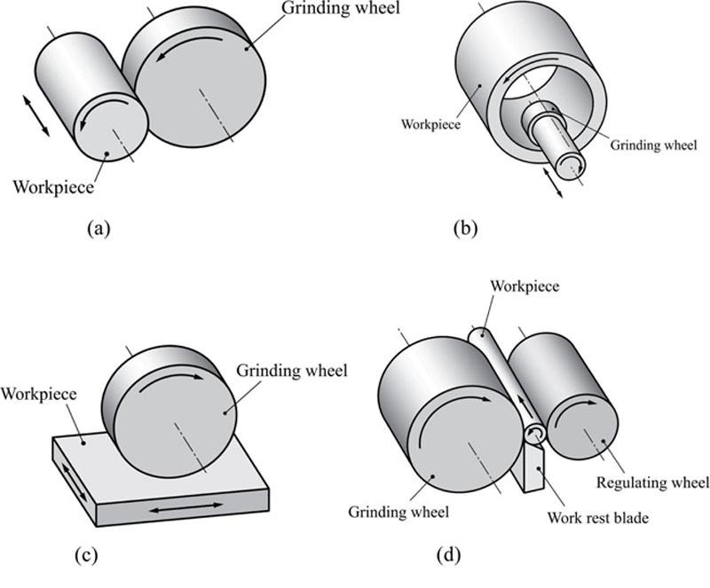
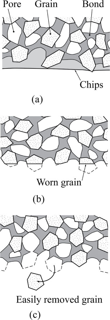
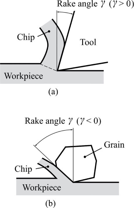
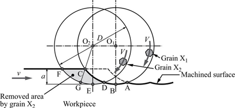

 (4.8)
(4.8) (4.13)
 (4.14)
 (4.15)
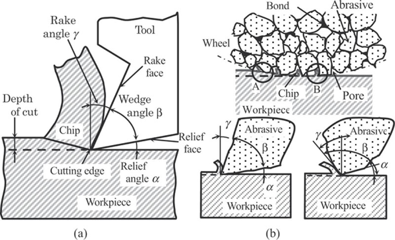
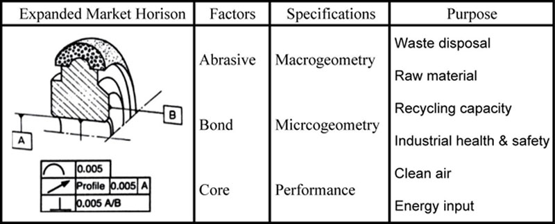
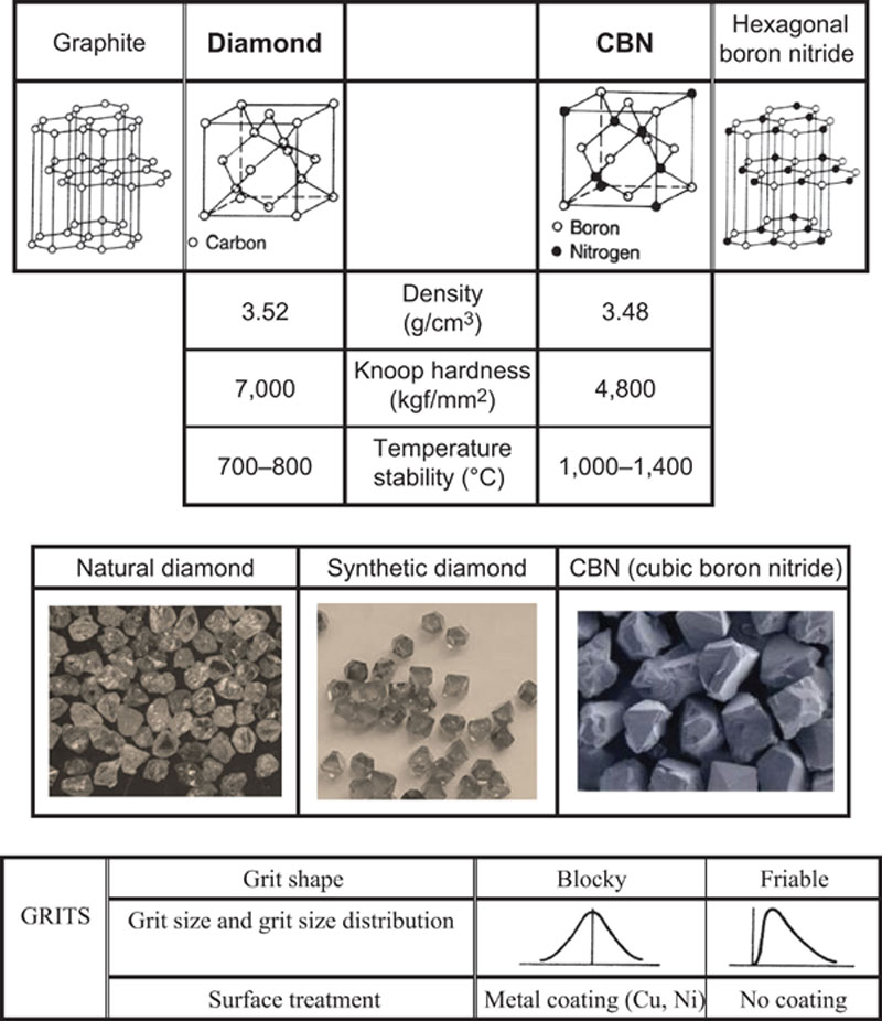
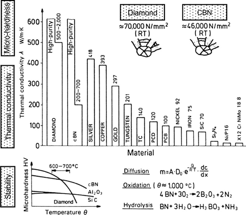
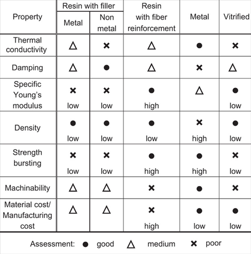
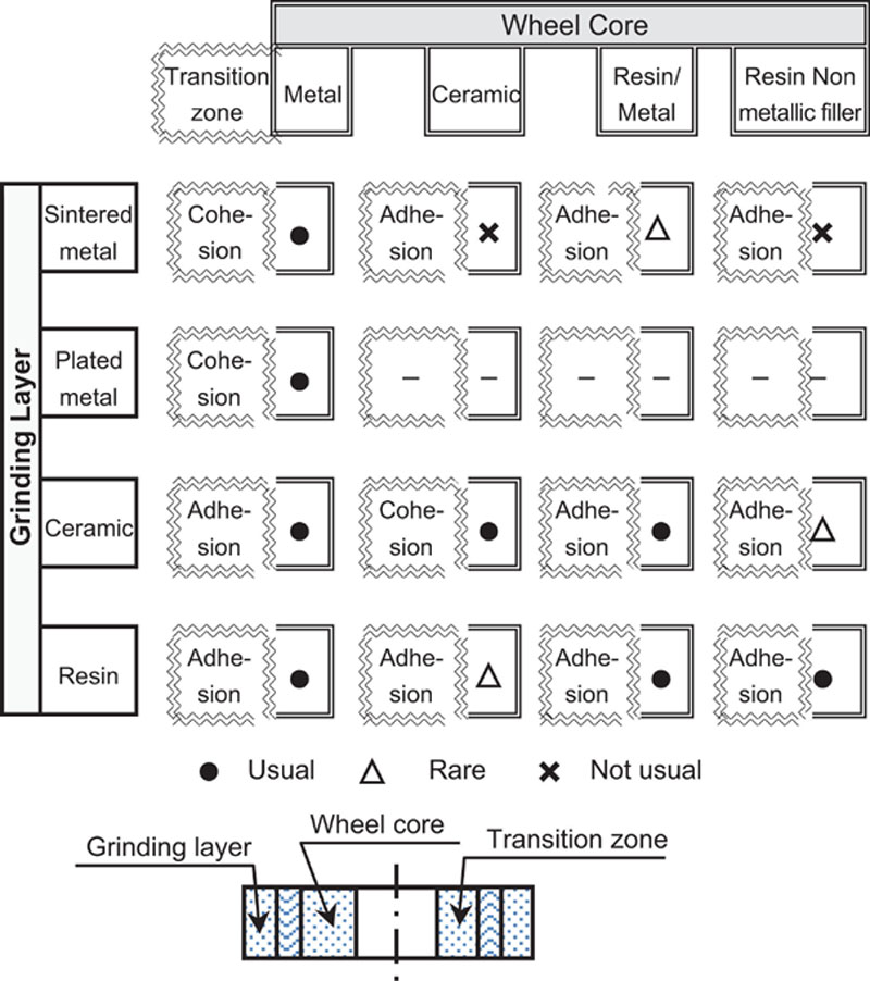
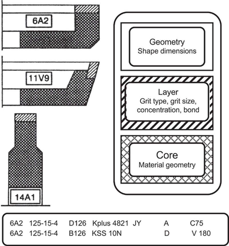
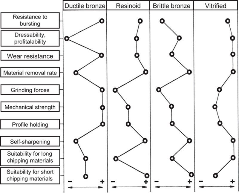
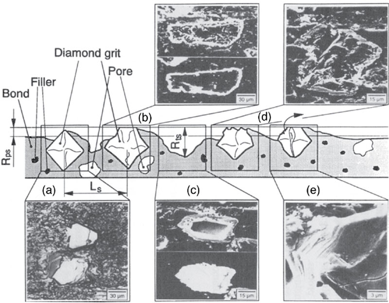
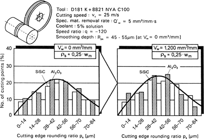
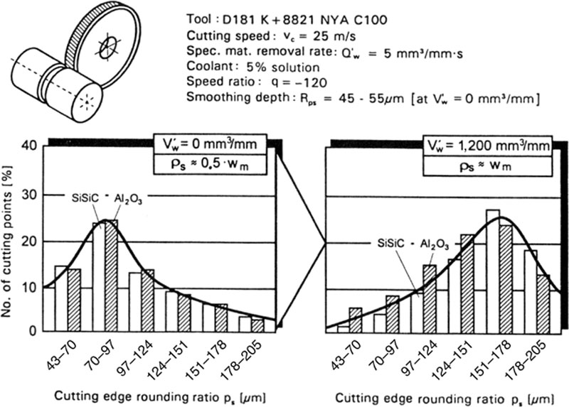
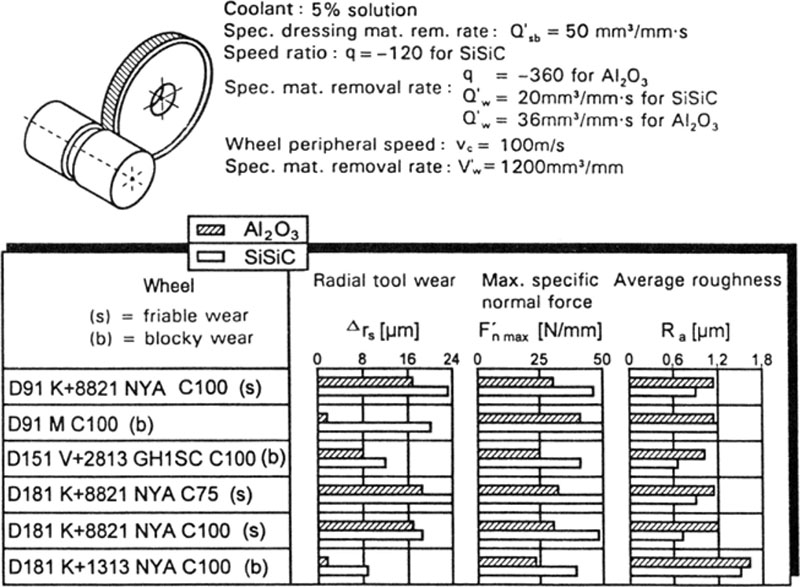
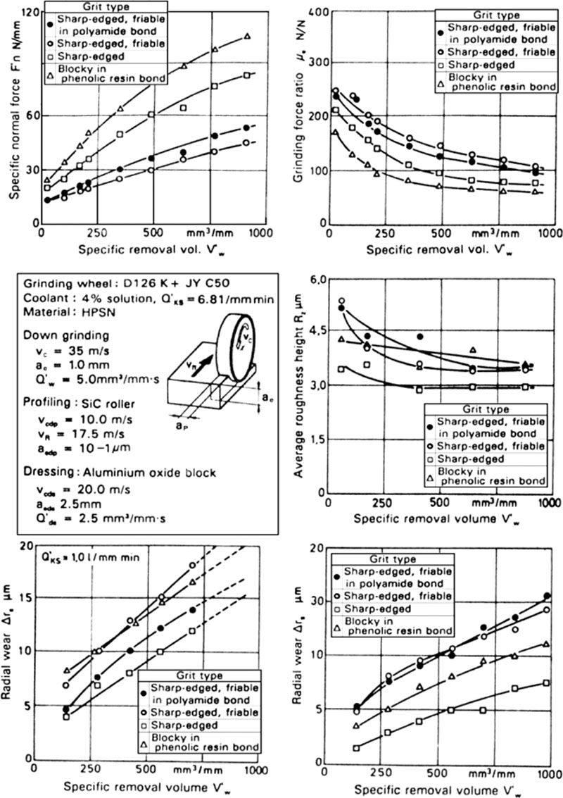
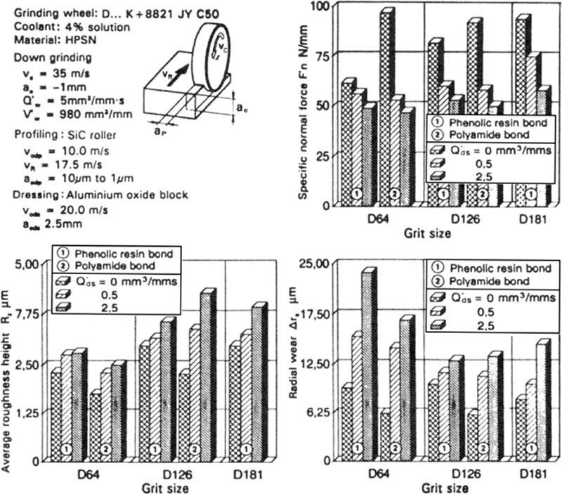
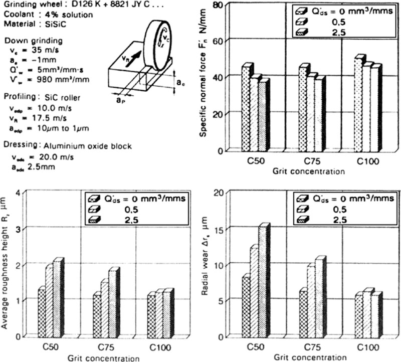

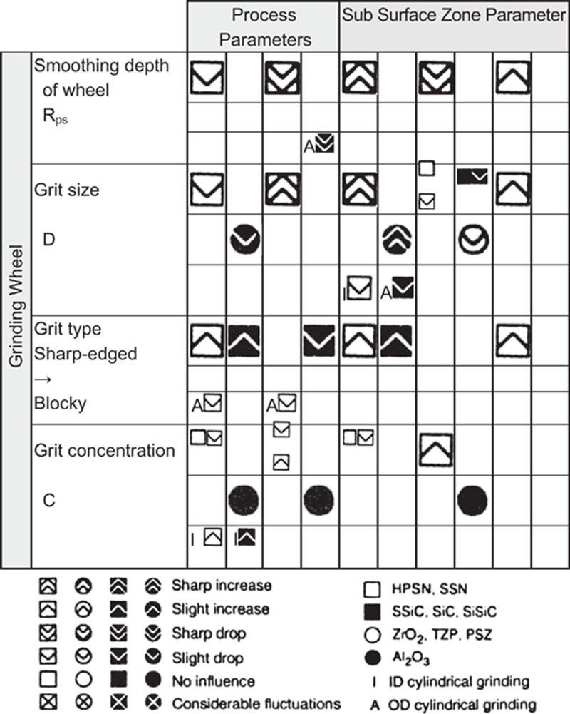
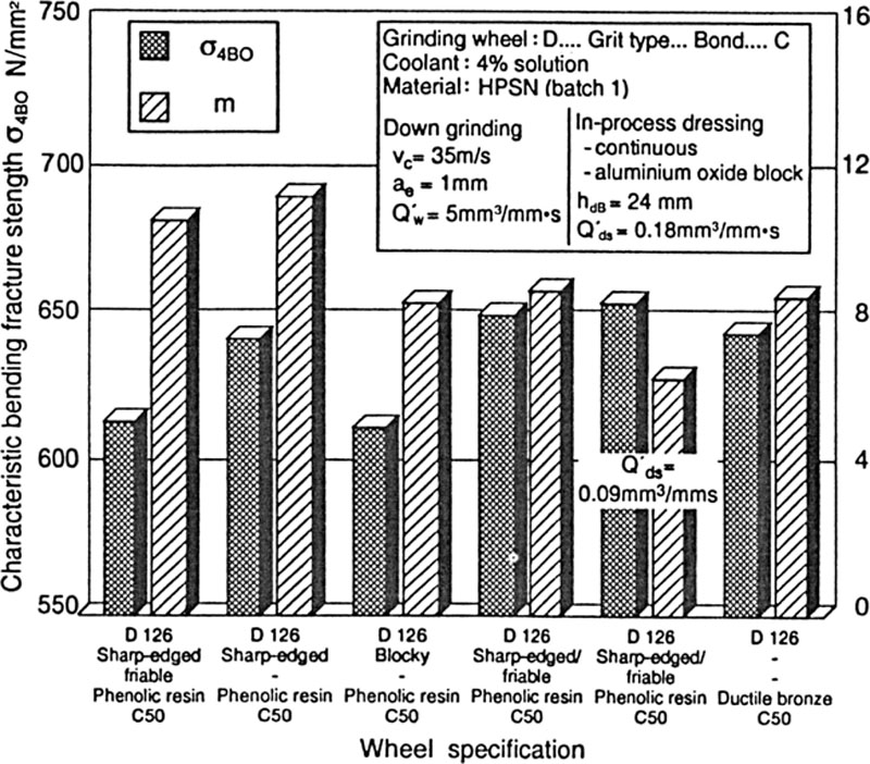
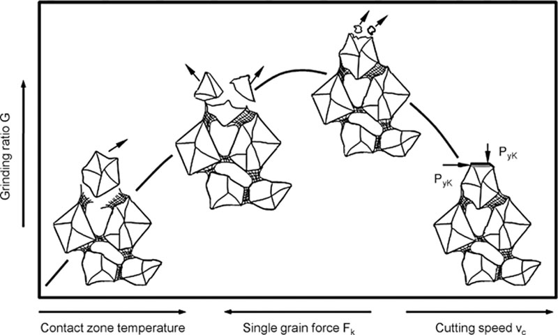

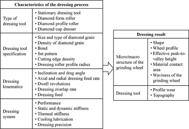
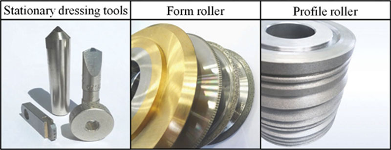
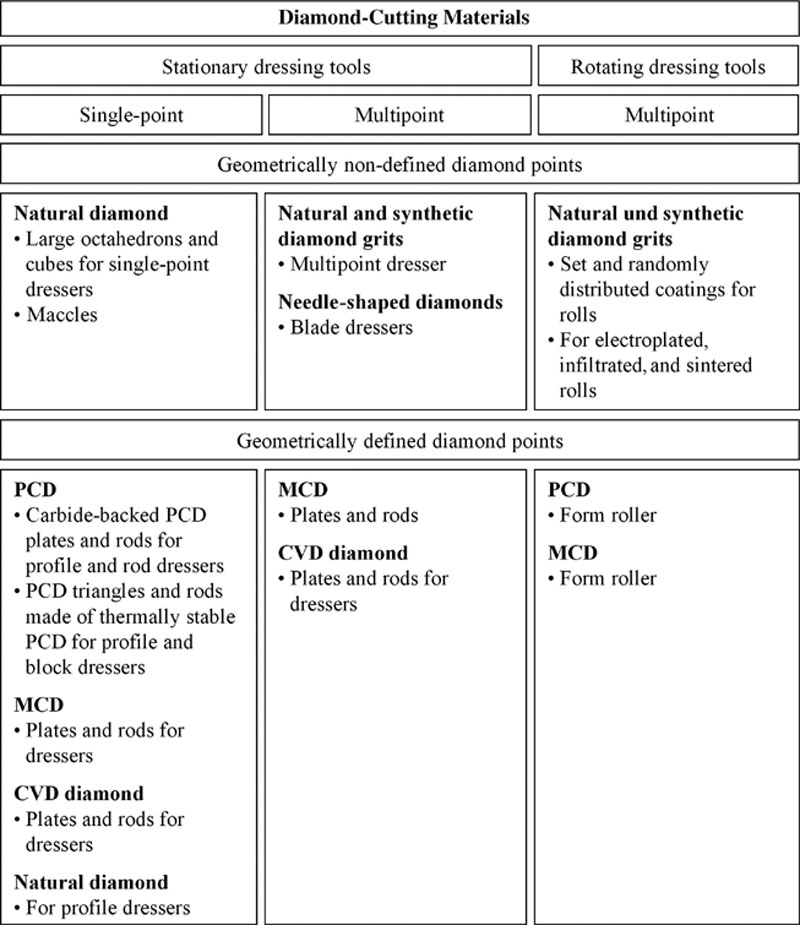
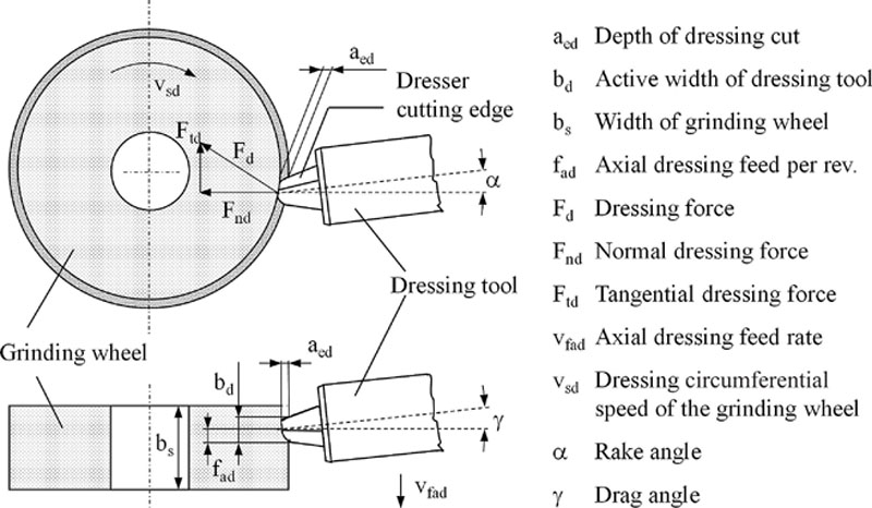
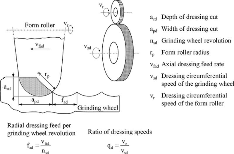
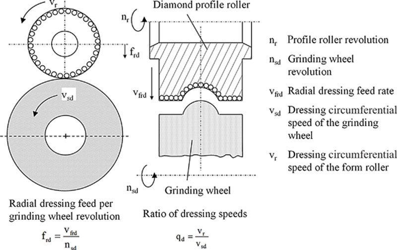
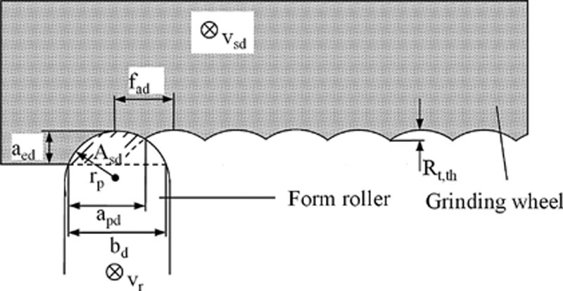
 (4.16)
 (4.18)
 (4.19)
 (4.20)
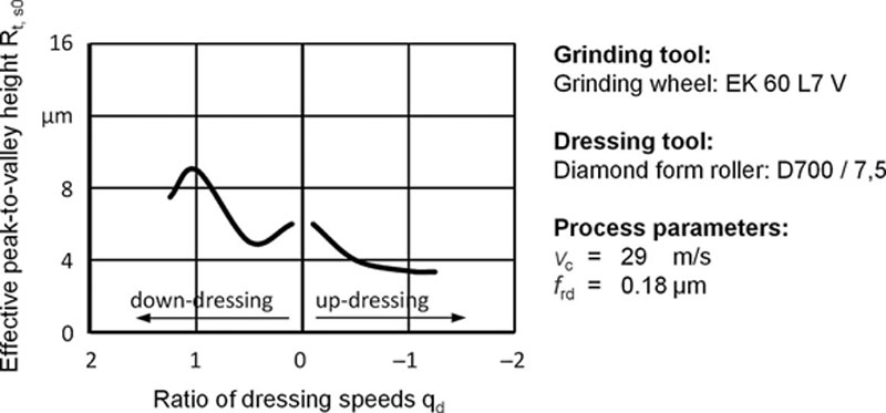
 (4.21)
 (4.23)
 (4.24)
 (4.26)
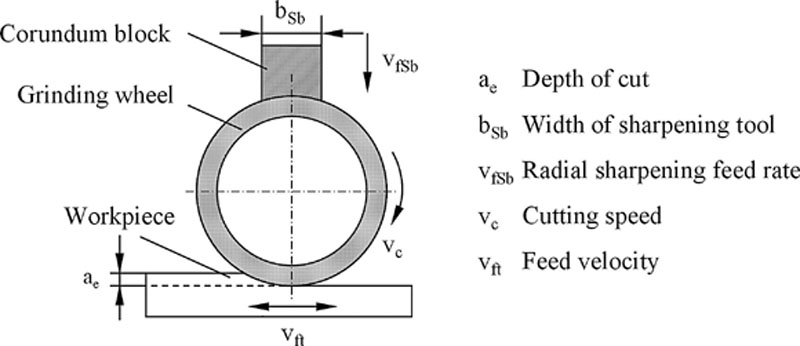
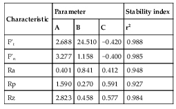
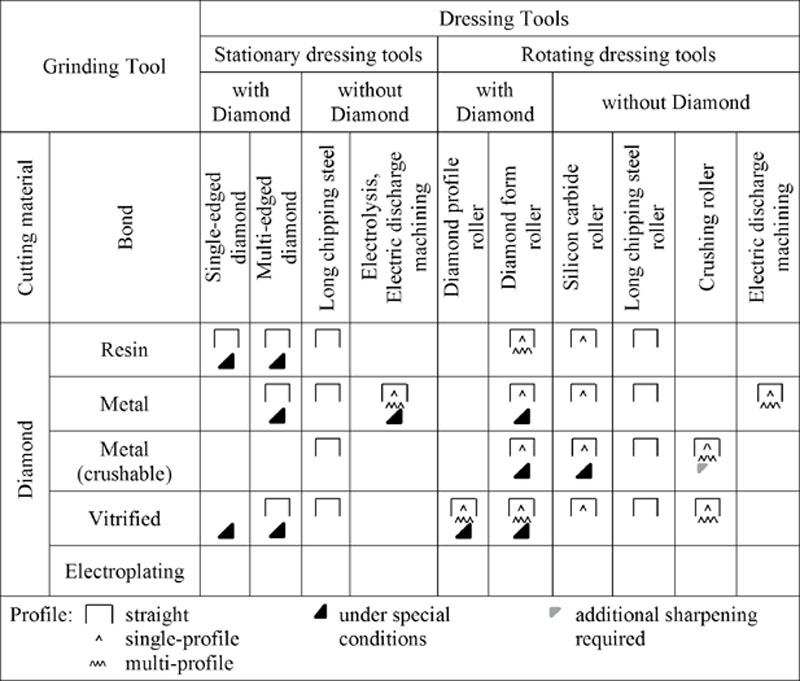
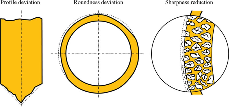
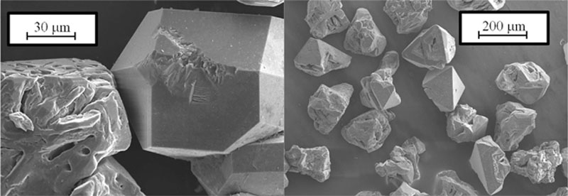
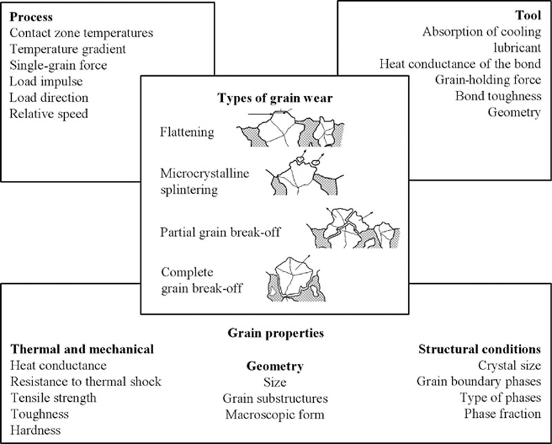
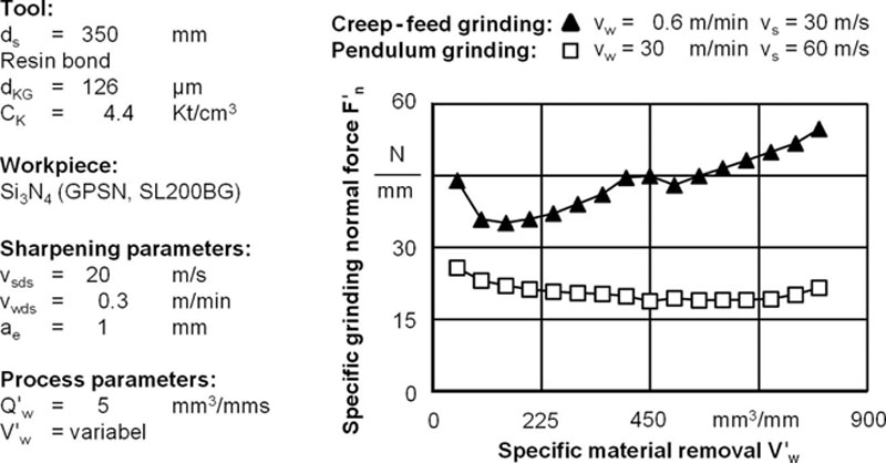
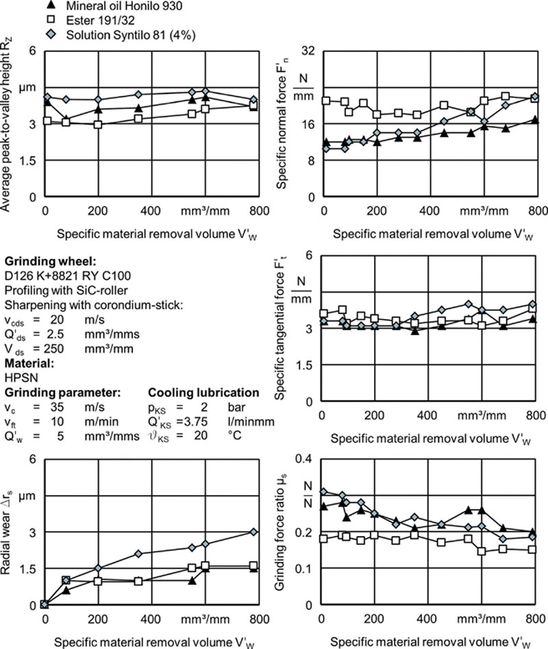
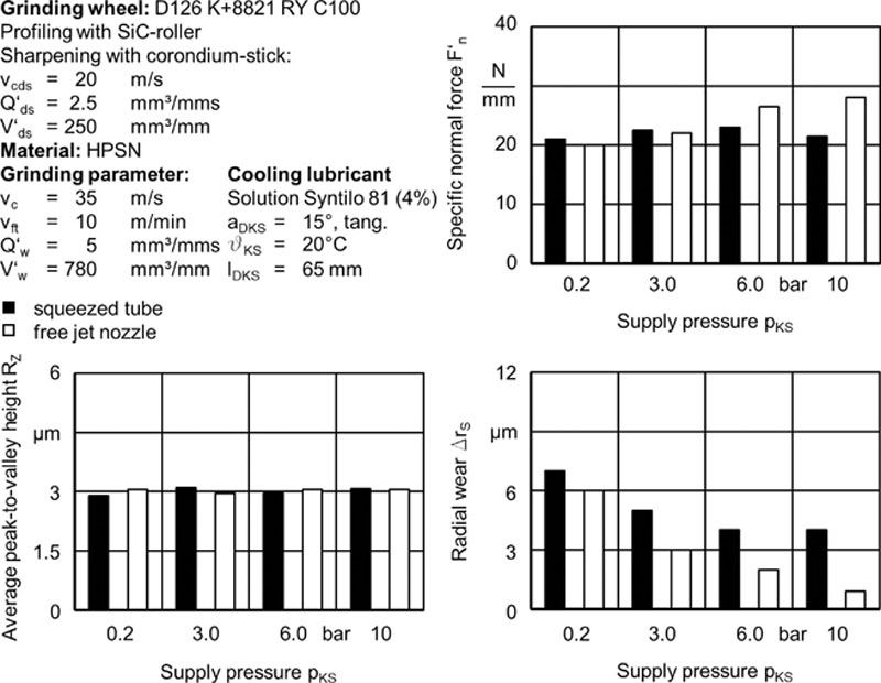

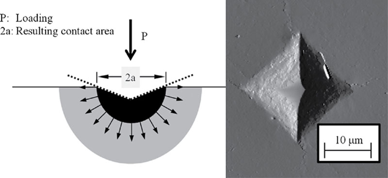

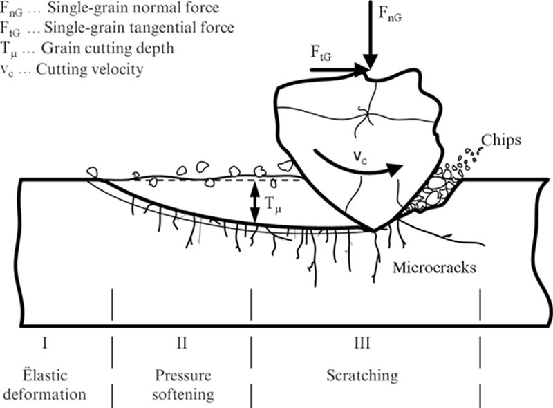
 (4.32)
 (4.33)
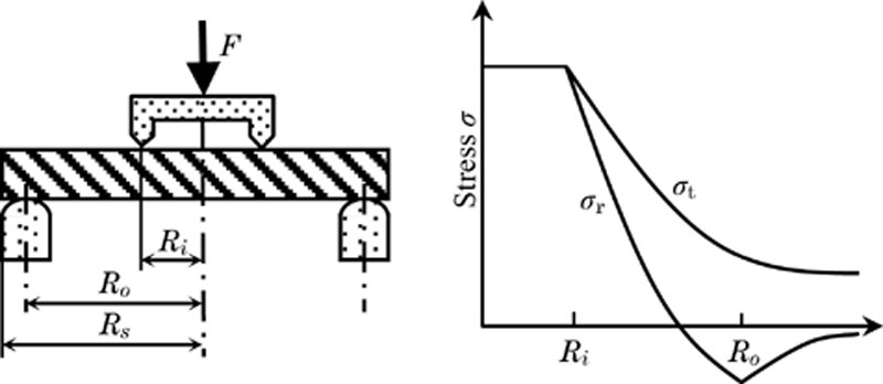
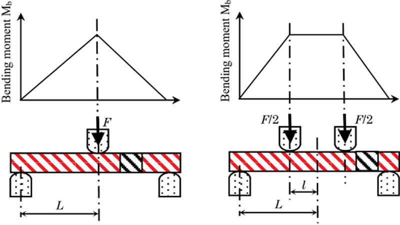
 (4.34)
 (4.35)