
9.5. Electrical Power and Lighting Systems
Rising energy costs and government regulations are some of the reasons why people are rethinking their energy consumption. Growing awareness of climate change and dwindling resources are other factors why energy efficiency is becoming increasingly important in everyday life. Fortunately, the production and transmission of electricity is relatively efficient and inexpensive, although unlike other forms of energy, electricity is not easily stored and therefore must typically be used as it is being produced. Electrical systems can provide a facility with accessible energy for heating, cooling, lighting, and equipment (telecommunication devices, personal computers, networks, copiers, printers, etc.) and appliance operation (e.g., refrigerators and dishwashers). It has witnessed dramatic developments of the last few decades, comprising the fastest-growing energy load within a building. More than ever, facilities today need electrical systems to provide power with which most of the vital building systems operate. These systems control the energy required in the building and distributes it to the location utilizing it. Most frequently, distribution line voltage carried at utility poles is delivered at 2400/4160 volts. Transformers step down this voltage to predefined levels for use within buildings. In an electric power distribution grid, the most common form of electric service is through the use of overhead wires known as a service drop, which is an electrical line running from a utility pole to a customer’s building or other premises, and it is the point from where customers receive their power from the electric utilities. However, it should be noted that there are currently several new building management programs on the market that are not only well suited to control individual systems but also allows one to integrate and intelligently link the many building disciplines from HVAC to lighting and shading systems, fire safety, power, and security.
In residential installations in North America and countries that use their system a service drop comprises of two 120 volt lines and a neutral line. When these lines are insulated and twisted together, they are referred to as a triplex cable. In order for these lines to enter a customer’s premises they must usually first pass through an electric meter, and then the main service panel which will usually contain a “main” fuse or circuit breaker (CB). This CB controls all of the electrical current entering the building at once, and a number of smaller fuses/breakers, which protect individual branch circuits. There is always a main shutoff switch to turn off all power; when CBs are used this is provided by the main CB. The neutral line from the pole is connected to an earth ground near the service panel; often a conductive rod driven into the earth. For residential applications the service drop provides the building with two separate 120 volt lines of opposite phase, so 240 volts can be obtained by connecting a circuit between the two 120 volt conductors, while 120 volt circuits are connected between either of the two 120 volt lines and the neutral line. 240 volt circuits are used for high-power devices and major appliances, such as air conditioners, clothes dryers, ovens, and boilers, while 120 volt circuits are used for lighting and ordinary small appliances. As these are only “nominal” numbers, it means that the actual voltage may vary.
In many countries around the world including Europe, a three-phase 416Y/230 system is used. The service drop consists of three 240 volt wires, or phases, and a neutral wire which is grounded. Each phase wire provides 240 volts to loads connected between it and the neutral. Each of the phase wires carries 50 Hz alternating current which is 120° out of phase with the other two. The higher voltages, combined with the economical three-phase transmission scheme, allow a service drop to be longer than in the North American system and allow a single drop to service several customers. Commercial and industrial service drops are usually much larger and more complex, and so a three-phase system is used. In the United States, common services consist of 120Y/208 (three 120V circuits 120° out of phase, with 208V line to line), 240V three phase, and 480V three phase. 575V three phase is common in Canada, and 380–415V or 690V three phase is found in many other countries. Generally, higher voltages are used for heavy industrial loads and lower voltages for commercial applications.
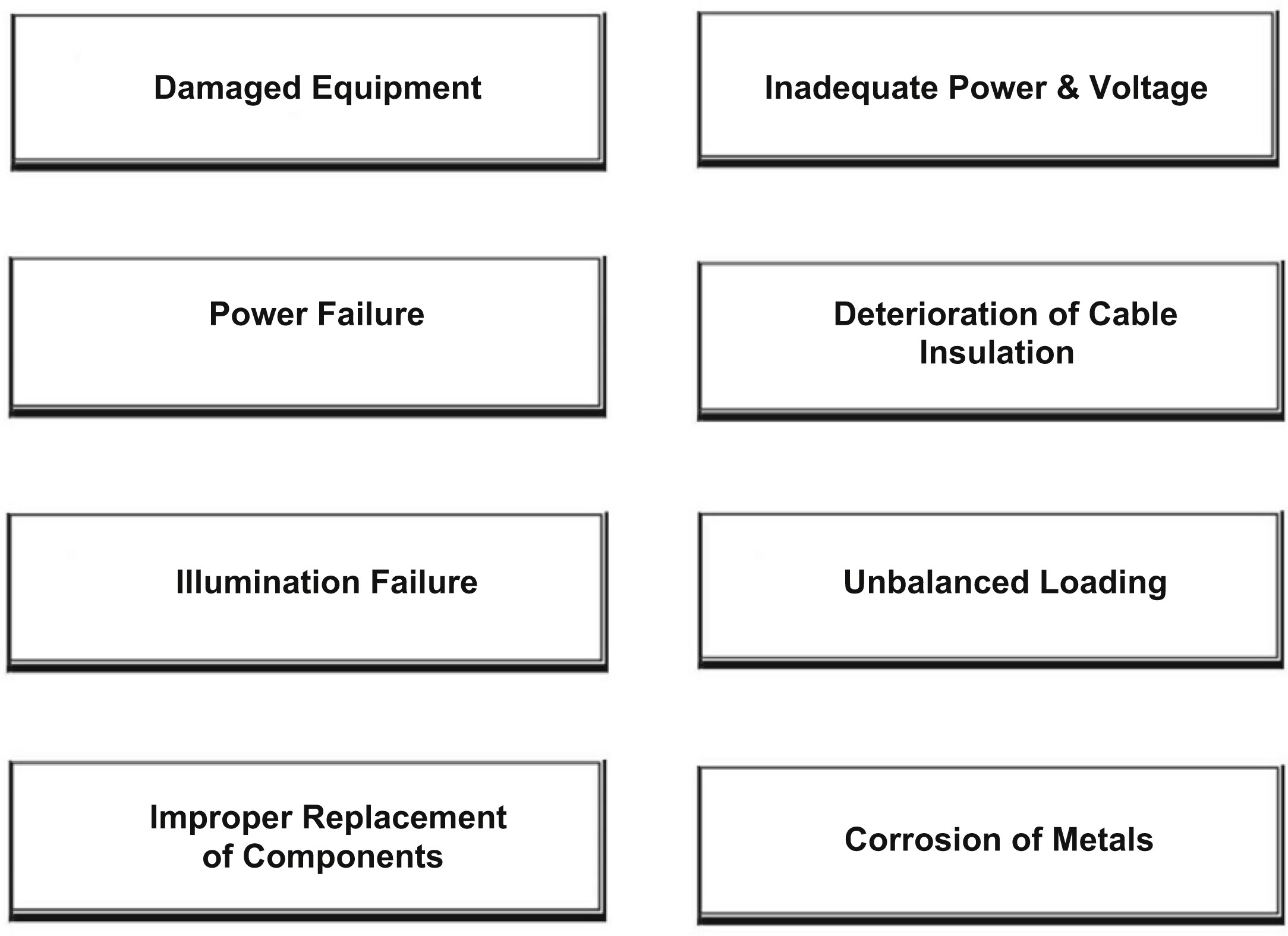
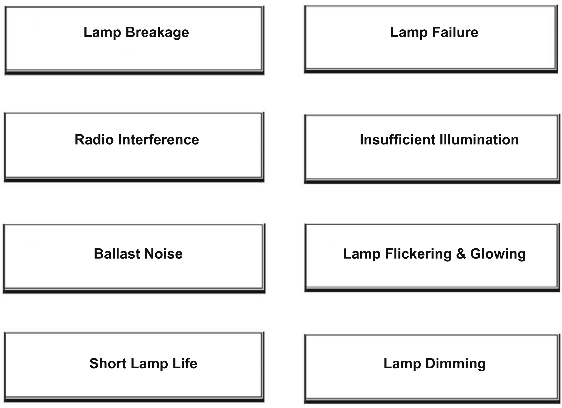
The difference between commercial and residential electrical installations can be quite significant, particularly with large installations. While the electrical needs of a commercial building can be simple, consisting of a few lights for some small structures, they are often quite complex, with transformers and heavy industrial equipment. When electrical or lighting system deficiencies become evident and need attention, they are usually measurable and include power surges, tripped CBs, noisy ballasts, and other more obvious conditions such as inoperative electrical receptacles or lighting fixtures that are frequently discovered or observed during a review of the system. As illustrated in Figs. 9.21 and 9.22, there are a number of typical deficiencies found in both the electrical and the lighting systems.
In commercial buildings, the major load placed on a given electrical system usually comes from the lighting requirements; therefore, the distribution and management of electrical and lighting loads must always be monitored on a regular basis. Lighting management should also be periodically checked because building space uses change and users relocate within the building. It is also highly advisable for the lighting system to be integrated with the electrical system in the facility. Lighting systems are designed to ensure adequate visibility for both the interior and exterior of a facility and are comprised of an energy source, and distribution elements normally consisting of wiring, and light-emitting equipment.
There are several different electrical codes today being enforced in various jurisdictions throughout the United States. Some of the larger cities, such as New York and Los Angeles, have created and adopted their own electrical codes. The National Electrical Code (NEC) and the National Fire Protection Code (NFPC), published by the National Fire Protection Association (NFPA), cover almost all electrical system components. The NEC is commonly adopted in whole or in part by municipalities. Inspection of the electrical and lighting system should include a determination of general compliance with these codes at the facility. With very large facilities employing complex electrical equipment, it may be necessary to operate it under engineering supervision or alternatively to have a full-time facilities manager.
9.5.1. Understanding Amps, Volts, and Watts
The electrical service in most countries around the world is brought into a building at either 240V or 120V. These numbers are called “nominal,” meaning that the actual voltage may vary. Most modern buildings receive 240V service, a total achieved by the provision of two individual 120V incoming power lines. Older buildings and electrical services often delivered only 120V. While knowing the available voltage level is important, this information alone is insufficient as it does not indicate the amount of electrical power available inside a building. In order to calculate this we need to know the service voltage at a building, in addition to the service amperage. However, before proceeding it would be prudent to have a basic understanding of some common electrical terms that apply to electrical systems.
Amperage (A or AMP)
This is a unit of electrical current. The Amperage or Amps provided by an electrical service is the flow rate of “electrical current” that is available. Appliances will typically have an Amp rating or if only a wattage is quoted, Amps = Wattage/Voltage. Practically speaking, the voltage level provided by an electrical service, combined with the ampacity rating of the service panel, determines the electrical load or capacity. Branch circuit wire sizes and fusing or CBs used to typically set the limit on the total electrical load or the number of electrical devices that can be run at once on a given circuit. Thus, for example, if you have a 100A current flow rate in place, you may be able to run approximately 10 amp electric heaters simultaneously. If you have only 60A available, you will not be able to run more than six such heaters without risking overheating the wiring, tripping a CB, blowing a fuse or causing a fire, which is why it is important to avoid overloading the system.
To be able to determine the amount of electrical service a facility receives the service ampacity and voltage must be known. The safe and proper service amperage available at a property is set by the smallest of the service conductors, the main disconnect fuse or switch, or the rated capacity of the electric panel itself. The main fuse/CB is the only component, which actively limits amperage at a property by shutting off loads drawing more than the main fuse rating. The main breakers or fuses are allowed to have lower overcurrent protection than the capability of the service equipment (panel) and conductors (entrance cable).
Voltage
A Volt (V) can be defined in several ways; often it is defined as the potential difference across a conductor when a current of 1A dissipates 1W of power. Practically speaking, a volt is a measure of the strength of an electrical source at a given current or amperage level. If we bring 100A into a building at 240V, we have twice as much power available as if we bring in 100A at 120V. However, if we exceed the current rating of a wire it will get hot, risking a fire. This is why fuse devices are employed to limit the current flow on electrical conductors to a safe level and thereby prevent overheating and potential fires. Moreover, as previously mentioned, a “240V” circuit is a nominal rating, which implies that the actual voltage level will vary. In many countries the actual voltage level varies around the nominal delivered “voltage rating” and in fact depending on the quality of electrical power delivered on a particular service, voltage will also vary continuously around its actual rating. Most electrical power systems are prone to slight variations in voltage due to demand or other factors. Generally, this difference is inconsequential, as most appliances are built to tolerate current a certain percentage above or below the rated voltage. However, severe variations in current can damage electrical equipment, which is why installing a voltage stabilizer is always advisable where sensitive electronic equipment is used.
Wattage
In electricity, a watt is a unit of measure of electric power and is equal to current (in amperes) multiplied by voltage (in volts). Most people use a very simple mathematical formula to determine how many watts an electrical circuit can carry or how many watts an electrical device will require: Watts = Volts × Amps. In buildings the unit of electricity consumption measure is the watt hour, which is usually in thousands, called kilowatt hours (kwh). In larger buildings, not only is the total consumption rate measured but also the peak demand as well.
9.5.2. Electrical Components
It is the electrical control system that is used to control a buildings HVAC system. As previously mentioned, modern Building Automated Systems (BAS) can also control indoor and outdoor lighting as well as security, fire alarms, and basically everything else that is electrical in the building. Still, even though electric service is vital to all residential and commercial buildings, it is nevertheless often one of the last components to be installed during the construction process.
Service Connections
Planning the design, construction, and timing of installation of electric service to a construction project should be contemplated from the very early stages. The service connection equipment basically provides a connection between the power company service and the facility and also measures the amount of electricity a facility uses. From here a meter either feeds a disconnect switch or a main breaker or fuse panel. The connection can be located either overhead or underground. The service connection should be checked for type (i.e., voltage, amperage), and general condition and whether the total power adequately serves the facility’s requirements. The equipment should be clean and free from overgrown planting and debris. A detailed discussion of installation requirements of electric service connections is outside our scope.
Switchgear and Switchboards
The function of switching equipment is to control the power supply in the facility and all the services arriving on the site (service drop). This consists of the wires from the main line, a transformer, a meter, and a disconnect switch. The main service switch is the system disconnect for the entire electrical service and is generally used in combination with metering, disconnect switch, protective, and regulating equipment to protect and control motors, generators, transformers, and transmission and distribution lines. The main service switch is the system disconnect for the entire electrical service. To avoid excessive voltage drop and flicker, the distance from the transformer to the meter should not exceed 150 ft. In commercial construction the panel and disconnect should preferably be located outside the building but may be located inside the building if they are accessible from an exterior door.
A switchboard is comprised of one or more panels with various switches and indicators that are used to route electricity and operate circuits. The main switchboard controls and protects the main feeder lines of the system. Switchgear and switchboards should be readily accessible, in good condition, and have protective panels and doors. They should also be checked for evidence of overloading or burn marks. Switchboard covers should not normally be removed.
Switchgears are typically concentrated at points where electrical systems make significant changes in power, current, or routing, such as electrical supply substations and control centers. Switchgear assemblies range in size from smaller, ground-mounted units to large walk-in installations and can be classified as outdoor or indoor units. Commercial and industrial assemblies are usually indoors, while utilities and cogeneration facilities are more likely to have outdoor gear. Manufactured for a variety of functions and power levels, all switchgear conforms to standards set by the Institute of Electrical and Electronic Engineers (IEEE), the National Electrical Manufacturers Association (NEMA), or the American National Standards Institute (ANSI).
Meters
There are basically two methods of measuring electric consumption in a building. In residential applications, only the total electric consumption is measured. In larger facilities, both the total consumption peak rate demands are measured. This is because large peaks require the utility company to build more power-generating capacity to meet the peak. Commercial services of up to 200 amps single phase may have service panels similar to those found in residences. Larger services may require stand-alone switchboards with one or more meters. In a multiple occupancy building, there may be separate meters for each tenant or common metering.
Panelboards
Electrical panelboards and their cabinets house an assembly of CBs and control and protect the branch circuits. From the panelboards the power generation can be monitored and the power generated can be distributed. In addition to control and protect the branch circuits, panelboards are designed to providing a central distributing point for the branch circuits for a building, a floor, or part of a floor. Each breaker serves a single circuit, and the overload protection is based on the size and current-carrying capacity of the wiring in that circuit. A building may have a number of panelboards and a main panel with a disconnect switch for the entire building. The following are examples of lighting panel types:
• Plug-in CBs (1-pole)
• Bolt-on CBs (1-pole, 2-pole, 3-pole)
• Fusible switch.
To estimate the electric service panel ampacity, Evidence of a tag (normally paper) or embossed rating on fuse pull outs on the panel itself and often includes the amperage rating of the panel. This information is usually present in newer panels on a panel side or on the panel cover. Actual dimensions of an electric panel are not a reliable determinant of ampacity. For example, many larger panels can be fitted with a variety of bus bar and main switch assemblies of varying ampacity.
Aluminum Wiring
During the 1970s, aluminum (instead of copper) wiring became quite popular and used extensively. Since that time however, aluminum-wired connections have been implicated in a number of house fires, and most jurisdictions no longer permit their use in new installations (http://www.inspect-ny.com/aluminum/ja-54.jpg). Aluminum-wired connections have been found to have a very high probability of overheating compared with copper-wired connections and were therefore a potential fire hazard. Over the years, a large number of connection burnouts have occurred in aluminum-wired homes, and according to the U.S. Consumer Product Safety Commission, many fires have resulted, some involving injury and death. The main problem with aluminum wiring is a phenomenon known as “cold creep.” When aluminum wiring warms up, it expands, and when it cools down, it contracts. However, unlike copper, when aluminum goes through a number of warm/cool cycles it begins to lose some of its tightness. To add to the problem, aluminum oxidizes, or corrodes when in contact with certain types of metal, so the resistance of the connection increases. This causes it to heat up and corrode/oxidize still more and until eventually the wire may start getting very hot and melt the insulation or fixture it is attached to, and possibly even cause a fire without ever tripping the CB.
Although aluminum wire “alloys” were introduced in the early 1970s, this did not adequately address most of the connection failure problems. Aluminum wiring is still permitted and used for certain applications, including residential service entrance wiring and single-purpose higher amperage circuits such as 240V air conditioning or electric range circuits. Although the fire risk from single purpose circuits is much less than for branch circuits, field reports indicate that these connections remain a potential fire hazard.
A simple method of identifying aluminum wiring is to examine the wire sheathing for the word aluminum. If you cannot find the word aluminum embossed in the wire sheathing, then look for silver-colored wire instead of the copper-colored wire used in modern wiring. Without opening any electrical panels or other devices, it is possible to still look for printed or embossed letters on the plastic wire jacket where wiring is visible at the electric panel. Some aluminum wire has the word “Aluminum” or a specific brand name such as “Kaiser,” “Alcan,” “Aluminum,” or “AL/2” plainly marked on the plastic wire jacket. Some white-colored plastic wire jackets are inked in red; others have embossed letters without ink and are hard to read. Shining a light along the wire may make it easier to identify. Of note, the fact that no aluminum wiring was evident in the panel does not necessarily mean that none is present. Aluminum may have been used for part of circuits or for some but not other circuits in the building.
Service Outlets and Receptacles
Service outlets include convenience receptacles, motors, lights, and appliances. Receptacles are commonly known as outlets or sometimes erroneously as wall plugs (a plug is what actually goes into the outlet). It is preferable for outlets to be three-prong where the third prong is grounded. For large spaces or areas, all of the outlets should not be on the same circuit so that when a fuse or CB trips due to an overload, the space will not be plunged into complete darkness. Important specifications for electrical receptacles include number of poles and grounding method. Today’s electrical receptacles have a variety of features. Some devices include surge protection against mild to moderate spikes or peaks in the electrical supply, while others have a locking mechanism or a power light.
Grounding
The grounding of a service to earth is basically a safety precaution and is necessary mainly to protect against lightning strikes or other high-voltage line strikes. It is important to conform to the National Electric Code (NEC) when considering grounding. The NEC is the benchmark for safe electrical design, installation, and inspection to protect people and property from electrical hazards. Official document scope is Adopted in all 50 states. The NEC addresses the installation of electrical conductors, equipment, and raceways; signaling and communications conductors, equipment, and raceways; and optical fiber cables and raceways in commercial, residential, and industrial occupancies.
Earth grounding in a commercial building might be to a grounding rod inside a switchboard, to a steel cold water pipe in the plumbing system, or to the steel frame of a building. Other methods of grounding are also used depending on the equipment or system to be grounded. Grounding also drains the static charges away as quickly as they are produced. Ground wires are typically covered with green insulation or sometimes may be without cover.
Motors, Switches, and Controls
These are devices that convert any form of energy into mechanical energy, especially an internal combustion engine or an arrangement of coils and magnets that converts electric current into mechanical power. Basically, there are four types of motors in general use, they are as follows:
• Stepper/Switched Reluctance (SR) Motors are brushless, synchronous electric motors that can divide a full rotation into a large number of steps. The motor’s position can be controlled precisely, without any feedback mechanism. Stepper motors are basically similar to SR Motors—in fact the latter are very large stepping motors with a reduced pole count and generally are closed-loop commutated. The main advantage of stepper motors is that they can achieve accurate position control without the requirement for position feedback. Stepper motors operate differently from normal DC motors, which rotate when voltage is applied to their terminals.
• The most common and simple industrial motor is the three-phase AC Induction Motor. This type can be either three-phase AC or single-phase AC. The three-phase AC induction motor is a rotating electric machine designed to operate from a three-phase source of alternating voltage and usually applies to larger motors. These motors are characterized by extreme reliability and remain constant in rpm, unless heavily overloaded. The single-phase motor is a rotating machine that has both main and auxiliary windings and a squirrel cage rotor.
• The fourth type of motor in general use is the Universal Motor, which is a rotating electric machine similar to a DC motor but designed to operate either from direct current or single-phase alternating current, and which varies in speed based on the load. The universal motor is usually found in mixers, hand drills, and similar appliances. Motors should always be protected against overload by thermal relays, which shut off the power when any part of the motor or housing overheats.
Switches and Controls
Switches and controls are devices that direct the flow of power service to the electrical equipment. Safety switches are installed in locations where service cutoff is available in case of emergencies. These include toggle switches, dials, and levers. The quality of control switches is based on the gold or silver plating, which determines life cycles. Today, most vendors now also offer customized rotary switches based on the specific needs of end users.
Emergency Power
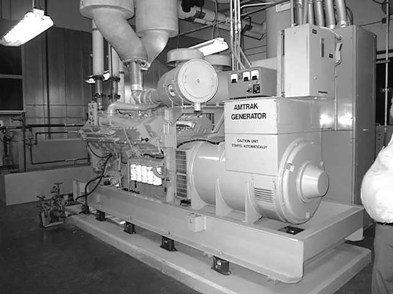
For certain facilities, it is an absolute necessity to have standby power with which to ensure continued electrical service when a shutdown of the standard power service takes place. Emergency power is required for life support systems, fire and life safety circuits, elevators, exit, and emergency lighting. Facilities which require full operation during emergencies or disasters, such as hospitals and shelters, always have backup power. Computer facilities, to ensure continued storage and survival of the data, also commonly have emergency power. For major equipment, a diesel engine generator with an automatic starting switch and an automatic transfer switch is often provided for emergency power (Fig. 9.23) while for lighting, battery units are installed. The typical AC power frequency in the United States is 60 cycles per second or 60 Hz, whereas in Europe, 50 Hz is the standard.
However, for emergency power to function properly, it is imperative to ensure that the interconnected systems are also functioning. This includes but not limited to ancillary equipment such as starters, fuel and lubrication pumps, and cooling equipment. Likewise, distribution systems such as switchgear, panels, controllers, branch circuits, feeders, transfer switches, transformers, and so forth also need to function. Failure of any component in the emergency power system can prevent its proper operation. In regions where there is the possibility of earthquakes, all components of the system must be designed and braced for seismic loads.
Transformers
The US Department of Energy has recently mandated that effective January 1, 2016; distribution transformers manufactured for the United States must meet the new, more stringent Energy Efficiency Standard (DOE, 2016) as part of the Energy Policy and Conservation Act (EPCA). Understanding the new standard and its impact will help ensure a seamless transition to compliant transformer designs. Transformers are devices that convert an alternating current (A/C) circuit of a certain voltage to a higher or lower value, without change of frequency, by electromagnetic induction. Transformers are used to step up voltage (called “step up” transformers) in order to transmit power over long distances without excessive losses and subsequently step down voltage (called “step down” transformers) to more useable levels. While a transformer changes the voltage of an alternating current (AC) in a circuit to a higher or lower value, it has practically no effect on the total power in the circuit.
The DOE defines a Distribution Transformer as:
• Having input voltage of 34.5 kV or less
• Having an output voltage of 600 V or less
• Being rated for operation at a frequency of 60 Hz
• Featuring a capacity range for dry-type transformers of 15–2500 kVA
• Being either a single- or three-phase transformer.
The full standard can be found in the Code of Federal Regulations.
Transformers come in two distinct types: They can be wet or dry type. There are also subcategories of each main type. Lower voltage types are dry, and typically noise generating, with minimal requirements for insulation and avenues for ventilation of heat generated by voltage changes. For wet or liquid-filled transformers, the cooling medium can be conventional mineral oil. Some wet-type transformers use less flammable liquids, such as high fire point hydrocarbons and silicones. Wet transformers are typically more efficient than dry types and usually have a longer life expectancy. There are some drawbacks, however. For example, fire prevention is more important with liquid-type units because the liquid cooling medium used may catch fire (although dry-type transformers are also susceptible) or even explode. Wet-type transformers typically contain a type of fire-resistive fluid or mineral oil such as PCBs, and, depending on the application, wet transformers may require a containment trough for protection against possible leaks of the fluid, which is why they are preferred predominantly when placed outdoors.
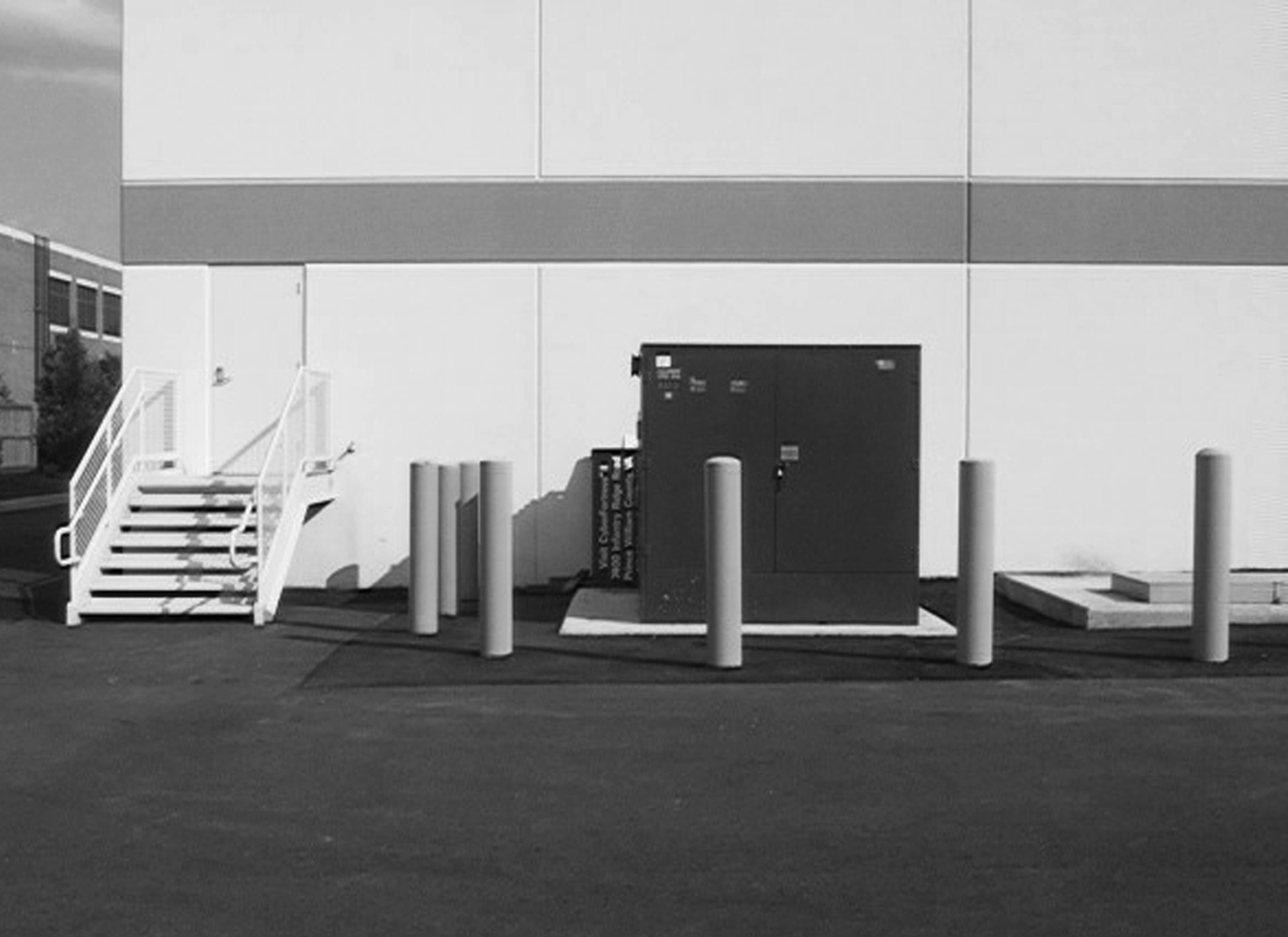
For lower voltage type indoor-installed distribution transformers of 600V and below the dry-type transformer is preferred even though they have minimal requirements for insulation and avenues for ventilation of heat generated by voltage changes. Dry-type transformers come in enclosures that have louvers or are sealed. Location of transformers should be carefully considered and there should be clear access surrounding exterior transformers and adequate ventilation and access for interior transformers, which should be inside a fireproof vault. On-site transformers in parking lots may require bollards or other protection (Fig. 9.24). Transformers should be analyzed for PCB’s and their registration number noted. In addition, transformers tend to make a certain amount of noise (hum), which should be addressed if it causes irritation.
9.5.3. Lighting Systems
The main function of good lighting, whether natural or artificial, is to provide visibility and allow us to see so that we can perform our tasks, and thus making a space useable. Different artificial sources produce different kinds of light, and vary significantly in their efficiency, which is the calculated lumen output per watt input. Another primary objective must be to minimize energy usage while achieving the visibility, quality, and aesthetic objectives. The quality and quantity of lighting affect the ambience, security, and function of a facility as well as the performance of its employees. Divergent artificial sources produce different kinds of light, and vary significantly in their efficiency, which is the calculated lumen output per watt input. Regrettably, US lighting design does not readily translate overseas—not when different regions have their own voltage, product standards, construction methods, and conceptions about what light is meant to achieve. However, this is facilitated by increased integration of the lighting systems which simplifies electrical distribution and control systems design. In fact, energy efficiency is the main theme of the recent (March 2016—Frankfurt, Germany) Light + Building exhibition which is held every 2 years is energy efficiency. Light + Building is the platform when it comes to the latest innovations around lighting and building automation. It is the world’s leading trade fair for architecture and technology; the exhibition period is firmly rooted in the calendars of the visitors and exhibitors (210,000 visitors and 2400 exhibitors) to see innovations and trends. Moreover, the popularity of the exhibition is clearly reflected by the number of visitors and exhibitors.
Interior Lighting
Because lighting typically accounts for a significant percentage of the annual commercial business and residential electric bills, it is important to understand the relationship between a source of light, the surfaces that reflect light, and how we see light, and the need to have a common comprehensive lighting language. It goes without saying that without a light source we cannot see, and without surfaces to reflect light, there is nothing to see. Advances in lighting technology can make significant reductions in the amount of money that is spent for lighting a facility. More important, interior lighting should meet minimum illumination levels (Table 9.3). It is important to determine the amount of light required for the activity that will take place in a space. Typically, the illuminance levels needed for visibility and perception increases with high accuracy activities and as the size of details decreases, as contrast between details and their backgrounds is reduced, and as task reflectance is reduced. However, interior lighting must not exceed allowed power limits. Interior lighting includes all permanently installed general and task lighting shown on the plans but does not include specialized lighting for medical, dental, or research purposes and display lighting for exhibits in galleries, monuments, and museums. For this reason, there are many types of interior lighting systems that address these needs and enable us to make full use of a facility around the clock. The most common categories are as follows:
Table 9.3
Table of recommended illumination levels for various functions
| Area | Foot-candles |
| Building surrounds | 1 |
| Parking area | 5 |
| Exterior entrance | 5 |
| Exterior shipping area | 20 |
| Exterior loading platforms | 20 |
| Office corridors and stairways | 20 |
| Elevators and escalators | 20 |
| Reception rooms | 30 |
| Reading or writing areas | 70 |
| General office work areas | 100 |
| Accounting/bookkeeping areas | 150 |
| Detailed drafting areas | 200 |
• Fluorescent Lamps: This type of fixture has long been preferable to incandescent lighting, in terms of energy efficiency. Fluorescent lighting is far more efficient than incandescent bulbs and has an average life of 10–20 times longer (fluorescent lamps last up to 20,000 h of use), and use roughly one-third as much electricity as incandescent bulbs with comparable output. Compact fluorescent lamps (CFLs) are similar in operation to standard fluorescent lamps but are manufactured to produce colors similar to incandescent lamps. New developments with fluorescent technology, including the high-efficacy T-5, T-8, and T-10 lamps, have pushed the energy efficiency envelope further. Recently, attention has also been paid to the mercury content of fluorescents and the consequences of mercury release into the environment. As with all resource use and pollution issues, reduction is the best way to limit the problem. Even with low-mercury lamps, however, recycling of old lamps remains a high priority.
A fluorescent fixture typically consists of the lamp and associated ballast, which controls the voltage and the current to the lamp. Replacing standard incandescent light bulbs with CFLs will reportedly slash electrical consumption in homes and offices where incandescent lighting is widely used. By reducing the amount of electricity used, corresponding emissions of associated carbon dioxide, sulfur dioxide, and nitrous oxide are reduced. CFL technology continues to develop and evolve and is now capable of replacing most of the light fixtures that were originally designed for incandescent light bulbs.
Francis Rubinstein, a scientist and energy-efficiency lighting expert at LBNL’s Environmental Energy Technologies Division, believes that fluorescent lighting will continue to dominate the general lighting market and that, in the near-term future, solid-state LED and fluorescent lighting will coexist in hybrid systems—in combination with advanced lighting controls, achieving vast improvements in light efficiency.
• Incandescent Lamps: Incandescent lamps have relatively short lives (typically 1000–2000 h of use) and are the least efficient of common light sources. In fact, only about 15% of the energy they use comes out as light and the rest becomes heat. Nevertheless, remain popular because they produce a pleasant color that is similar to natural sunlight and they are the least expensive to buy. Incandescent lamps come in various shapes and sizes with different characteristics. The most common incandescent outdoor lighting options are metal halide and high-pressure sodium (HPS). Environmental issues include lamp efficacy (lumens per watt), luminaire efficiency, controllability of the light source, potential for PV power, and control of light pollution. To control light pollution, full cutoff luminaires should be specified. It also makes very good sense to use whenever possible environmentally friendly, commercial outdoor lighting systems. For example, Energy Star lights consume only about 20% of the energy consumed by traditional lighting products, thus providing substantial savings in money spent, energy consumed, and greenhouse gas emissions reduction.
Tungsten halogen lamps are a type of incandescent lamp that has become increasingly popular in recent years. They produce a whiter, more intense light than standard incandescent lamps and are typically used for decorative, display or accent lighting. They are about twice as efficient as regular incandescent lamps and last two to four times longer than a typical incandescent lamp.
• High-Intensity Discharge (HID): Wikipedia defines HID lamps as “a type of electrical gas-discharge lamp which produces light by means of an electric arc between tungsten electrodes housed inside a translucent or transparent fused quartz or fused alumina arc tube.” This category of high-output light source consists of a lamp within a lamp that runs at a very high voltage. There are basically four types of HID lamps: (1) HPS lamp, (2) Mercury vapor lamps, (3) Metal halide gas, (4) Low-pressure sodium lamps. HID lights require ballasts for proper lamp operation (similar to fluorescent lights). The efficiency of HID sources varies widely from mercury vapor, with a low efficiency—almost as low as incandescent, to low-pressure sodium which is an extremely efficient light source. Color rendering also varies widely from the bluish cast of mercury vapor lamps to the distinctly yellow light of low-pressure sodium.
• Fiber Optics: This is an up and coming technology, providing an alternative that is superior to conventional interior and exterior lighting systems. The technology possesses enormous information-carrying capacity, is low cost, and is immune from many of the disturbances that often afflict electrical wires and wireless communication systems. Fiber optics first emerged in the United States during the 1980s as a way to transmit data far more effectively than other communication systems. Since then researchers have been able to radically improve the efficiency by conveying several data streams over one cable using diverse frequencies.
Fiber optics technology is based on the use of hair-thin, transparent fibers to transmit light or infrared signals. The fibers are flexible and consist of a core of optically transparent glass or plastic, surrounded by a glass or plastic cladding that reflects the light signals back into the core. Light signals can be modulated to carry almost any other sort of signal, including sounds, electrical signals, and computer data, and a single fiber can carry hundreds of such signals simultaneously, literally at the speed of light. The superiority of optical fibers for carrying information from one location to another is leading to their rapidly replacing many older technologies. A typical fiber optic lighting system can be broken down into two basic components: a light source, which generates the light, and the fiber optics, which will deliver the light.
Although fiber optic lighting offers unique flexibility compared to conventional lighting, it does have its limitations. Areas of high ambient light should be avoided as they tend to “wash out” the color. However, often fiber optics can be installed in areas not accessible to conventional lighting. Good ventilation is very necessary for all illuminators. Light-colored reflective surfaces are preferable for end light or sidelight applications. Dark surfaces absorb light and should only be used to provide contrast. Typical applications include cove lighting, walkway lighting, and entertainment illumination (Fig. 9.25). One cannot overemphasize the crucial role that optical fibers played and continue to play in making possible the extraordinary growth in worldwide communications that has occurred over the last 2–3 decades, and which is vital in enabling the proliferating use of the Internet and the creation of the “Information Age.” In fact fiber optics systems were even used aboard the NASA space shuttle Endeavor during its February 2000 mission.
It is a well-known fact that all electric light sources experience lumen depreciation and thus the useful life of a lighting installation becomes progressively less efficient during its operation due to dirt accumulation on the surface and aging of the equipment. The rate of reduction is influenced by the equipment choice and the environmental and operating conditions. In lighting scheme design we must take account of this deficiency by the use of a maintenance factor and plan suitable maintenance schedules to limit the decay.
Exterior Lighting Systems
It is generally necessary to have adequate outdoor lighting around buildings and there are many innovative, energy-efficient lighting solutions for outdoor applications. The adequacy of outdoor lighting is an important factor in maintaining good security in parking lots and other outdoor areas. The inadequacy of exterior lighting has been the basis of many lawsuits alleging that the facility owner was negligent in providing a proper level of security. In older buildings it is likely that the outdoor security lighting is inadequate, largely because for many years, lighting in parking lots and other outdoor areas was a low priority for lighting designers. Exterior lighting should be carefully designed and sufficient thought given to its placement, intensity, timing, duration, and color and should meet the requirements of The Illuminating Engineering Society of North America (IES or IESNA). Outdoor lighting used to illuminate statues, signs, flags, or other objects mounted on a pole, pedestal or platform, spotlighting or floodlighting used for architectural or landscape purposes, must use full cutoff or directionally shielded lighting fixtures that are aimed and controlled so that the directed light is substantially confined to the object intended to be illuminated. Facility evaluations are often required to identify inadequate exterior lighting conditions. Lighting controls are necessary to ensure that exterior light is available only when required. Full cutoff lighting fixtures are required for all outdoor walkway, parking lot, canopy and building/wall-mounted lighting, and all lighting fixtures located within those portions of open-sided parking structures that are above ground. An open-sided parking structure is a parking structure which contains exterior walls that are not fully enclosed between the floor and ceiling.
Many cities and towns around the country have enacted ordinances concerning “light pollution.” These ordinances often set limits on the amount and type of light that can be used for outdoor parking lot lighting. It is important to consult local jurisdiction before making any changes in the lighting system. Moreover, to meet code requirements, automatic controls are typically required for all exterior lights. The control may be a directional photocell, an astronomical time switch, or a BAS with astronomical time switch capabilities. The control should automatically turn off exterior lighting when daylight is available. Lights in parking garages, tunnels, and other large covered areas that are required to be on during daylight hours are exempt from this requirement. Incandescent and HID is the most common type for exterior lighting. Illumination levels should be adequate and in good condition. The growth of trees and other types of landscaping provides another challenge that may have to be addressed. It can have a significant impact on outdoor lighting. Often, a well-designed lighting system becomes ineffective due to tree grow to a point where large portions of the light are blocked out. This can be addressed by arranging to have trees and landscaping regularly trimmed so that the lighting system is not adversely affected.
Emergency Lighting Systems
Emergency power systems are intended to serve three primary functions:
• Provide a safe environment for building occupants in the event of a power loss.
• Protect equipment and property from damage.
• Provide continuity of operations.
In the event of an emergency, where an electric failure occurs, it can cut power to a main lighting system. Emergency lighting systems are arranged to provide continuity of this very essential service, and which are comprised of lighting fixtures connected to the 110-V power source.
NFPA 101 2006 stipulates that Emergency illumination (when required) must be provided for a minimum period of 1.5 h to compensate for the possible failure of normal lighting. NFPA also requires emergency lighting to be arranged to provide initial illumination of not less than an average of one foot-candle and a minimum at any point of 0.1 foot-candle measured along the path of egress at floor level. In all cases an emergency lighting system must be designed to provide illumination automatically in the event of any interruption of normal lighting (NFPA 101 2006 7.9.2.3). Emergency lighting and LED signs typically use relatively small amounts of energy and have a long life expectancy. Although LED fixtures may cost more than incandescent fixtures, reduced energy costs and labor savings will often quickly make up the difference.
For most facilities, having an emergency lighting system in place is necessary in the event of a power failure or other emergency; emergency lighting in a facility enables the occupants to exit safely. Emergency lighting can consist of individual battery units placed in all corridors, stairwells, lobbies, and key locations that may require sufficient lighting for building user exiting, in interior and some exterior exitways. These batteries are continuously recharged while power is on, and which take over when power is lost. Also, the advantages of this type of emergency lighting system are flexibility; technicians can relocate the systems effortlessly to accommodate any changes in the building’s layout. Since each lamp has its own power source, if one goes out, the others will remain in operation. Alternatively, the lighting can be powered by a central battery unit. Fluorescent lamps will require some method of power conversion as batteries are typically 12 volt.
9.5.4. Harmonics
Loads connected to electricity supply systems may be broadly categorized as either linear or nonlinear. There was a time when almost all electrical loads were linear—those that were not made up such a small portion of the total that they had little effect on electrical system operation. That all changed, however, with the arrival of the solid-state electronic revolution. Today, we are immersed in an environment rich in nonlinear loads, including:
• A variety of solid state devices, such as desktop computers,
• UPS equipment,
• Industrial equipment (welding machines, arc furnaces, induction furnaces, rectifiers)
• Office equipment (PCs, photocopy machines, fax machines, and so forth)
• Inverters
• Variable speed drives for asynchronous and DC motors
• Induction motors
• Household appliances (television sets, microwave ovens, fluorescent lighting, and so forth).
Operation of these devices represents a double-edged sword. While they provide greater efficiency, they can also cause serious consequences to power distribution systems—by creating high levels of harmonic distortion. In reality, total harmonic distortion is hardly perceptible to the human ear, and even though the voltage distortion caused by the increasing penetration of nonlinear loads is often accommodated without serious consequences, power quality is compromised in other cases unless steps are taken to address this phenomenon.
Although most of the loads connected to the electricity supply system draw power that is a linear (or near linear) function of the voltage and current supplied to it, these linear loads do not normally cause disturbance or adversely impact other users of the supply system. Some types of loads however cause a distortion of the supply voltage/current waveform due to their nonlinear impedance. Harmonic distortion can surface in electric supply systems through the presence of nonlinear loads of sufficient size and quantity. The severity of problems depends upon the local and regional supply characteristics, the size of the loads, the quantity of these loads, and how the loads interact with each other. Utility companies are clearly concerned about emerging problems caused by increasing concentrations of nonlinear loads resulting from the growing proliferation of electronic equipment, particularly computers and their AC to DC power supply converters, and electronic controllers. By taking a closer look at linear and nonlinear loads, we can get a better understanding of the hows and whys of this distortion.
Harmonic Reduction
Reducing harmonic voltage and current distortion from nonlinear distribution loads such as adjustable frequency drives (AFDs) can be achieved through use of several basic approaches. However, in the presence of excessive harmonic distortion, it is highly recommended to bring in a specialized consultant to correct the issue. Some of the methods used by harmonic specialists to reduce harmonic distortion may include the use of a DC choke, line reactors, 12-pulse converters, 12-pulse distribution, harmonic trap filters, broadband filters, and active filters. Whatever approach is applied to achieve reduction, it must meet the guidelines of the IEEE. Furthermore, control of lower order powerline harmonic emissions from nonlinear loads is rapidly becoming one of the most severe and complex electrical challenges facing the electrical industry, and one that requires close cooperation between utilities, equipment manufacturers, premises owners, and end users if it is to be addressed.
..................Content has been hidden....................
You can't read the all page of ebook, please click here login for view all page.