
This is probably one of the most missed items when it comes to home studios. I am constantly bombarded by people coming to ask how they can fix their room. The work’s all done, it’s airtight, beautiful, sounds great, and they suddenly realize that they need fresh air, air conditioning, heat, the usual amenities.
I shake my head in wonder as I think about how many people miss this so very basic requirement. Re-work is always a lot more expensive than doing it right the first time. So save your money, keep your sanity, and plan for this now.
Again, remember, this chapter isn’t going to teach you how to install these systems. It won’t tell you how to sweat a copper joint or how to braze compression lines for coolants. It will give you the knowledge of the design concepts with enough depth to discuss your needs with professionals intelligently. Beyond this, you need professionals for the final design and installation on HVAC systems. There are too many different factors that come into play with HVAC systems to cover them all in this book. Heck, you could fill an entire book by itself just going over the basics in design, but if you did that, you wouldn’t ever get to the part about building your studio.
First and foremost, understand that you have a super-insulated structure to deal with. All of this work that you’re going to do to keep sound in (and out) also helps tremendously to reduce thermal transmissions through the structure. Thus, the design cannot be based on the same criteria as your home.
Next, if you have separate control and sound rooms, then you have two very different requirements for these. The control room (for example) will typically be smaller in volume than your sound room, but will generally have more gear producing heat that needs to be dealt with. The sound room (on the other hand) will usually have greater heat and moisture from the human body than the control room, and this too needs to be dealt with.
So it isn’t as simple as it might appear. Let’s begin with your control room.
The beginning of this is an assessment (on your part) as to the equipment you have (and will have) within this space. Yep, you have to reasonably anticipate what’s coming in the future. The reason for this is that all of this equipment gives off heat when it’s working, and you need to deal with that heat. Once you have this figured out, make up a list and include, as a part of that list, what the total wattage is for each and every piece of gear.
If you are going to install an isolation transformer in a location that will transfer heat into the room, you should include this in your calculations. Again, provide the total wattage for the unit. The same would go for a computer, UPS, and so on.
Lighting adds quite a bit of load to room cooling requirements, so a simple calculation based on the area of the room should be enough to cover this, unless you have some plans for very heavy lighting loads.
Next, you have to decide just how many people are going to be inside that room besides yourself. Once again, wattage is the data required for design. Yes, the heat that people give off can be calculated as wattage, you’ll learn how it’s done.
Finally, fresh air is taken into account.
All of this information is critical to proper HVAC design.
Let’s take a look at how this info is utilized.
One Btu (British thermal unit) is the amount of heat required to increase the temperature of one pound (one pint) of water by one degree F. This is roughly equal to the heat produced by one standard wooden match.
Thus, to bring one pound of water from freezing (32°F) to the state of boiling (212°F) requires 180Btu (i.e., 212°F- 32°F = 180°F = 180Btu).
To convert wattage into Btu output, you multiply watts times 3.4129. To convert Btu’s to watts, simply multiply times 0.2930711.
Calculating what people contribute to a room gets a little more involved.
To accurately calculate the Btu output of a person, you first have to determine their BSA (Body Surface Area). To determine this, you could use one of several mathematical models available. I prefer the Mosteller[1] formula, but other popular methods exist. My reason for preferring this formula over the others only has to do with the ease of use this one presents. The calculations can be performed with a simple handheld calculator. The Mosteller formula is:
BSA (m2) = ( [Height(cm) x Weight(kg)]/ 3600 )* .5
A person 5′-10″ tall (177.8cm) weighing 180.78 pounds (82kg) would have a BSA of 2.02594m2
BSA (m2) = ( [177.8cm × 180.78kg]/ 3600 )* .5 = 2.02594m2
To convert meters2 to feet2, simply multiply it times 10.7639104. So your friend above has a BSA of 21.807 feet2, and let’s call him Mr. “A.”
OK, now that you’ve dragged yourself through all of that, where do you go from here?
Well, if you look at Figure 7.1 you’ll see a set of values for the metabolic rate of people doing various tasks. The values are indicated as “met units.” One met unit equals the output of one square meter of skin.
Table 7.1. Metabolic rate chart.
Activity | Metabolic Rate (met units) |
Reclining | 0.8 |
Seated, quietly | 1.0 |
Sedentary activity (office, dwelling, lab, school) | 1.2 |
Standing, relaxed | 1.2 |
Light activity, standing (shopping, lab, light industry") | 1.6 |
Medium activity, standing (shop assistant, domestic work, machine work) | 2.0 |
High activity (heavy machine work, garage work) | 3.0 |
One met = 58.2 W/m2 - 18.4 Btu/h ft2 | |
This value (for 1 met unit) is 58.2 watts per meter squared or 18.46Btu per hour per square foot (58.2 watts * 3.4129)/10.76 = 18.45Btu/h f2). In an office setting, you would multiply this times 1.2 for a total of 69.84 watts(22.14Btu/h f2 ).
So, using the example above, Mr. “A” will produce (in a typical office setting) 482.81Btu/h or 141.48 watts/h (22.14Btu/h x 21.807 feet2). You’re going to use the data from Mr. “A” to represent the “typical adult” throughout these exercises.
Let’s create a 16x20 control room and fill it with the following equipment:
One 24-Channel Mixing Board with a 250 W power supply
One Stereo Vacuum Tube Power Amplifier, 500 W
Two Dual-Channel Tube Mic Preamps, 35 W each
Four 4-Channel Stereo Compressor Limiters, 35 W each
One Stereo Tube Limiter and Mic Preamp, 75 W
Six Effect Units, 16 W each
One 6-Channel Headphone System, 210 W
One 24-Channel Digital Recorder, 50 W
One 2-Track ¼″x7″ Stereo Reel to Reel, 30 W
That’s 1,493 watts of gear in a 320s.f. room that will hold a maximum of five people during mix-down. You decided you want clean power, so you’re using a 500-watt isolation transformer that will sit beside your desk.
If you’re building a studio with any serious sound-isolating capabilities, then you don’t have to bother taking passive solar gain into consideration, nor is thermal loss of any real consequence. There is, however, one other item to deal with, fresh air, which we will examine in a little bit.
Table 7.1 is a simple worksheet to calculate the heat-load within the room. If you put this all together and use the formulas in the table, you’ll see that the total Btu’s per hour of generated heat are 11,639.7.
Table 7.1. Heat-Load Calculation Chart A
Item | Required Input | Calculation | Heat Output |
|---|---|---|---|
Gear | Full Power Load in Watts | Total Wattage Load | 1493.0 WATTS |
Lighting | Room Area in Square Feet | Floor Area x 2.0 | 640.0 WATTS |
Power Distribution | Power System Rating in Watts | (0.02 x The Power System Rating) + (0.02 x Gear Above) | 22.8 WATTS |
People | Maximum Occupancy Load | 160.94 x each person | 804.7 WATTS |
Total | Total From Above | 3410.5 WATTS | |
Conversion | Multiply Wattage Total x 3.4129 | 11,639.7 Btu’s/Hr. |
It takes 12,000Btu’s to create one ton of cooling, so your needs are .97 tons of cooling per hour for the control room.
Now let’s add a tracking room to the equation. It’s going to be 15x21.5.
Let’s start again with a gear list:
In a tracking room, everything stays pretty much the same (from a calculation point of view) with the exception of the latent load per person. Musicians can generate as much Btu output as anyone who’s working fairly hard, so we will use a met rate of 3.0 for this space (353.56 W per person). Also (in this case), you won’t be using an isolation transformer for the space. Let’s calculate using a four-piece band working in this room.
If you create another worksheet (Table 7.2), you’ll see that the requirements in this room are different from the control room. Although the total load is only about ⅓ greater than the control room, the heat load due to people is fully double. The total load for this room is 1.08 tons.
Table 7.2. Heat-Load Calculation Chart B
Item | Required Input | Calculation | Heat Output |
|---|---|---|---|
Gear | Full Power Load in Watts | Total Wattage Load | 1550.0 WATTS |
Lighting | Room Area in Square Feet | Floor Area x 2.0 | 645.0 WATTS |
Power Distribution | Power System Rating in Watts | (0.02 x The Power System Rating) + (0.02 x Gear Above) | 0.0 WATTS |
People | Maximum Occupancy Load | 321.89 x each person | 1609.4 WATTS |
Total | Total From Above | 3804.4 WATTS | |
Conversion | Multiply Wattage Total x 3.4129 | 12,984.1 Btu’s/Hr. |
Remember that you still have to deal with fresh air and what it adds to the equation.
When you deal with cooling requirements, there are two very different loads you need to contend with. One of these you are familiar with, and the other you have probably never encountered.
Sensible loads are what you are used to seeing when you read a thermometer. You want it to be 70°F (21°C ), and it’s 85°F (29°C). So you need to cool down by 15°F (8°C). Simple right? Yes, it is, it’s the actual measurable change in temperature.
Latent loads (on the other hand) are a bit more involved. When dealing with latent loads, what you are actually doing is determining the amount of moisture that needs to be dehumidified, with the understanding that this will not change the temperature in the least.
Latent heat is defined as “heat that when added or removed, causes a change in state, but no change in temperature.”
For the purpose of air-conditioning design, the total Btu output from people is broken down further into sensible and latent loads. However, this is not linear. It isn’t a matter of 60/40% or any other fixed ratio. Just as the greater the activity, the greater the Btu output from your body, the greater percentage of that output is latent heat.
Take a minute and examine Table 7.3. It indicates how all of this goes together for a person. Note that on the right-hand side of the chart, the total output per person is broken down in Btu value as a percentage between sensible and latent output for the various activities we have been discussing.
Table 7.3. Heat-Load Breakdown per Activity
Activity | Met Rate | Wattage Output (m2) | Conversion to S.F. | Wattage Output (f2) | Btu Output | Watts Out Mr ″A″ | Conversion to Btu Output | Btu Out Mr. ″A″ | Sensible Heat% | Latent Heaf% | Sensible Btu/h | Latent Btu/h |
|---|---|---|---|---|---|---|---|---|---|---|---|---|
reclining | 0.8 | 46.56 | 10.7639104 | 4.33 | 14.76 | 94.2814 | 3.4129 | 322 | 60% | 40% | 192 | 130 |
seated quietly | 1 | 58.2 | 10.7639104 | 5.41 | 18.45 | 117.852 | 3.4129 | 402 | 66% | 34% | 267 | 135 |
sedentary activity | 1.2 | 69.84 | 10.7639104 | 6.49 | 22.14 | 141.422 | 3.4129 | 483 | 62% | 38% | 298 | 185 |
standing relaxed | 1.2 | 69.84 | 10.7639104 | 6.49 | 22.14 | 141.422 | 3.4129 | 483 | 62% | 38% | 298 | 185 |
light activity | 1.6 | 93.12 | 10.7639104 | 8.65 | 29.53 | 188.563 | 3.4129 | 644 | 52% | 48% | 334 | 310 |
meduim activity | 2 | 139.68 | 10.7639104 | 12.98 | 44.29 | 282.844 | 3.4129 | 965 | 31% | 69% | 295 | 670 |
high activity | 3 | 174.6 | 10.7639104 | 16.22 | 55.36 | 353.555 | 3.4129 | 1,207 | 30% | 70% | 357 | 850 |
A good rule of thumb for providing fresh air is 15cfm (cubic feet of air per minute) per person. So in keeping with our five people, 75cfm would be required for the control room and 60cfm for the sound room. This air is also going to have to be conditioned.
Accurately calculating the amount of humidity that fresh air adds to the “mix” here is no easy feat, but to help you understand the basics, I’ll pass on some information from ASHRAE (the American Society of Heating, Refrigerating, and Air-Conditioning Engineers).
In 1997, ASHRAE developed what they referred to as the “Ventilation Load Index” (VLI), which is the total load generated (in one year) by fresh air, calculated at the rate of 1cfm that is supplied to a building from the outside.
This index consists of two numbers, which separate the loads into dehumidification (latent) and cooling (sensible) loads for easy comparison. Thus it reads: latent ton-hours per cfm per year and sensible ton-hours per cfm per year.
Understanding the system is easy. For example, in Hartford, CT, the latent load is 3.0 ton-hours cfm per year and the sensible load is 0.3 ton-hours cfm per year. Based on your control room fresh air supply of 75cfm, that would translate to 225 tons (2,700,000Btu’s) of dehumidification required per year and 22.5 tons (270,000Btu’s) of cooling required per year.
Likewise, in Key West, Florida, it would be 21.6 + 3.5, indicating a need for 1,620 tons (19,440,000Btu’s) of dehumidification required per year and 262.5 tons (3,150,000Btu’s) of cooling required per year. One more example, and we’ll move on. In Reno, Nevada, it’s 0.0 + 0.8, thus 0 tons (0.0Btu’s) of dehumidification required per year and only 60 tons (9,600Btu’s) of cooling required per year.
The reason you have to pay attention to this is due to the fact that what fresh air adds to the room (unlike gear, people, and lights) is not a constant. As you can see, it can be anywhere from no real concern (Reno) to a huge concern (Key West), or anywhere in between (Hartford).
If you want to check what the index is for your area, you can download the ASHRAE document at the Web site of the Energy Resources Center, University of Illinois at Chicago. Search for “Dehumidification and Cooling Loads From Ventilation Air.” Understand one thing, this is not a factor you plug into your design calculation. It is simply a tool you can use to determine the extent of concern you should have with the design side of your system. The designers of the system will have to base their calculations on peak design loads.
Once again, looking at those ever-so-average adult human beings, they produce about 2.8kg of vapor per day, which is roughly 98.77oz. So our five people will produce about 14kg or almost 494oz. (3.86 gallons U.S.) of vapor per day.
That’s on top of whatever is brought in with the outside air, and all of this in a room that you want to maintain at a maximum of about 45% relative humidity.
In order to understand relative humidity, I want you to picture blowing up a balloon. You already know that you exhale vapor (among other things), so when you blow up that balloon, you will breathe a certain number of grains of vapor into it. The actual number is not important. After you blow the balloon up, look at it (in your mind’s eye, of course, after all, you are just picturing this, aren’t you?). It’s nice and plump because you did a good job of blowing it up. Now tie and seal the end.
Take the balloon and place it in your freezer. Let it sit there for a few hours. When you finally go look at it, you’ll find that it looks as if someone let some of the air out. They didn’t, but it still looks like it. However, the moisture within the balloon remains constant. The actual grains of vapor within the balloon did not change, but the amount of vapor relative to the volume of the air did change. If the balloon (in the state it was in when you blew it up) was 1c.f. of volume with 400 grains of vapor, and in the cold state was 1/10c.f. of volume, it would still contain the same 400 grains of vapor.
So the amount of vapor relative to the volume increases, hence the term “relative humidity.”
Picture now pulling 75cfm of fresh 95°F air with a relative humidity of 85% and placing it into your refrigerator of a room. The relative humidity is going to rise tremendously. You could literally end up with water running down your walls if it isn’t properly dehumidified. When air is 50% saturated, it contains only one-half the amount of water that it can contain at the same temperature and pressure. As the relative humidity approaches 100%, the air can take on less and less moisture, and at 100% relative humidity, that air cannot hold more water.
Relative humidity is determined by means of wet-bulb and dry-bulb thermometers. The dry-bulb temperature is the temperature of air as determined by a standard thermometer. The wet-bulb temperature is determined by tying a wet wick over the bulb dipped in a reservoir containing distilled water. Airflow around the wick causes the evaporation of moisture, thus lowering the temperature and producing a reading lower than that on the dry-bulb thermometer.
By taking the differences between these two readings and referring to a psychrometric chart, you can determine the relative humidity in a space. A psychrometric chart is nothing more than a graphical representation of several interrelated air parameters brought together. For a completely thorough explanation of the use of these charts, please visit the following Web site located at the University of Connecticut library (UCONN):
www.sp.uconn.edu/~mdarre/NE-127/NewFiles/psychrometric_inset.html
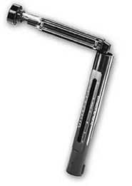
A sling psychrometer is a tool often used to do this. This is the most common type of hygrometer. Figure 7.2 is a sling psychrometer manufactured by Bacharach, Inc. It’s designed to accurately determine the percent of relative humidity without the necessity of consulting complex tables. There is no need to wet the wick each time a reading is taken, and it contains a slide rule calculator, which correlates wet- and dry-bulb thermometer indications for direct reading of relative humidity. When not in use, the thermometer case telescopes into the handle for protection. You open it up and spin it around for a few minutes to get your readings; then adjust the slide rule to see the humidity level.
There are also easier ways to do this. Digital psychrometers and hygrometers are available with pricing running anywhere from around $100 to over $1,000. The $100 instruments are only usually accurate to ±5%rh. To get accuracy to ±2%rh, the instruments cost around $300.
Being able to accurately measure the relative humidity in your space makes sense once you get things up and running. This way, you will have the information you need to fine-tune your HVAC systems. Something else you have to be concerned with (when considering humidity levels) is the potential for mold growth.
Let’s try to keep this short. Mold tends to become a problem when relative humidity is around or above 50% for any length in time.
There are more than 100,000 mold species in the world. Molds are microscopic organisms that produce enzymes to digest organic matter and spores in order to reproduce. These organisms are part of the fungi kingdom, a realm shared with mushrooms, yeast, and mildew. In nature, mold plays a key role in the decomposition of leaves, wood, and other plant debris. However, problems arise when mold starts digesting organic materials we don′t want them to, such as our homes. Once mold spores settle in your home, they need moisture to begin growing and digesting whatever they are growing on. There are molds that can grow on wood, ceiling tiles, wallpaper, paints, carpet, sheet rock, and insulation. When excess moisture or water builds up in your home from say, a leaky roof, high humidity, or flooding, conditions are often ideal for mold growth. Long-standing moisture or high humidity conditions and mold growth go together. Realistically, there is no way to get rid of all mold and mold spores from your home; the way to control mold growth is to control moisture.
The goal is to keep the rh in your space between 40% and 45%. This is close to ideal for most instruments and will help to keep mold at bay.
How does this actually work?
This is where things get “sticky.” When it comes to HVAC design, you have sensible cooling loads and latent cooling loads. Sensible cooling relates directly to the capability of the unit to cool the air, while latent cooling relates to the capability of the unit to dehumidify the air. Gear and lighting loads do not add humidity to the air in a space, but people do, as can fresh outside air.
It’s important for you to understand the sensible versus latent loads in your rooms and to purchase equipment that meets those needs, which is no small challenge. It might surprise you to know this, but the vast majority of mechanical contractors get this wrong, even on something as “simple” as a home. They tend to use calculation methods that are questionable at best and then add “fudge factors” to cover themselves.
If their calculations come to 3 ½ tons of cooling for your home, they’ll tell you to get 4, explaining to you that this will make sure that on even the hottest days of summer you’ll always have plenty of cooling. Although this is partly true, it’s also very wrong. It’s partly true because you will never have to worry about having enough cooling. It’s very wrong because it isn’t the right kind of cooling. What happens is that the unit is so oversized that it super-cools your home, utilizing very short runtimes, which means that you don’t get enough air moved across the coils to dehumidify your home properly. This also could cause additional wear and tear on your compressor motor and higher electrical bills for you.
Air conditioners are generally inefficient in the first stages of operation, while their efficiency increases the longer they run. If the on-time of an air conditioner is only five minutes, the efficiency (EER) is somewhere around 6.2. On the other hand, with a properly sized air conditioner, the same amount of cooling would take place in a little less than 10 minutes, and the efficiency would rise to 6.9. This additional runtime would save the customer about 10% of their energy costs.
The capability of an air conditioner to remove moisture (i.e., its latent capacity) is lowest at the beginning of an air conditioner cycle. In order to remove moisture from the air, the coil has to cool to the point of creating dew point, and then it has to have time to cycle the room through complete air changes. As the warm moist air passes over the coils, the moisture wets the coil and (when the unit runs long enough) flows off the coil into the drip pan. It is then removed, either through the use of gravity drains or with condensate pumps. When the compressor short cycles, the moisture on the coil does not complete condensing, and when the unit stops, the moisture on the coil evaporates back into the indoor air.
The volume of air you push into a room is measured as cubic feet per minute (cfm), whereas the velocity (the speed of air through the ducts) is measured as feet per minute (fpm). We’ll use cfm and fpm for the remainder of this conversation.
One of the tricks to creating a quiet HVAC system is to maintain large amounts of volume with low speed. So, where a typical air-handler system (by “typical,” I mean a normal home system or a system in an office) might have velocities in excess of 1,000fpm (850 is preferable), in a studio system I like to see velocities below 300fpm, and if at all possible, 100fpm. This isn’t that difficult to obtain and still maintain the same volume required for the room. You just increase both the duct size and the number of supply ducts to provide the volume required.
Picture that in a typical 4″ round duct you can achieve 100cfm with velocity of 1,167fpm with static pressure of ¾″ in 100′ of pipe. Now, if we lower the velocity to 300fpm and keep everything else relative, a duct size of 13.5” diameter will handle the job. So that’s one of the goals of the studio design: high volumes with low velocities.
There are a wide variety of systems available for cooling your recording studio. Now that you understand the basics of design and the amount of money you plan to devote to your system, you can look at the options you have to get the job done.
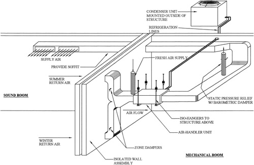
Figure 7.3 is a typical setup for a split AC system. With these units, an air-handler is installed inside the building, while the condenser/compressor for the unit sits outside. This helps to keep the sounds from the condensing unit’s fan in the compressor from entering your space. It’s important to locate the condenser so that it is free from shrubbery and other conditions, as that would reduce the free flow of air to the unit. This would reduce the unit’s efficiency.
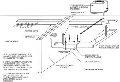
Note the use of isolation hangers for the air-handler unit inside the building. This stops the transfer of vibration from the system into the structure above. Also, note that the duct work is connected to the system through a series of 90° bends in the duct work, which is also important in helping to reduce the transmission of air-handler noise (fan motor, etc.) into the room.
Fresh air is introduced into the system by a ducted connection (to outside air) immediately adjacent to the unit on the return side of the fan. A barometric release (which is also ducted to outside air) is connected into the system to maintain a small amount of positive pressure in the room, while allowing any pressure buildup beyond that to release. This is an important part of the system. Otherwise, the room will achieve the static pressure capacity of the fan and will no longer be able to bring fresh air into the space.
A supply duct running adjacent to the wall/ceiling assembly helps to maintain isolation from above while maximizing ceiling heights in the room.
As far as the duct material you choose to use, it can be lined galvanized duct or a polymer-lined fiberglass duct board, but understand that the lining is an important part of achieving sound attenuation for the system as a whole. Don’t forget, if the duct is galvanized, a canvas connector is required between the duct and air-handler unit to stop the transmission of mechanical vibrations from the fan assembly through the body of the duct work. Fiberglass duct board will not transmit those sounds.
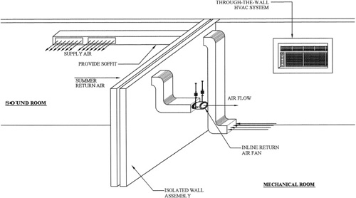
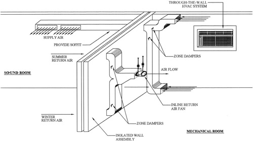
In the tracking room, you can always use a window or through-the-wall unit, if you take care to construct a manner of closing it off when you record. A through-the-wall unit is an air conditioner that installs in a sleeve that goes through a framed opening in the wall. These are similar in nature to the units you see installed in windows, but a through-the-wall unit is a year-round installation, whereas the window unit is typically temporary.
If you picture it, the amount of time it takes you to record is only a few minutes, after which you can always open things back up and turn the unit back on.
This doesn’t really lend itself well to a control room situation, however, due to the fact that you will sometimes spend hours on end while mixing down, with only seconds between stopping and starting between songs, or working the mix on the same songs.
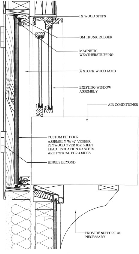
Figure 7.4 is one manner of dealing with the penetration and still maintaining isolation. This is also a very effective isolation system for windows in general.
Mini-split systems offer fairly high efficiency and reduced noise without a large hole in the wall or an open window. By separating the compressor and condenser coil from the fan and evaporator coil, the noisiest component is away from the room. The indoor unit will usually have remote control capabilities and a timer to cycle the system only when needed. The indoor unit is still called an air handler because it has the evaporator coil, blower, and controls inside. The outdoor unit is still called the condenser. They are connected together with refrigerant piping and control wiring, similar to a standard split system. Some of these units employ very quiet fans for the air-handler unit and would be quite compatible with the needs of either control or tracking rooms.
Some manufacturers use low voltage to control the system, while still others use line voltage. Caution must be taken when opening up the cabinet to shut power off when servicing. The most important service item is dirt. Screens or filters can usually be found behind the front grille of the air handler. Tabs allow them to slide out for cleaning. As with the condenser unit on split systems, keep vegetation and debris away from the outdoor unit to allow good air flow for maximum cooling efficiency. An occasional blast from a garden hose with the system shut down will help keep the condenser clean.
Relatively new to the American market, ductless split systems have been in use in Japan and other markets for a long time. Until recently, none were of U.S. manufacture, but increased demand has changed that.
If you intend to go this route, make sure to pay attention to your fresh-air needs because these units do not necessarily provide for this. Even the units that claim to provide fresh air must be looked at closely. I have never been able to determine by looking at any manufacturer’s literature exactly how much air they are providing, and because you are building airtight rooms, that is an important question. When in doubt, design as if they provided none. What little air they may give you could be fine for a home or office, which has normal air infiltration, lots of occurrences where doors open to allow outside air to refresh, and where windows can be opened. That does not mean there is enough air for your airtight rooms.
Portable air conditioners are one of the newest types of air conditioners. Although they still have an exhaust tube that must be vented out somewhere, they are truly portable in the sense that they require no permanent installation.
Portable air conditioners virtually always have caster wheels for portability. They consist of one “box” that holds both the hot and cold side of the air conditioner in one, and they use their exhaust hose (in some cases a duct is required) to expel heat. There are several ways to get rid of the water that the air conditioner condenses out of the air. Most units collect this water in an internal drain bucket, but some exhaust the water through their drain hose while others exhaust the condensate through a duct run to the outside world. Some units have pumps that pump the condensate water out through a drain hose. Most models that collect condensate water in an internal bucket can also be adapted for direct draining.
Since portable air conditioners have both the hot and cold sides of the air-conditioning cycle contained in one box, they have to cool their condenser coil with air they intake from the room they are cooling, and then this air is expelled through an exhaust hose or duct. For this reason, portable air conditioners may create a negative air pressure in the room in which they are run. Air would then be continually seeping into this room from the rest of the house or building to replace the air that the portable air conditioner expels. Some portable air conditioners have solved this problem with a two-hose connection to the outside, one hose to intake air to use to cool the compressor, and one hose to expel this air. In fact, most industrial portable air conditioners use this type of setup. This setup will be required for your space unless you provide another (separate) method for the fresh-air supply.
Some of these systems run quietly enough that operating them in your rooms won’t cause any problems. I’ve heard a lot of home studio owners sing their praises. Your best bet is always to check them out for yourself to decide whether they’ll work for you.
Advantages: No ductwork to install, very small penetration to the outside of the room.
Disadvantages: 13,000Btu systems are the largest (at this time) that provide two-hose connections. Fresh air needs must still be met.
It would be wrong not to cover the evaporative cooler in this book, even though only a very small part of the population can use these systems.
Nature′s most efficient means of cooling is through the evaporation of water. Evaporative cooling works on the principle of heat absorption by moisture evaporation. The evaporative cooler draws exterior air into special pads soaked with water, where the air is cooled by evaporation and then circulated. Evaporative cooling is especially well suited to places where the air is hot and humidity is low, and, in effect, acts not only as a means of cooling the air, but also as a means of providing humidity.
Remember that in climates like Reno, Nevada (one of the examples cited previously), the fresh air will add 0% humidity to the room, and your levels will fall well below the 40% to 45% range that you want to maintain in your studio. These units help you achieve that goal. They are available in either portable or ducted arrangements.
One of the nice features of these systems is the fact that there is no compressor, so operating costs are much lower than with standard air-conditioning systems. A disadvantage of these systems is that they require negative pressure in the space in order to work efficiently. An additional exhaust fan will generally be required to provide that condition. This can be interlocked with the unit for operating purposes.
An exchange chamber is a small room adjacent to your studio, which uses a through-the-wall (or window type) air conditioner to pre-condition the air prior to it being exchanged with the air in your space. The air exchange is then handled through the use of exhaust ducts with inline fans to force the air movement you require.
This is a fairly inexpensive method of providing fresh/conditioned air to your space while maintaining isolation. However, it is contingent on your having a wall above grade to install the unit, as well as being able to devote enough space needed to create the chamber itself. Figure 7.5 is one example of how to construct an exchange chamber.
Until now, we’ve only been looking at the cooling side of the equation. If you’re located in a climate where heating during winter months is a requirement, then it may well make sense for you to consider combination systems that can handle both your cooling and heating needs.
Split system is a term that covers a couple of different type of air-conditioning setups. What it is basically telling you is that there is an interior air-handling unit (basically a fan with a cooling coil) and a separate outside unit. Let’s take a look at some of the options you have with these units.
The air-handler unit for a typical split system can be ordered with either an electric or hydrostatic heating coil (in addition to the cooling coil) as a part of the unit. So the only additional parts required for this system would be a connection of additional power for an electric coil or the connection to your boiler for a hot water loop. The existing ductwork is used for circulation purposes.
One thing you should add to your system, if using this for heat, is a low return for the heating season. This is coupled with damper controls to change the air flow between seasons. The reason for this is simple: heat rises. A high return in the cooling season makes perfect sense, peel away the hotter layer near the ceiling, and the cool air drops to the floor.
In the heating season, though, pulling hot air from the ceiling defeats one of the principles of room heat, and that is creating a thermal layer of warmer air until (finally) at 5′ above the floor, you reach the temperature the thermostat is set to. In addition, as the air cools, it settles to the floor, and it is this cool air that returns to the coil to be reheated and recirculated through the room. This circulation helps to pull warmer air down toward the floor, making it that much more comfortable in the room. Figure 7.6 is the original system with the return duct modified for winter return.
During the heating season, simply close the damper for the upper register and open the bottom damper. Reverse the process during the cooling season.
For climates with moderate heating and cooling needs, heat pumps offer an energy-efficient alternative to furnaces and air conditioners. Like your refrigerator, heat pumps use electricity to move heat from a cool space into a warm one, making the cool space cooler and the warm space warmer. During the heating season, heat pumps move heat from the cool outdoors into your warm house; during the cooling season, heat pumps move heat from your cool house into the warm outdoors. Because they move heat rather than generate heat, heat pumps can provide up to four times the amount of energy they consume.
The most common type of heat pump is the air-source heat pump, which transfers heat between your house and the outside air. If you heat with electricity, a heat pump can trim the amount of electricity you use for heating by as much as 30–40%. High-efficiency heat pumps also dehumidify better than standard central air conditioners, resulting in less energy usage and more cooling comfort in summer months. However, the efficiency of most air-source heat pumps as a heat source drops dramatically at lower temperatures, generally making them unsuitable for cold climates, although there are systems that can overcome that problem.
For homes without ducts, air-source heat pumps are also available in a ductless version called a mini-split heat pump. In addition, a special type of air-source heat pump, called a reverse cycle chiller, generates hot and cold water rather than air, allowing it to be used with radiant floor heating systems in heating mode.
Higher efficiencies are achieved with geothermal (ground-source or water-source) heat pumps, which transfer heat between your house and the ground or a nearby water source. Although they cost more to install, geothermal heat pumps have low operating costs because they take advantage of relatively constant ground or water temperatures. However, the installation depends on the size of your lot, the subsoil, and the landscape. Ground-source or water-source heat pumps can be used in more extreme climatic conditions than air-source heat pumps, and customer satisfaction with the systems is very high.
Through-the-wall HVAC units come in a variety of systems. But they all have one thing in common, they are a complete, self-contained system, and one side of the system is exposed within the room, while the other end is exposed to outside air. A standard air conditioner, the window unit style, is an example of the easiest way to accomplish the installation of one of these units. You can also purchase sleeves that are designed to fit in framed openings in an outside wall for a permanent installation of the equipment.
There are a number of reasons these types of units are preferable to split systems. The first big one is cost. A through-the-wall system can be purchased for roughly 20% of the cost of a similar-sized split system. The next is that they are designed to provide fresh air as a part of their operation, thus handling the need for fresh air within the space. Because of the fact that the fresh air is pulled directly through the cooling coil, dehumidification is handled without the need for additional ducting.
However, one downside is the big hole you just cut through the exterior of your building, and the noise that it will let in and out. Another problem with these units is that the compressor is encompassed within the unit, and, even with quiet units, you can hear these when they turn on.
There are means you can take to use these units unless your actual recording times would be really long. You can install a soundproof enclosure with an interior “door” to close over the opening when you record. You can also tie the power supply into a simple kill switch at your recording desk.
Having looked at the ups and downs to the systems, take a look at the types of systems available to you.
A PTAC unit is a separate encased combination of heating and cooling that is normally mounted through the wall. It has refrigeration components and forced ventilation, and it utilizes reverse cycle refrigeration as its prime heating source. It usually has another heating supplement, generally an electric element heater for backup in the coldest winter days. This type of unit is usually larger than a typical through-the-wall air conditioner and is often seen in motel rooms and apartment buildings.
Any through-the-wall or window unit can be utilized within these chambers. As with any other ducted system, you want to draw the return air from floor level in the winter and near the ceiling in the summer. One thing is different, though, which is that in the winter you will want to draw supply air from the ceiling of the exchange chamber. Refer to Figure 7.7 for details.
The reason for adding the ability to pull air from the ceiling of the chamber rather than the floor (in winter) is due to simple convection. Heat rises, so the warmest air in the space will be at ceiling level, and this is the air you want to feed into your working room.
You also have the option of using totally separate systems for your heating and cooling needs. This can be very beneficial if your existing systems can handle the additional loads.
For example, if you have central air conditioning now, and it can handle your needs (which may well be the case, if it is as overdesigned as a lot of home systems are), then adding some duct and a few motorized dampers to handle flow may well be just what the doctor ordered. It is a lot cheaper than a new system by far. You should realize that most home systems do not have the fresh air that you will need for your room, and that you will probably require some additional dehumidification. However, this way is still cheaper in the long run.
The same goes for heat. If your boiler can handle the additional load, it’s pretty easy to add some more heating to the space. If you do this, I would recommend that you consider the installation of an under-floor heating system. These systems utilize low-temperature water, using PEX (cross-linked Polyethylene) tubing. They produce heat that is uniform through the room, is much less of a drain on your existing system, and is more energy efficient than standard convection systems (i.e., baseboard heat).
Another benefit to these systems is that they are quiet. Typical hot-water baseboard and electric element heaters go through an expansion process when warming up and can cause quite a bit of noise in your room. Although you could work through this, in the case of a control room, it’s possible that mics could pick up the noise in a tracking room and destroy an otherwise perfect take.
With standard convection heating systems, the heating is accomplished by building up thermal layers beginning at the ceiling of the room and working down from there. Eventually, the temperature set at thermostat height (typically, 5′ above finish floor) is reached. It isn’t unusual to have temperatures 10° to 20° warmer at ceiling height than they are at the thermostat. Also, temperatures at floor level are much cooler than they are 5′ in the air.
But with radiant floor heat, the starting temperature at the floor is the controlling factor, with the air cooling off as it rises, and the output from the floor continuing until the thermostat is satisfied.
Not having to develop the thermal layer at the ceiling (before satisfying the needs of the room) means that lower water temperatures can be used, and not having to heat an area of the room that no one comes in contact with (by this we are thinking about the couple of feet directly below the ceiling) means that heating costs are lower. Radiant-floor heating systems typically use water temperatures of 85–140°F (30–60°C), compared with baseboard hydronic systems that operate at 130–160°F (54–71°C) or sometimes 160°–180°F (71–82°C) with older boilers.
Radiant floor systems require special hardware and valve assemblies to work, and they cost more than standard baseboard to install. But if you can afford the initial investment, then the added comfort and slight savings in operating costs would be well worth it.
Oh, one other benefit with these systems, they don’t eat up any wall space, so your walls are completely open for placement of furniture, casework, gear, or whatever your heart desires.
OK, so just how would one go about designing a ducted system for a studio? That’s one of the questions that I have been asked repeatedly since the first edition came out, so let’s see if we can give you at least the basics.
You know how to choose your equipment. You know your fresh air needs and what you need to do regarding humidity (all that info is provided earlier), so what is needed beyond that?
It’s not really rocket science here. In fact it’s pretty simple. For a split system, you begin by sizing the outlet from the air handler large enough to reduce the velocity to not more than double your desired total velocity at the outlets. One note of import here: If you run into an obstacle that will not allow the duct to remain full sized for a short distance, you can introduce a reduction of 25% of the duct size (in volume) for a short distance, after which an increase back to the original will return you to full air flow.
Then do the following:
Provide lining for all supply and return ducts.
Install branch ducting again that is sized to provide no more than double your desired velocity at the outlets.
Or:
Provide a baffle system (sound attenuator) just prior to air entering the room that’s designed to double the volume of the supply duct (a doubling in volume cuts velocity in half, thus achieving your desired supply register velocity).
Use a good-quality supply register to ensure that there is no buffeting of air at the register.
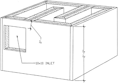
See Figure 7.8 for an example of a plan view for a field-constructed baffle. Figure 7.9 is an isometric view of that same baffle. Note that the outlet is double the size of the inlet, which is necessary in order to maintain the reduced velocity of the air. If they are the same size, then the outlet becomes a bottleneck that reduces the airflow below where you want it.
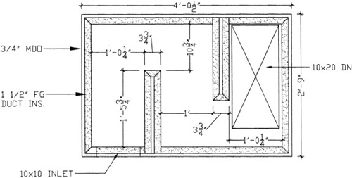
That last part is important unless your velocities are so low that a significant increase in them will not make any difference. The reason is due to the fact that any register introduces a certain restriction in flow. It is not uncommon to see the area of an outlet reduced by as much as 50% with the least expensive Registers/Diffusors. This will effectively double the velocity of your designed outlet.
High-quality registers cost some real money, but in the end they will not introduce noise that you can hear even when they are close to you.
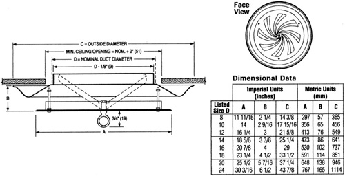
A perfect example of this can be seen in Figure 7.10. This is a high-quality supply register manufactured by Nailor Industries.
![Nailor Industries Series RBD round diffusor.[2][3][4][5]](http://imgdetail.ebookreading.net/design/7/9781435457171/9781435457171__home-recording-studio__9781435457171__graphics__f0156-01.jpg)
The details for this diffusor are shown in Figure 7.11. We’ll look at how you can incorporate this in a ceiling cloud in Chapter 10, “Putting It All Together.”
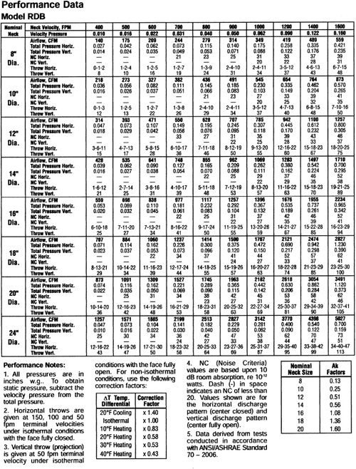
Performance data for this product is shown below in Figure 7.12. Note that if you choose properly, you can get some pretty high velocities while maintaining an NC (noise criteria) less than 20, which is barely above the threshold of hearing. For example, with a vertical throw, an 8” diffusor can deliver 314cfm below 20 NC.
In the following chart you can compare the recommended noise criteria levels for various work areas:
Recommended Nc Criteria | ||
|---|---|---|
Nc Level | Environment | Typical Occupancy |
NC15-20 | Extremely quiet environment, supressed speech is noticably audible. These rooms are suitable for acute pickup of all sounds | Broadcasting Studios, Concert Halls, Recording & Movie Studios, Music Rooms. |
NC30 | Suitable for very quiet office spacs, large confrence rooms. Telephone use is satisfactory. | Residences, Theaters, Librasries, Executive Offices, Director’s Rooms. |
NC35 | Quiet offices, satisfactory for confrence room with a 15-foot table, normal voice usage 10 to 30-feet, telephone use is satisfactory. | Private Offices, Schools, Hotel Guestrooms, Courtrooms, Churches, Hospital Rooms. |
NC40 | Satisfactory for confrence rooms with a 6 to 8-foot table, normal voice range is 6 to 12-feet, telephone use is satisfactory. | General Office use, Labs, Dining Rooms. |
NC45 | Satisfactory for confrence rooms with a 4 to 5-foot table, normal voice is clear at 3 to 6-feet, raised voice at 6 to 12-feet, telephone use is occassionally difficult. | Retail Stores, Cafiterias, Lobby Areas, large Drafting and Engineering Offices, Reception Areas. |
> NC50 | unsatisfactory for confrence rooms with more than 2 or 3 persons, normal voice is clear at 1 to 2-feet, raised voices are clear at 3 to 6-feet, telephone use is slightly difficult. | Computer Rooms, Steno Pools, Print Machine Rooms. |
My goal in studio design is to keep the noise criteria below NC 20, preferably at or below NC 15 if at all possible, which is just slightly above the threshold of hearing. Take a look at Figure 7.13, which is a comparison of the dB levels of various NC ratings for frequencies ranging from 63 to 4,000Hz.
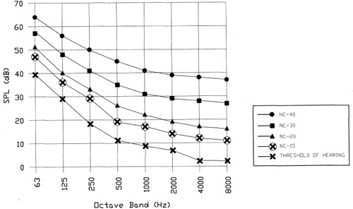
Figure 7.14 lists the sound-pressure levels for various noise criteria levels from NC 15 to NC 65 in increments of 5.
Table 7.14. NC sound-pressure levels.
Noise Criterion | ||||||||
|---|---|---|---|---|---|---|---|---|
Octave Band Center Frequency (Hz) | ||||||||
63 | 125 | 250 | 500 | 1000 | 2000 | 4000 | 8000 | |
Sound Pressure Levels (dB) | ||||||||
NC-15 | 47 | 36 | 29 | 22 | 17 | 14 | 12 | 11 |
NC-20 | 51 | 40 | 33 | 26 | 22 | 19 | 17 | 16 |
NC-25 | 54 | 44 | 37 | 31 | 27 | 24 | 22 | 21 |
NC-30 | 57 | 48 | 41 | 35 | 31 | 29 | 28 | 27 |
NC-35 | 60 | 52 | 45 | 40 | 36 | 34 | 33 | 32 |
NC-40 | 64 | 56 | 50 | 45 | 41 | 39 | 38 | 37 |
NC-45 | 67 | 60 | 54 | 49 | 46 | 44 | 43 | 42 |
NC-50 | 71 | 64 | 58 | 54 | 51 | 49 | 48 | 47 |
NC-55 | 74 | 67 | 62 | 58 | 56 | 54 | 53 | 52 |
NC-60 | 77 | 71 | 67 | 63 | 61 | 59 | 58 | 57 |
NC-65 | 80 | 75 | 71 | 68 | 66 | 64 | 63 | 62 |
All in all, you can see that there is plenty you (or your HVAC contractor) can do to make the HVAC system in your studio quiet (be it home or pro). As long as you stick to the basics, you’ll do fine. Just remember that high volumes and low velocities are your friends in this endeavor, and don’t forget to maintain your room isolation in the process.