
Chapter 9. Cisco HyperFlex
This chapter covers the following key topics:
 Physical Components: An overview of the Cisco HyperFlex and its physical components, which include Cisco Unified Computing System (UCS) nodes and HyperFlex specific appliances.
- HyperFlex Performance Benchmarks: A reference to a performance comparison report that compared the performance of the HX product with other undisclosed competing products. The report focused on different benchmarks for hybrid and all-flash configurations.
- Integration with UCS: Covers the integration between HyperFlex and the widely adopted Cisco UCS. The use of service profiles in defining servers in software and integration with legacy storage area networks (SANs) gives HyperFlex an edge over other vendors.
- Cisco’s HX Data Platform: A detailed description of the HyperFlex data platform. This covers the data platform controller, support of VMware ESXi, Microsoft Hyper-V, and Docker containers. The chapter also covers data distribution in the cache and capacity layers, and the life of read and write input/output (I/O).
- Advanced Data Services: Covers HyperFlex advanced data services including deduplication and compression, snapshots, clones, synchronous replication for backup and disaster recovery, and integration with third-party backup software vendors. Also provides a discussion on HyperFlex security with the use of self-encrypting drives and the adoption of industry security standards.
As early as 2009, Cisco was one of the pioneers in unified computing with the introduction of its Unified Computing System (UCS) offering. UCS was one of the first platforms to integrate compute and networking in a single platform. Cisco worked on integrating UCS with leading storage vendors to create a suite of converged products such as VxBlock, FlexStack, VersaStack, and FlashStack. UCS is widely accepted in many enterprises because it offers ease of configuration and mobility for physical servers.
HyperFlex (HX) is Cisco’s move into the hyperconvergence space with a new product line designed for hyperconverged environments. However, Cisco did not abandon its roots in UCS, and it is part of the HyperFlex system. HyperFlex uses the Cisco HX Series of x86 servers, Cisco UCS fabric interconnect (FI), UCS blade and rack servers, Cisco’s built-in software-defined storage (SDS) software through the acquisition of Springpath, and direct-attached storage (DAS). Cisco HX can support multiple hypervisors, such as VMware ESXi, Microsoft Hyper-V, and KVM (roadmap); it also supports virtualization through containers.
For management, provisioning, and monitoring, Cisco does not move too far from its roots because it adopts the UCS Manager (UCSM) and UCS Director (UCSD) for managing the computing environment. For better integration with existing virtualization management and storage management systems, HX uses VMware’s management plug-ins, Microsoft’s System Central Virtual Machine Manager (SCVMM), and Microsoft Hyper-V Manager. HX also supports Kubernetes for container management in private and public clouds. Cisco designed its own Cisco HyperFlex Connect, a single pane of glass, easy-to-use HTML 5 GUI. Other management products include Cisco Intersight for cloud management as a service. For multicloud, Cisco introduced its CloudCenter product to migrate workloads between private and public clouds. This gives Cisco an edge in extending its already-large footprint in the data center market.
Cisco was one of the latecomers to hyperconvergence for one reason or another. If you think about it, though, Cisco’s strength was always in networking because it had good success with UCS. However, Cisco did not have its own virtualization or software-defined storage software. Similarly, other vendors have their strengths and weaknesses. VMware was strong in software virtualization but weak in hardware. EMC was strong in storage and weak in virtualization and networking.
Cisco was able to enter the software-defined storage market via cooperation with Springpath, which it eventually acquired in September 2017. With Cisco’s roots in networking and unified computing, and the addition of highly innovative software, the HX product line promises to leapfrog other established hyperconvergence solutions.
The following sections discuss the different elements of HX.
HyperFlex Physical Components
One of the highlights of Cisco HX that distinguishes it from other solutions is that it is an extension to its widely accepted UCS platform, which is already adopted into data centers. This ensures a continuity for data center deployments and leverages existing hardware and familiarity with management tools. This point is important because many products from HCI vendors create yet another silo that does not integrate with existing infrastructures.
A key distinction for HX is that it uses compute plus storage nodes, called converged nodes, and UCS compute-only nodes to tailor for the needs of different applications. In some situations, an application has high demand for compute but not much demand for storage, and in other situations an application is compute and storage hungry. In yet other situations the storage requirement is high and requires storage-only nodes. Most hyperconverged products do build combined compute and storage nodes. Some nodes are storage heavy, whereas others are compute heavy. However, finding the right mix that doesn’t leave compute or storage oversubscribed or undersubscribed is difficult. HX offers combined compute and storage nodes and integrates storage-only nodes, but it also offers compute-only nodes via the UCS blade servers. The difference here is in the software’s capability to allow compute nodes to access the pool of storage. With VMware’s hyperconverged product vSAN, which relies on off-the-shelf servers, VMware allows users to add compute-only servers. However, VMware does not recommend building such imbalanced configurations. Although a vendor might physically allow storage and compute imbalances in the nodes, the software might not be able to handle such configurations properly, causing performance hits.
Another difference is in the fact that HX compute nodes do not need extra software licenses for hypervisors or software-defined storage. For compute-only nodes, Cisco offers the IOVisor software, which allows the compute-only node to access the storage pool for free. This capability is important because hypervisors such as VMware ESXi are licensed per central processing unit (CPU), and adding compute nodes with VMware vSAN means extra licenses.
As described in Chapter 8, “HCI Business Benefits and Use Cases,” some high-end enterprise applications such as Oracle’s Database In-Memory and SAP HANA require the databases to be on separate bare-metal servers. Cisco HX allows the integration of bare-metal servers such as the Cisco C460 rack server to gradually add compute and memory.
Cisco HX is packaged in different platforms. Each converged node comes with a solid-state drive (SSD) used as a caching tier. In a hybrid configuration, a node comes with a set of hard disk drives (HDDs) for a capacity tier. In an all-flash configuration, the capacity tier is all SSDs.
The fifth generation (M5) of the HX nodes comes with dual sockets to house one or two Intel Xeon processors with up to 28 cores each. These processors provide high memory channel performance and three Intel Ultra-Path Interconnect (UPI) links across the sockets for high-performance interconnection between the cores. The M5s also support up to 3 TB of memory per server. All HX series servers also have a modular LAN-on-motherboard (MLOM) adapter for Ethernet connectivity without consuming a PCIe slot.
The HX M5 hardware is designed to leverage high-speed interfaces and protocols, such as PCIe with NVMe. This design gives superior bandwidth for connecting NAND flash SSD drives that are used for caching. In addition, the M5 is designed to take advantage of Intel Optane technology with 3D Xpoint memory for SSD drives. This gives high-end applications extremely high performance because 3D Xpoint offers lower latencies and higher density than dynamic random access memory (DRAM) but can deliver multiples of the performance of traditional SSD drives.
Cisco HX also offers support for graphics processing units (GPUs) from leading vendors such as NVIDIA to enhance the performance of graphics-intensive applications, such as 3D graphics in a virtual desktop infrastructure (VDI) environment.
The HX platform continues to evolve to offer small form factor (SFF 2.5") drives and larger densities with large form factor (LFF) 3.5" drives.
It is important to note that currently Cisco does not support mixing different types of HX servers in the same cluster. This might result in different nodes having a different number of drives and different types of drives that might affect performance. However, Cisco allows the mixing of generations, so fourth-generation M4 and fifth-generation M5 of the same HX series can be mixed in a cluster to allow compatibility between generations. The user can build different smaller clusters with each having uniform types of systems and still have everything under the same umbrella management.
HX comes in different types of hybrid and all-flash configurations. All-flash systems are obviously more expensive but provide much higher levels of input/output operations per second (IOPS). Capacity also plays a factor in choosing a system because HDDs still come in higher capacities than SSDs. With LFF drives, users can pack a lot more capacity in a node. However, this comes at the expense of performance, especially in hybrid systems. A hybrid system with a large number of small-capacity drives performs much better than a hybrid system with a small number of large-capacity drives.
The different flavors of the HX nodes are described in the following sections.
Cisco HyperFlex Hybrid Nodes
The HX hybrid nodes use serial-attached SCSI (SAS), serial advanced technology attachment (SATA) drives, and SAS self-encrypting drives (SED) for capacity. The nodes use additional SSD drives for caching and an SSD drive for system/log.
- The HX220c M4/M5: Hybrid node targeted toward small-footprint and small-capacity clusters. This type of node supports up to eight HDD capacity drives for smaller implementations.
- The HX240c M4/M5: Hybrid node targeted toward larger-footprint and high-capacity clusters, such as enterprise business applications. This type of node supports up to 23 HDD drives for larger implementations.
Cisco HyperFlex All-Flash Nodes
The HX all-flash nodes use fast SSD drives and SSD SED drives for capacity. The nodes use additional SSD drives or NVMe drives for caching and an SSD drive for system/log.
- The HX220c M4/M5 AF: All-flash node targeted toward small-footprint high-performance clusters. This type of node supports up to eight SSD capacity drives for smaller high-performance implementations.
- The HX240c M4/M5 AF: All-flash node targeted toward a larger footprint with high-capacity and high-performance clusters. This type of node supports up to 23 SSD capacity drives for larger high-performance implementations.
Cisco HyperFlex Edge Nodes
The HX220c M4/M5 Edge: Hybrid node targeted toward remote office/branch office (ROBO) application.
Cisco HyperFlex Compute-Only Nodes
These nodes contribute memory and CPU but do not contribute to capacity.
- UCS B200: Blade server with the UCS 5108 chassis and UCS 2204 XP, 2208 XP, or 2304 fabric extender
- UCS C220: Rack server with small compute footprint
- UCS C240: Rack server for larger compute footprint
Cisco USC Fabric Interconnect
In the Cisco UCS 6200/6300 fabric interconnect (FI), all nodes in a cluster connect to each other and the rest of the customer network via the Cisco UCS 6200 and 6300 fabric interconnect.
Figure 9-1 shows a sample of the HX physical components. These components are by no means a complete list because more hardware and different configurations are constantly added. Refer to [1] for a complete and updated list.
Figure 9-1 The HyperFlex Physical Components
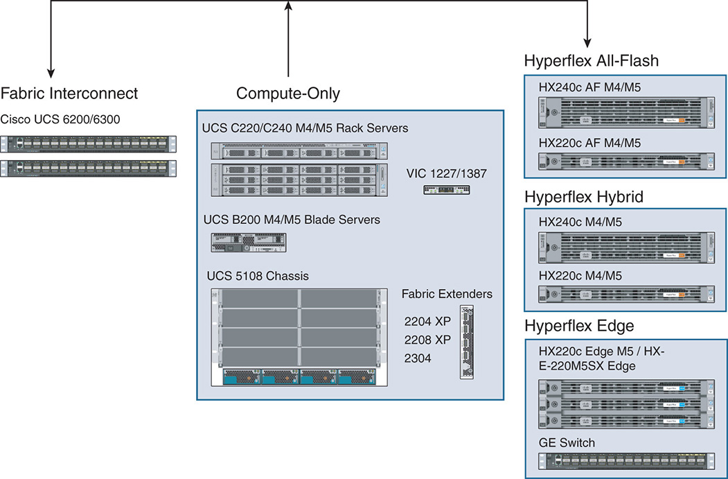
Cisco UCS 6200 and 6300 Fabric Interconnect
Cisco integrates its UCS 6200 and 6300 series fabric interconnect [2] as part of the HX cluster. The switches come in pairs and are dual-homed to the HX series nodes as well as fabric extenders inside the compute-only chassis. The Cisco UCS 6200 series works with the Cisco UCS B-Series server platforms, whereas the Cisco UCS 6300 works with both UCS B-Series and C-Series server platforms. The FI ensures that any two points in the HX cluster are one hop away from each other.
Cisco UCS 6248UP 48-Port FI
The Cisco UCS 6248 FI is a 1 RU, 10 GE, Fibre Channel over Ethernet (FCoE), and fibre channel (FC) switch that offers up to 960 Gbps throughput and up to 48 ports. The switch has 32 fixed 1/10 GE fixed Ethernet, FCoE, and FC (4/2/1 and 8/4/2 Gbps) ports and one expansion slot for the remaining 16 ports.
Cisco UCS 6296UP 96-Port FI
The Cisco UCS 6296 FI is a 2 RU, 10 GE, FCoE, and FC switch that offers up to 1920 Gbps throughput and up to 96 ports. The switch has 48 fixed 1/10 GE fixed Ethernet, FCoE, and FC (4/2/1 and 8/4/2 Gbps) ports and three expansion slots for the remaining 48 ports.
Cisco UCS 6332 32-Port FI
The Cisco UCS 6332 32-port FI is a 1 RU, 40 GE switch that offers up to 2.56 Tbps full-duplex throughput. The switch has 32 × 40 Gbps Quad Small Form Factor Pluggable (QSFP+) ports. Depending on selective ports, the ports can be configured as either 40 Gbps QSFP+, or 4 × 10 Gbps SFP+ breakout ports or outfitted via Quad to SFP adapter (QSA) for 1 or 10 Gbps operation.
Cisco UCS 6332-16UP 40-Port FI
The Cisco UCS 6332-16UP 40-port FI is a 1 RU 10 GE, 40 GE, and native fibre channel switch offering up to 2.43 Tbps full-duplex throughput. The switch has 24 × 40 GE and FCoE ports and 16 1/10 GE/FCoE or 4, 8, 16 Gbps FC unified ports. Depending on selective ports, the ports can be configured as either 40 Gbps QSFP+, or 4 × 10 Gbps SFP+ breakout ports, or as SFP+ universal ports operating at 1/10 Gbps Fixed Ethernet or 4, 8, 16 Gbps FC.
Cisco C220/C240 M4/M5 Rack Servers
The Cisco C220 and C240 are rack servers [3] that integrate with UCS. These servers can be used as part of the HX cluster to offer compute-only systems. The M5 serves as an example offering two-socket Intel Xeon CPUs with up to 28 cores per socket and up to 24 DIMMs for up to 3 TB of memory. The C220/C440 can house the MLOM adapter to connect virtual interface cards (VICs) for 10 Gbps or 40 Gbps Ethernet connectivity.
Cisco VIC MLOM Interface Card
The Cisco UCS VIC [4] is a PCIe MLOM adapter that connects to the UCS servers without consuming a PCIe slot. The Cisco VIC 1227 offers dual-port Enhanced Small Form-Factor Pluggable (SFP+) 10 Gbps Ethernet and Fibre Channel over Ethernet (FCoE). The VIC 1387 offers dual-port 40 Gbps QSFP Ethernet and FCoE ports. The VIC is a next-generation converged network adapter (CNA) that enables a policy-based, stateless, agile server infrastructure that presents up to 256 PCIe standards-compliant interfaces to the host that is dynamically configured as either network interface cards (NICs) or host bus adapters (HBAs). The Cisco UCS VIC supports Cisco’s Data Center Virtual Machine fabric extender (VM-FEX) technology, which extends the Cisco UCS fabric interconnect ports to virtual machines, simplifying server virtualization deployment.
Cisco UCS 5108 Blade Chassis
The Cisco 5108 UCS blade chassis is used to house the compute-only modules B200 M4 and M5 nodes [5]. It comes in a 6 RU chassis that houses half-width or full-width nodes. The chassis houses up to eight half-width B200 M4/M5 compute-only nodes. The rear of the chassis contains two I/O bays for Cisco fabric extender. The chassis offers 40 Gbps of I/O bandwidth per server slot from each fabric extender.
Cisco UCS B200 Blade Server
The B200 comes in two versions: M4 and M5 server nodes. Each node is a half-width blade that fits inside one of the eight half slots of the 5108 blade chassis. The B200 M4/M5 nodes are used as compute-only nodes that do not add any storage capacity; they are used for environments that need only added compute and memory. The B200 M5, for example, offers one or two multicore Intel Xeon processors with up to 28 cores per CPU. The B200 M5 has up to 3 TB of memory and up to 80 Gbps of I/O throughput. The B200 connects via the backplane of the 5108 chassis and to the fabric extenders. The B200 nodes also have an MLOM adapter for optional Ethernet connectivity via VIC.
Cisco UCS XP Fabric Extender
Cisco UCS XP fabric extenders come in different flavors, such as the 2204 XP, 2208 XP, and 2304 models. The fabric extenders multiplex the traffic coming from the B200 M4/M5 nodes that are housed in the Cisco 5108 UCS chassis. The uplinks of the fabric extenders depend on the particular model. The 2204 XP has 4 × 10 GE interfaces that form upward links to the fabric interconnect. The 2208 XP has 8 × 10 GE, and the 2304 has 4 × 40 GE uplinks. Two fabric extenders are inserted in the 5108 chassis.
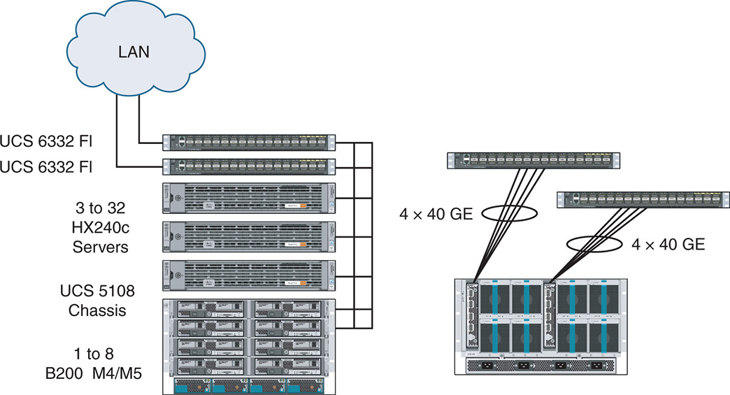
Figure 9-2 shows a sample cluster configuration that contains the HX240c servers and the B200 compute nodes housed in the 5108 blade chassis. The B200 compute nodes connect to the rest of the HX nodes via a fabric extender that multiplexes traffic and connects to the fabric interconnect switches via 10 Gbps or 40 Gbps links.
Figure 9-2 Sample Cluster with HX Servers and B200 Compute Nodes
In the current implementation of HX, a cluster can have a total of 64 nodes with 32 HX converged nodes and 32 compute-only nodes. The cluster requires 3 HX nodes as a minimum to ensure high availability (HA). The number of compute-only nodes cannot exceed two times the number of converged nodes. The maximum of compute-only nodes is 32. When the size of a cluster is reached, you can add additional clusters to the same UCS domain and manage them through the same vCenter server.
HX continues to scale the number of nodes in a cluster. However, it is important to note that although vendors try to differentiate the number of nodes they support in a cluster, the reality is that many enterprises rarely reach those upper limits and stay within the limits of 8 to 24 nodes in a cluster and opt to add more clusters.
For ROBO configurations, Cisco supports the HX220c Edge M5 nodes, which are targeted for small deployments. The Edge system comes with a minimum of three nodes for HA, either as a hybrid or all-flash configuration. However, because ROBO deployments are usually more lightweight than traditional enterprise deployments, the Cisco HX220c Edge M5 nodes can be interconnected with traditional 1 × GE switches normally deployed in a remote office environment.
HyperFlex Performance Benchmarks
Before we get into the details of the HX software architecture, it is worth mentioning that Cisco differentiates itself from other leading HCI implementations based on performance.
Cisco Systems released a performance comparison report that compared the performance of its HX product with other undisclosed competing products. The report focused on different benchmarks for hybrid and all-flash configurations as follows:
- Number of virtual machines (VMs) supported at 5 ms latency
- IOPS and latency for a number of VMs under a certain I/O block size and different read/write percentages
- IOPs and latency for a number of VMs—Vdbench Structured Query Language (SQL) Server Curve Test
- IOPS per VM in an all-flash—Vdbench SQL Server Curve Test
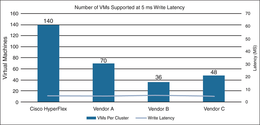
The results of the tests clearly showed the variation in performance between HX and other implementations. The test results, as shown in Figure 9-3, were obtained using workloads that simulate real-world applications. For example, they used 4 KB and 8 KB online transaction processing (OLTP) and SQL Server. The test was run with an OLTP I/O mix of 70 percent reads and 100 percent randomized traffic with the intention to find out how many VMs a system can run while the write latency remains below 5 milliseconds. The test clearly showed that HX maintains the 5 ms latency with up to 140 VM density, a 3× factor from other vendors that started exceeding the latency at around 48 VMs.
Figure 9-3 HyperFlex Hybrid Cluster Scalability Test
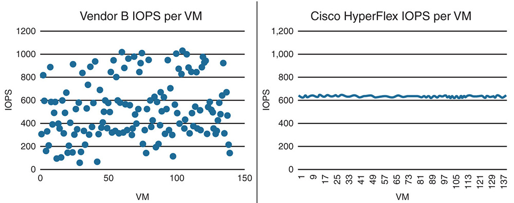
Other tests showed that for HX, the number of IOPS delivered per VM remained fairly constant irrespective of the number of VMs, whereas for other implementations the IOPS varied widely per VM depending on the number of VMs. This benchmark is important because scale-out architectures are supposed to deliver consistent performance results for every VM regardless of the number of VMs. This is shown in Figure 9-4.
Figure 9-4 All-Flash Cluster Performance—IOPS per VM
You can access the full performance test by accessing the link in reference [6].
Cisco offers its customers an HX Bench performance tool based on the Vdbench tool. Vdbench is an open source I/O load simulation tool that was originally created by Oracle. Vdbench gives the user control over parameters such as I/O rate, logical unit number (LUN) size, file size, transfer size, and cache hit percentages. The HX Bench tool puts a simple-to-use HTML5 UI interface in front of this tool, further simplifying the user interaction. You can access this tool with a CCO Login from reference [8].
With HX Bench, Cisco provides a set of profiles with different types of loads to be used to benchmark the performance of your actual enterprise deployment.
Integration with UCS
One of the main benefits of Cisco HX is that although it introduces a new hyperconverged architecture, it blends in with existing data center deployments based on UCS. This capability is important for customers who have already invested in UCS because they do not have to introduce yet another management domain and create additional silos. The UCSM supports all management of the compute components of the relevant UCS series and HX. The Cisco UCSM is embedded in the Cisco 6200 and 6300 fabric interconnect in a clustered active-standby configuration for management traffic and active-active for data traffic. UCSM supports the B200 M4/M5 series blade servers and C220/C240 B4/M5 rack servers in addition to the HX nodes. The HX logical network design is described next.
Logical Network Design
As seen in Figure 9-5 [7], the HX network operates in different logical zones:
- Management zone
- VM VLAN zone
- vMotion zone
- Storage zone
Figure 9-5 HyperFlex Logical Zones
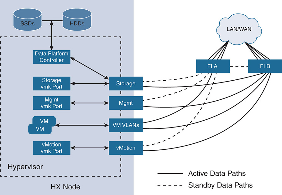
The management zone has all the management connections to the physical components, the hypervisors, and the HX Data Platform controllers running on the hosts. This zone allows management reachability via IP addresses to all users who are managing the platform. It also provides access to services such as the Domain Name Server (DNS) and Network Time Protocol (NTP). The components of this zone include the following:
- Fabric interconnect (FI) management ports
- Management interfaces used by the UCS blades and servers
- HX data controller VM management interfaces
- Roaming HX cluster management interface
- Storage controller VM replication interfaces
- Roaming HX controller replication interface
The VM VLANs zone contains the connections needed to service network I/O to the guest VMs running inside HX. It contains the necessary IP addresses, interfaces, and VLANs so that users on the LAN/WAN can access the VMs. This zone contains a VMkernal (vmk) interface for the VM traffic.
The storage zone contains all connections via IP addresses and interfaces needed for the internal communication between the different elements of the HX distributed file system. The components of this zone include a vmk interface for storage traffic, HX Data Platform storage controller interfaces, and a roaming HX cluster storage interface.
The vMotion zone contains all the necessary connections to allow VMs to move from one host to another during vMotion. This zone contains a vmk interface for the vMotion traffic.
In Figure 9-5, notice the solid lines from the VM VLANs zone to the FIs. The reason is that for I/O data traffic, the FIs work in active-active mode, thus offering the full capacity for data traffic. For other zones such as management, for example, the UCSM runs on active (FI A) standby mode (FI B).
Service Templates and Profiles
As discussed in Chapter 6, “Converged Infrastructure,” UCSM automates the installation of physical nodes by creating service templates and profiles that basically define every single aspect of the server. You use these templates to launch nodes with similar characteristics without having to configure every single parameter every time. Table 9-1 and Table 9-2 show a sample service profile of an HX node.
Table 9-1 Service Profile hx-nodes
Service Profile Template Name |
hx-nodes |
Setting |
Value |
UUID Pool |
Hardware default |
Associated Server Pool |
None |
Maintenance Policy |
HyperFlex |
Management IP Address Policy |
hx-ext-mgmt |
Local Disk Configuration Policy |
hx-compute |
LAN Connectivity Policy |
HyperFlex |
Boot Policy |
hx-compute |
BIOS Policy |
HyperFlex |
Firmware Policy |
HyperFlex |
Power Control Policy |
HyperFlex |
Scrub Policy |
HyperFlex |
Serial over LAN Policy |
HyperFlex |
vMedia Policy |
Not defined |
Table 9-2 Service Profile compute-nodes
Service Profile Template Name |
compute-nodes |
Setting |
Value |
UUID Pool |
Hardware Default |
Associated Server Pool |
None |
Maintenance Policy |
HyperFlex |
Management IP Address Policy |
hx-ext-mgmt |
Local Disk Configuration Policy |
HyperFlex |
LAN Connectivity Policy |
HyperFlex |
Boot Policy |
HyperFlex |
BIOS Policy |
HyperFlex |
Firmware Policy |
HyperFlex |
Power Control Policy |
HyperFlex |
Scrub Policy |
HyperFlex |
Serial over LAN Policy |
HyperFlex |
vMedia Policy |
Not defined |
Note that HX has two different service templates—one for the converged HX nodes (compute plus storage) and one for the HX compute-only nodes. The templates are practically the same except for some variations in specific areas, such as local disk configuration and boot policies.
It is worth noting some of the following policies:
- Boot Policy: UCS defines a Boot policy called HX that indicates where a certain node boots from, and this is applied to all the nodes in the cluster, simplifying server configuration. The HX converged nodes, for example, have their boot files on a pair of secure digital (SD) cards; and the HX compute nodes boot from SD cards, onboard disks, from the SAN, Internet Small Computer System Interface (iSCSI) boot, and so on.
- Firmware Policy: UCS allows the creation of host firmware packages that offer the capability to control the firmware revisions of all blade and rack servers in the cluster. The HX installer creates the firmware packages that contain all the updated firmware. When the HX firmware policy is applied through the service profiles, all components are updated according to the host firmware package.
- LAN Connectivity Policy: The LAN connectivity policy aggregates all the vNIC templates into a single policy to be applied via the service profile. This configures all the networking elements, such as where to obtain the IP and Media Access Control (MAC) addresses and quality of service (QoS) applied to the traffic. A detailed description of the vNIC templates that are aggregated by the LAN connectivity policy follows.
vNIC Templates
As shown in Chapter 6, “Converged Infrastructure,” vNICs are the logical representations for VM LAN connectivity. Depending on the VIC, up to 256 vNICs can be created. Each VM running on the server is associated with at least two vNICs that connect the VM to the fabric interconnects. Because there are two fabric interconnects, notice the representations A and B, where A indicates the primary connection and B indicates the secondary connection. If the VM also requires external fibre channel storage, the VM can have two virtual host bus adapters (vHBAs).
vNIC templates are used to simplify the configuration of the vNICs, and they are referenced in service templates and service profiles. The vNIC templates contain all the configuration of a vNIC, including MAC address pool assignment, the VLANs the vNIC belongs to, quality of service (QoS) policies, network policies, fabric A or B assignment, maximum transmission unit (MTU) size, and so on. A feature called vNIC redundancy allows vNIC templates to be created in pairs. The vNIC template connected to fabric A is considered the primary template, and the vNIC template connected to fabric B is considered the secondary template.
The different types of vNIC templates correspond to the different logical zones that were described earlier: management, vMotion, storage, and VM VLANs. The vNICs templates are as follows:
- hv-management-a and hv-management-b: These are the vNIC templates relative to the vNIC connectivity to the management network.
- hv-vmotion-a and hv-vmotion-b: These are the vNIC templates relative to the vNIC connectivity to the hypervisor’s vMotion network.
- storage-data-a and storage-data-b: These are the vNIC templates relative to the vNIC connectivity to the HX Data Platform distributed storage file system.
- vm-network-a and vm-network-b: These are the vNIC templates relative to the vNIC connectivity to the network that services the I/O to the guest VMs.
A sample vNIC template is shown in Table 9-3.
Table 9-3 Sample vNIC Template
vNIC Template Name |
Storage-data-a |
|
Setting |
Value |
|
Fabric ID |
A |
|
Fabric Failover |
Disabled |
|
Target |
Adapter |
|
Type |
Updating Template |
|
MTU |
9000 |
|
MAC Pool |
Storage-data-a |
|
QoS Policy |
Platinum |
|
Network Control Policy |
HyperFlex-infra |
|
VLANs |
<<hx-storage-data>> |
Native: No |
Notice that the template is associated with FI A; it has a set of parameters that indicate the fabric failover policy, size of MTU, QoS and network control policies, the pool to obtain the MAC addresses and VLANs from, and so on.
Notice the QoS policy platinum and the network control policy HyperFlex-infra. The QoS policy indicates what QoS parameters to enforce on the traffic passing through the vNIC. A system class platinum policy, for example, is assigned to the storage-data-a and storage-data-b templates. It indicates that traffic should be allocated a certain class of service (number 5), no packet drops are allowed, the MTU size of the packet should be Jumbo 9000 bytes, and so on. Other possible policies are gold, which applies to the vm-network-x templates; silver, which applies to hv-management-x templates; and so on.
The network control policy specifies other aspects of the behavior of the vNIC, such as Cisco Discovery Protocol (CDP), MAC address registration, and the actions taken in case of an uplink failure. In this sample template, the network control policy is defined as HyperFlex-infra. The HyperFlex-infra indicates that CDP should be ON, the link should be set to DOWN in case of an uplink failure, and so on.
HyperFlex Integration with External Storage
One of the differentiators of HX is the use of UCS to easily integrate with external storage. HX integrates with existing storage infrastructures via the UCS connectivity to SANs and network-attached storage (NAS). Outside fibre channel storage connects to the fabric interconnect via fibre channel interfaces. Similarly, iSCSI storage connects via Ethernet. Storage devices also connect to the UCS VIC. Interfaces on the VICs are configured, via software, as either FCoE or Ethernet depending on the storage requirement. This enables the customer to work with both SANs and hyperconverged infrastructure and easily migrate traffic. Examples of some applications where HX integrates with legacy infrastructure include
- Boot and run VMs that are stored on the legacy SAN.
- Use the SAN for storage backup.
- Migrate VMs and storage to the newer hyperconverged infrastructure.
- Use raw device mapping (RDM) from the fibre channel array for Microsoft clustering.
By connecting HX to external storage arrays, administrators can connect fibre channel LUNs from an IBM VersaStack or connect to Network File System (NFS) volumes on a NetApp FlexPod. RDM, for example, allows a VM on HX to use the full LUN on a storage array that is used for Microsoft clustering services, thus allowing multiple Microsoft servers to share storage.
To connect to external storage, administrators need to configure additional vNICs (for iSCSI) or vHBAs (for fibre channel). They should be added preferably during the cluster creation or later. During the installation process and UCSM configuration, the user enables iSCSI or FC storage. This creates dual vNICs or dual vHBAs for the service profile templates named hx-nodes and compute-nodes. Also, for each HyperFlex node, dual vNICs and vHBAs are created for the service profiles of the respective nodes.
Cisco’s HX Data Platform
The engine that runs Cisco’s HyperFlex is its Cisco HX Data Platform (HXDP). It is a software-defined storage software that offers distributed storage capabilities over a cluster of converged nodes as well as compute-only nodes. It leverages the Cisco UCS fabric interconnect, the Cisco UCS servers for compute-only nodes, fabric extenders, and new HX converged nodes. Let’s examine the HXDP architecture and software components.
The HXDP is designed to run in conjunction with a variety of virtualized operating systems such VMware’s ESXi, Microsoft Hyper-V, Kernel-based virtual machine (KVM), and others. It also has a way of running the software stack as a Docker container or on bare-metal environments. Currently, Cisco supports ESXi, Microsoft Windows Server 2016 Hyper-V, and Docker containers.
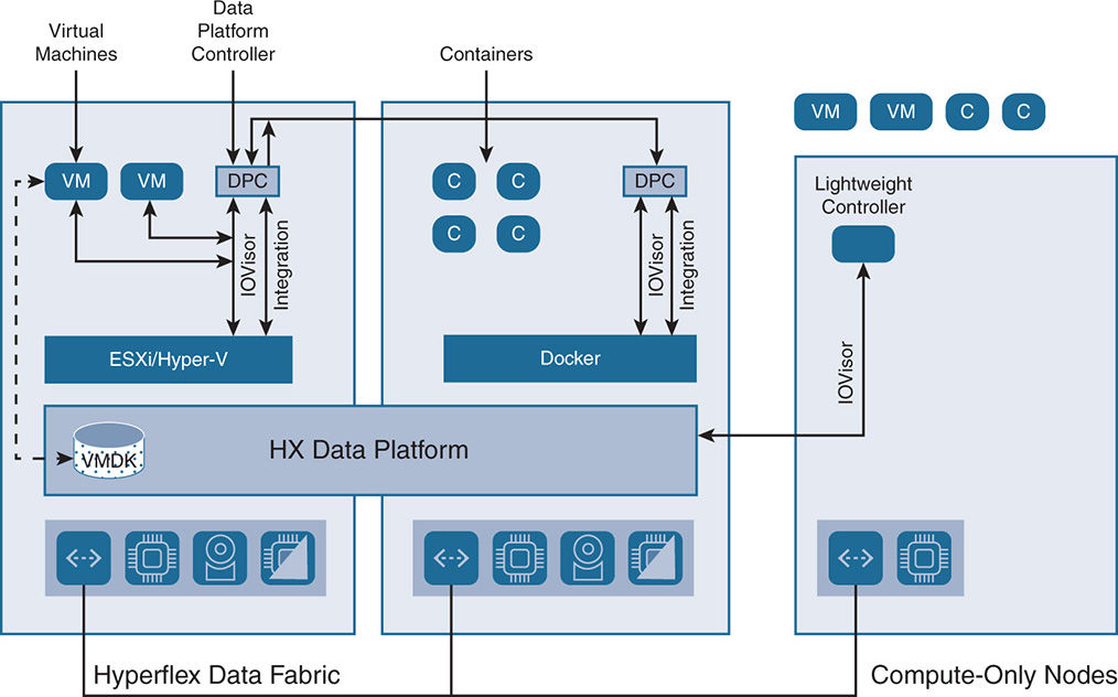
Figure 9-6 shows a high-level view of the HX Data Platform.
Figure 9-6 HX Data Platform (HXDP)
HX Data Platform Controller
The HX Data Platform (HXDP) has a controller that runs as a VM on top of the hypervisor or a container environment. Decoupling the controller from the hypervisor allows the HXDP to run on a variety of hypervisors and container environments. We refer to the Cisco controller in this book as the data platform controller (DPC).
The DPC runs in each node and implements a scale-out distributed file system using the cluster’s shared pool of SSD cache and SSD/HDD capacity drives. The DPC runs on converged nodes and includes a lightweight software layer called the IOVisor. The compute-only nodes run the IOVisor by itself in a stripped-down control VM. The DPCs communicate with each other over the network fabric via high-speed links such as 10 GE or 40 GE, depending on the specific underlying fabric interconnect. Aside from creating the distributed file system, the DPC handles all of the data service’s functions such as data distribution, replication, deduplication, compression, and so on. The DPC uses PCI/PCIe pass-through to have direct ownership of the storage disks. The DPC creates the logical datastores, which are the shared pool of storage resources. The hypervisor itself does not have knowledge of the physical drives; any visibility to storage that the hypervisor needs is presented to the hypervisor via the DPC itself.
The DPC runs as a VM that is allocated a specific amount of CPU and memory resources to ensure proper performance. As such, the DPC VM needs resources to operate as it is doing the heavy lifting for the I/O functions. The following are recommendations for the resources for the DPC on different HX nodes:
- Compute: The HX 220 and 240 nodes require at least eight vCPUs for good performance.
- Memory: The HX 220 requires 48 GB of memory, and the HX 240 requires 72 GB of memory.
The compute-only nodes have a lightweight controller VM to run the IOVisor that requires only one vCPU and 512 MB of memory.
As seen in Figure 9-6, the DPC integrates with the hypervisor using two preinstalled drivers: the IOVisor and an integration driver for specific integration with the particular hypervisor.
The IOVisor gives the HX Data Platform the flexibility to interact with the hypervisors for accessing and presenting I/O functions dynamically. Some of the general use cases of the IOVisor in HX Data Platform are
- The IOVisor is used to stripe the I/O across all nodes. All the I/O toward the file system—whether on the local node or remote node—goes through the IOVisor.
- The IOVisor allows compute-only nodes such as the B-Series and C-Series servers to have access to the storage pool to provide additional compute and memory resources. The I/O is sent through the IOVisor from the compute-only nodes to the storage nodes. This differentiates HX from other implementations that cannot leverage compute-only nodes to access existing storage. Some HCI implementations do offer compute-only nodes, but such implementations create a one-to-one mapping between a compute-only node and a storage node. This creates a hotspot because all VMs on the compute-only node use the one node in the cluster for storage. HX, in contrast, leverages the IOVisor to offer the compute-only nodes access to the full datastore that is created by all storage nodes.
HyperFlex in VMware ESXi Environment
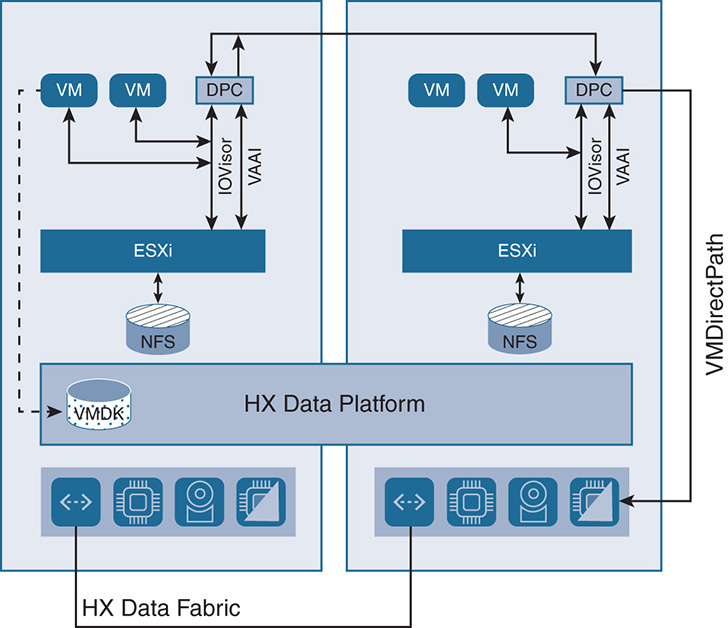
When ESXi is run as a hypervisor, the DPC bypasses the hypervisor when accessing the physical resources. The DPC PCI/PCIe pass-through is done via the VMware VMDirectPath feature.
VMDirectPath allows the DPC to have PCI/PCIe pass-through control of the physical server disk controllers without any intervention from the hypervisor. This is done with hardware assistance from the CPUs with mechanisms such as Intel Virtual Technology for Directed I/O (VT-d). This ensures high performance in having the VM access the hardware resources directly. VMDirectPath gives the most savings in CPU cycles with high IOPS environment; it is powerful in the sense that it gives the HXDP the flexibility to implement features independent from the hypervisor and apply hardware assistance to these features when needed.
The DPC integrates with ESXi using three preinstalled vSphere Installation Bundles (VIBs). Think of them as drivers that are installed in the hypervisor to deliver specific functions:
- IOVisor: The VMware IOVisor VIB presents the storage to ESXi as a regular NFS mount datastore. However, at this point, the HX Data Platform does not use the NFS file system to deliver file-sharing services. This is just to give ESXi visibility into the storage. The IOVisor also intercepts I/O from the VMs and redirects all I/O to the data platform controllers for load sharing across all nodes.
- VAAI: The vStorage API for Array Integration (VAAI) is a set of application programming interfaces (APIs) that were originally defined by VMware to offload some of the advanced storage functionality, such as snapshots, cloning, and thin provisioning to the storage arrays. This allowed vendors to offer hardware assistance to I/O functions offloading the host CPU from spending cycles. This evolved to vSphere APIs for Storage Awareness (VASA) and the notion of virtual volumes (VVols) in later versions of ESXi to also give more transparency to executing such functionality outside ESXi.
In the context of the HX Data Platform, VAAI allows vSphere to request advanced functionality, such as snapshots and cloning, through the HX data controller. In turn, the DPC performs such functionality through the manipulation of metadata without doing expensive data copying. Snapshots and cloning are discussed further in this chapter.
- stHypervisorSvc: This VIB offers enhancements and the needed features for the HX Data protection and VM replication. This module coordinates the snapshot process in the background and facilitates the replication of snapshots between clusters.
ESXi support is shown in Figure 9-7. Note that ESXi sees the storage as an NFS datastore.
HyperFlex in Hyper-V Environment
HX multi-hypervisor support includes support for Microsoft Hyper-V and support for the SMB3 file protocol. HX implements the Microsoft Windows 2016 Data Center Core and supports Hyper-V features. It also supports new Microsoft application stacks with native failover clustering, checkpoints, replica, and Active Directory (AD).
For added integration with existing environments, the Hyper-V hosts are managed via Microsoft’s System Center Virtual Machine Manager (SCVMM), Microsoft Hyper-V Manager, and PowerShell. This allows integration with existing applications such as backup software for Microsoft applications. Integration with the HX Data Platform is also delivered via a set of HX RESTful APIs and Cisco Connect HTML5 GUI. The high-level architecture is shown in Figure 9-8.
Figure 9-8 Support for Hyper-V
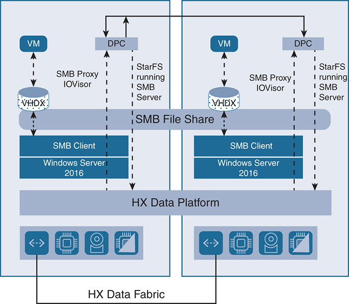
Notice that Windows Server 2016 is installed. The DPC forms the HX datastore that is presented to the VMs on Hyper-V as a Server Message Block (SMB) file share. Microsoft applications have the virtual hard disk X (VHDX) files running on the SMB file share. The VHDX files in Microsoft are similar to logical hard drives that contain all sorts of information such as operating system and data. Similar to the ESXi environment, the VMs use IOVisor to redirect the I/O to all the nodes on the HX datastore. However, for Hyper-V, there isn’t a notion of VAAI as in ESXi; instead, Microsoft Server implements a layer called Offload Data Transfer (ODX), which is similar to VAAI in the sense that it offloads storage functionality to the underlying storage layer without involving the host. The ODX performs functions such as cloning, taking snapshots, and copying files directly between storage devices without going back to the host VMs.
Docker Containers Support and Volume Driver
Containers have found increased adoption among the developer community in the past few years mainly because they are lightweight, consume less memory and storage resources, and launch much faster than VMs. Containers bring to the table new levels of agility and speed in launching and modifying applications. In the containerized environment, Docker containers have found wider adoption, possibly because Docker was one of the early movers in licensing the technology.
Containers were first adopted in the cloud environment, where thousands of applications were deployed. However, container adoption in the enterprise is still struggling due to many challenges that administrators must overcome. The challenges fall in the area of container management and monitoring, ways to integrate containers in an existing environment, the engineering skill set needed to work with containers, and so on.
To that regard, Cisco started a partnership with Docker in 2017 to work on different areas to simplify and enhance the deployment of containers in enterprise environments. The Cisco and Docker partnership spans different areas including networking, security, orchestration, and data management.
HX supports a Docker container environment to run applications and enable developers to have an environment similar to cloud services. When running containers in the cloud, you normally request a certain amount of persistent storage to run applications. Such storage gets automatically configured on demand without your knowing what goes on behind the scenes. In an enterprise environment, things can become more complicated. Virtualization engineers need to request storage from storage engineers. In a containerized environment, allocating storage is a little more complex. Containers are normally transient in nature, and so is the storage associated with them. Normally, storage is associated with the container’s union file system. The container union file system has multiple read-only layers and a read/write layer. When changes are made to a file, they go into the read/write layer. When a container is deleted, all the changes are gone, and you are left with the read-only layers.
Also, containers run on bare-metal servers in addition to VMs. When running on VMs, a container can move from one VM to another, and as such, it needs to keep its persistent storage. The complexity of keeping persistent storage for containers depends on the type of back-end storage. So, to save data to persistent storage and share data between containers, Docker implements container volumes.
Container volumes are files and directories that sit outside the union file system and can be saved on the host or on shared storage and can be accessed by multiple containers.
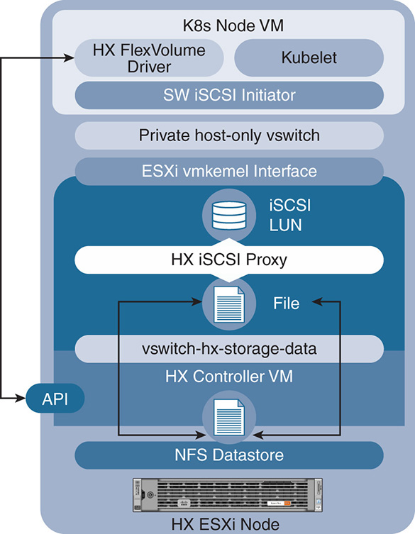
Cisco implements the Docker volumes using the FlexVolume Driver, as shown in Figure 9-9.
As you’ll notice, the containers are run inside a VM. The FlexVolume driver allows the user to request storage on demand, and that storage is allocated outside the container union file system, so it can be saved and shared by multiple other containers. Data volumes are allocated via block storage. The FlexVolume allows storage to be requested from the HX Data pool by presenting the block storage as an iSCSI LUN.
The existence of the containers inside VMs and the use of FlexVolume give containers the same resiliency that HX applies on VMs. VMs and their data—and hence containers and their data—benefit from all the data services such as snapshots, replication, deduplication, compression, and so on.
The area of containerization continues to be a moving target as the technology continues to evolve. Cisco is continuously evolving the containerized architecture to allow containers to work inside VMs as well as directly on bare-metal servers. The Cisco container platform puts together a lot of open source tools to create effective ways to manage Kubernetes clusters, including the storage and networking components.
Figure 9-9 Docker Container Environment
HyperFlex Data Distribution
HX has a highly distributed architecture that leverages every single component in the cluster and treats resources as a shared pool. HX data distribution through the use of data platform controllers, data replication, cluster resiliency, and the life of reads and writes inside the system are discussed next.
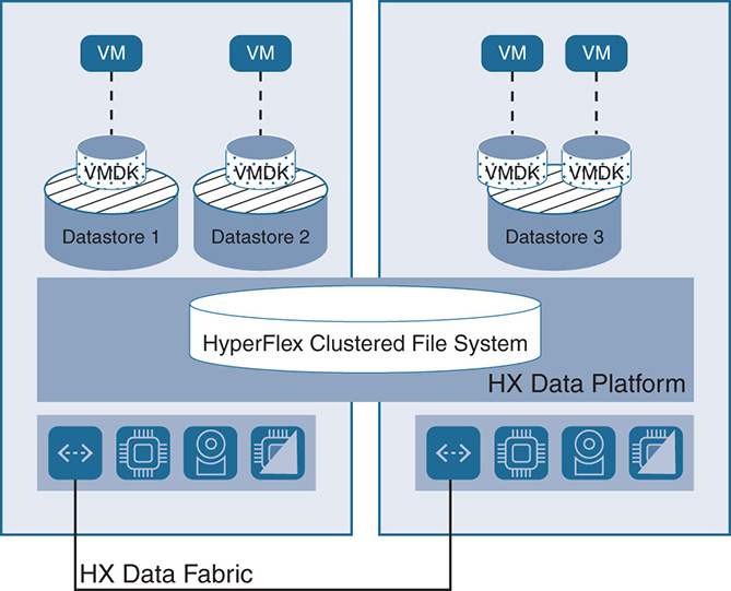
The HXDP distributed file system, using the DPC VMs, creates a pool of storage that is shared by all nodes. The shared pool of resources can be divided into different datastores. There is no one-to-one relation between the datastores and the physical nodes because the data is distributed across multiple nodes. The VMs use the datastores to store their virtual machine disks (VMDKs). The only restriction is that a VM needs to keep its VMDKs in a single datastore. This is needed to do snapshots and clones on the VM level. HX creates an even distribution of data among all the physical nodes. When a VM requests a certain space for a VMDK, the space is allocated by leveraging disks from all nodes. This creates a high disk space utilization compared to implementations that lock the VMDK to the nodes where the VM exists. Such implementations normally create an uneven distribution of storage on disks and a low utilization.
Datastores are created via the vSphere web client or the HX Connect User Interface (UI). Datastores are automatically “thin provisioned.” The size of the datastore is increased or decreased as needed based on the requirement of the application with no restriction on the size of the datastore because it is not tied to any specific physical disk. The HyperFlex system monitors the total thin-provisioned capacity of the cluster to ensure that it is less than the actual usable physical capacity. The system alerts the user when the actual storage consumption results in low amounts of free space. The alerts are sent to the user via emails from the vSphere plug-in on HX connect. Datastores are illustrated in Figure 9-10.
Figure 9-10 HyperFlex Datastores
The DPC handles all read and write operations from the VMs to their respective VMDKs that are stored in the distributed datastores in the cluster. Many of the DPCs participate in these operations at the same time. HX uses two tiers of data: a caching tier and a capacity tier. A hybrid HX node has one SSD drive used as a read/write log cache, and HDDs for capacity. An all-flash node has an SSD or NVMe drive for a write log and SSDs for capacity.
HX does dynamic distribution of the data leveraging storage and compute resources in the cluster. This is done by striping the data over multiple disks and nodes and using replication when needed and according to protection policies. A major difference for HX is that it uses a highly distributed approach leveraging all cache SSDs as one giant cache tier. All cache from all the nodes is leveraged for fast read/write. Similarly, HX uses all HDDs as one giant capacity tier.
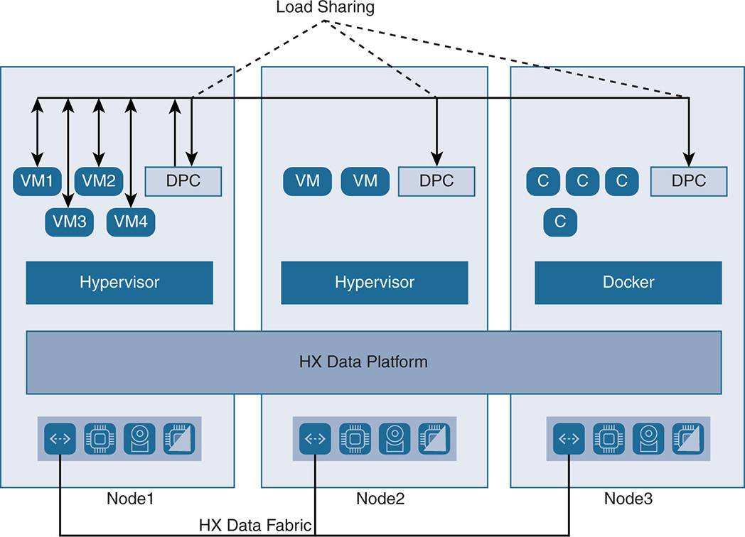
The HX distributed approach uses HX DPCs from multiple nodes. The controllers run inside a VM on top of the existing hypervisor or Docker. The distributed approach where all nodes share the I/O for all VMs eliminates hotspots if multiple VMs in the same node put stress on the local controller. In this case the local controller engages other controllers from other nodes to share the load. This scenario is represented in Figure 9-11. Notice that the workloads and data services for VMs 1 to 4 are shared by the local DPC on node 1 and the remote DPCs on nodes 2 and 3, where nodes 2 and 3 are also used for I/O. The purpose is to eliminate any hotspots in any single node. Other HCI implementations on the market use what is called strict data locality or partial data locality. With such implementations, I/O basically follows the VM, and the preference is to do the writes on the node where the VM is located, which might create hotspots.
Figure 9-11 HyperFlex Controller Sharing
HyperFlex Data Striping
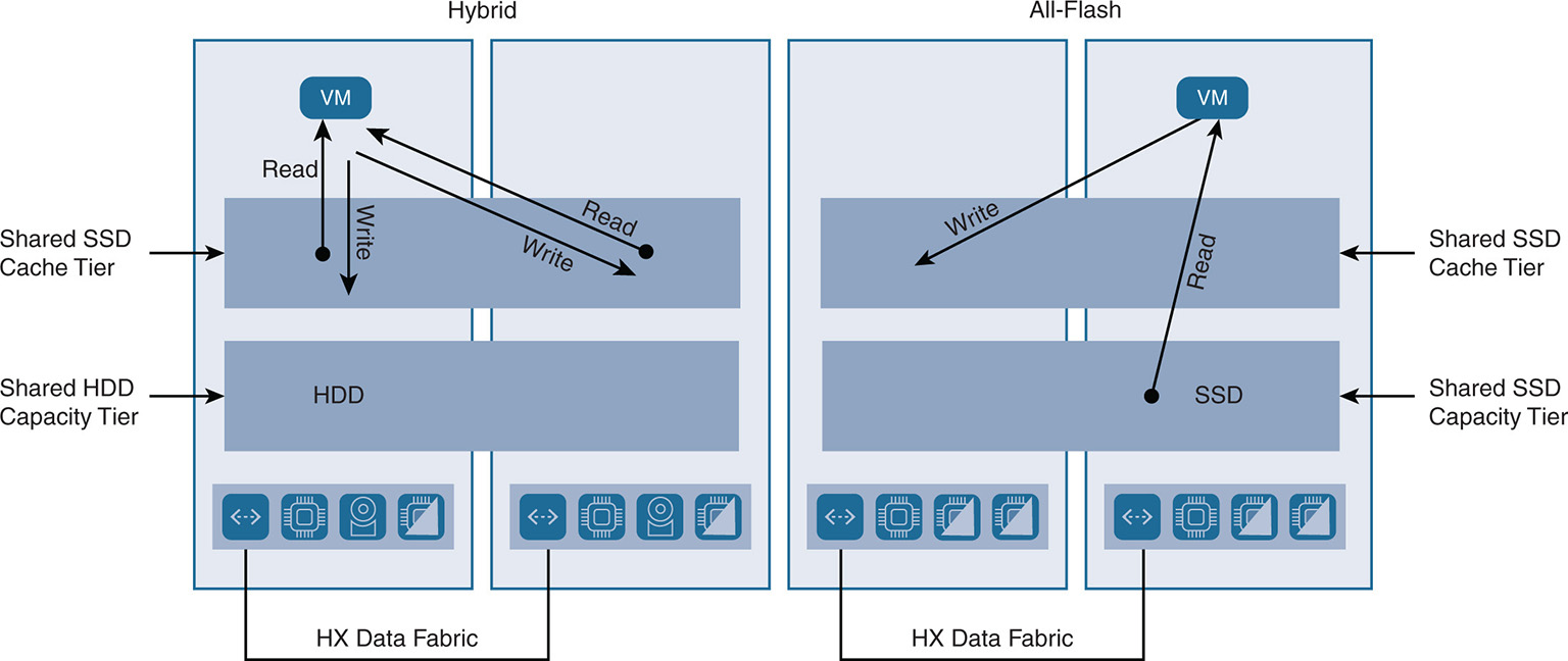
HX uses the caching layer as an L2 read cache in hybrid configurations and as a write cache for both hybrid and all-flash configurations. HX moves away from data locality, as in other hyperconverged implementations, and adopts a fully distributed system leveraging resources across the fabric. HX treats all caching devices from all nodes as one caching pool where a VM can leverage the cache from its own node and in other nodes in the cluster. This configuration is shown in Figure 9-12.
Note that for a hybrid node, the read and write are done using the SSD cache. In an all-flash configuration, the reads are done directly from the SSD capacity tier or the cache tier (if the data is still in the cache). Note also that any of the local or remote cache can be used in all nodes as one large pool.
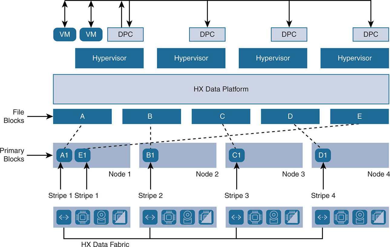
The data is striped between all the SSDs in the caching tier of the cluster. A file or object such as a VMDK is broken in smaller chunks called a stripe unit, and these stripe units are put on all nodes in the cluster. A stripe unit could be 256 MB, for example, and the number of stripes could be 1, 2, 3, and so on. If the total number of converged nodes in a cluster is 32, the maximum number of stripes is 32. Stripe units are placed on the nodes using a hashing algorithm performed by the IOVisor, which determines where to place the primary blocks.
Figure 9-12 Read/Write Operation Hybrid Versus All-Flash
An example is illustrated in Figure 9-13. In this example, four stripes are selected, so an object VMDK whose data is represented by blocks A, B, C, D, and E, is striped over the four nodes. In this case, primary block A1 goes to node 1, primary block B1 goes to node 2, primary block C1 goes to node 3, primary block D1 goes to node 4, and primary block E1 loops back to node 1, and so on. The index 1 in A1, B1, C1, D1, and E1 indicates that these are the primary blocks.
Data Protection with Replication Factor
In addition to data striping, a protection policy can be applied to protect the cluster from disk or node failure. This is done via replication of the data over multiple nodes. HX has a default replication factor (RF) of 3, which indicates that for every I/O write that is committed, two other replica copies exist in separate locations. With RF = 3, an HX cluster can withstand two simultaneous disk failures on different nodes or two node failures, where the data is recovered without resorting to any other backup and restore methods. If RF = 2, a total of two copies can withstand one failure.
In the example shown in Figure 9-14, if a replication factor of 3 is applied (RF = 3), the stripe units are replicated onto two more nodes in addition to the primary node.
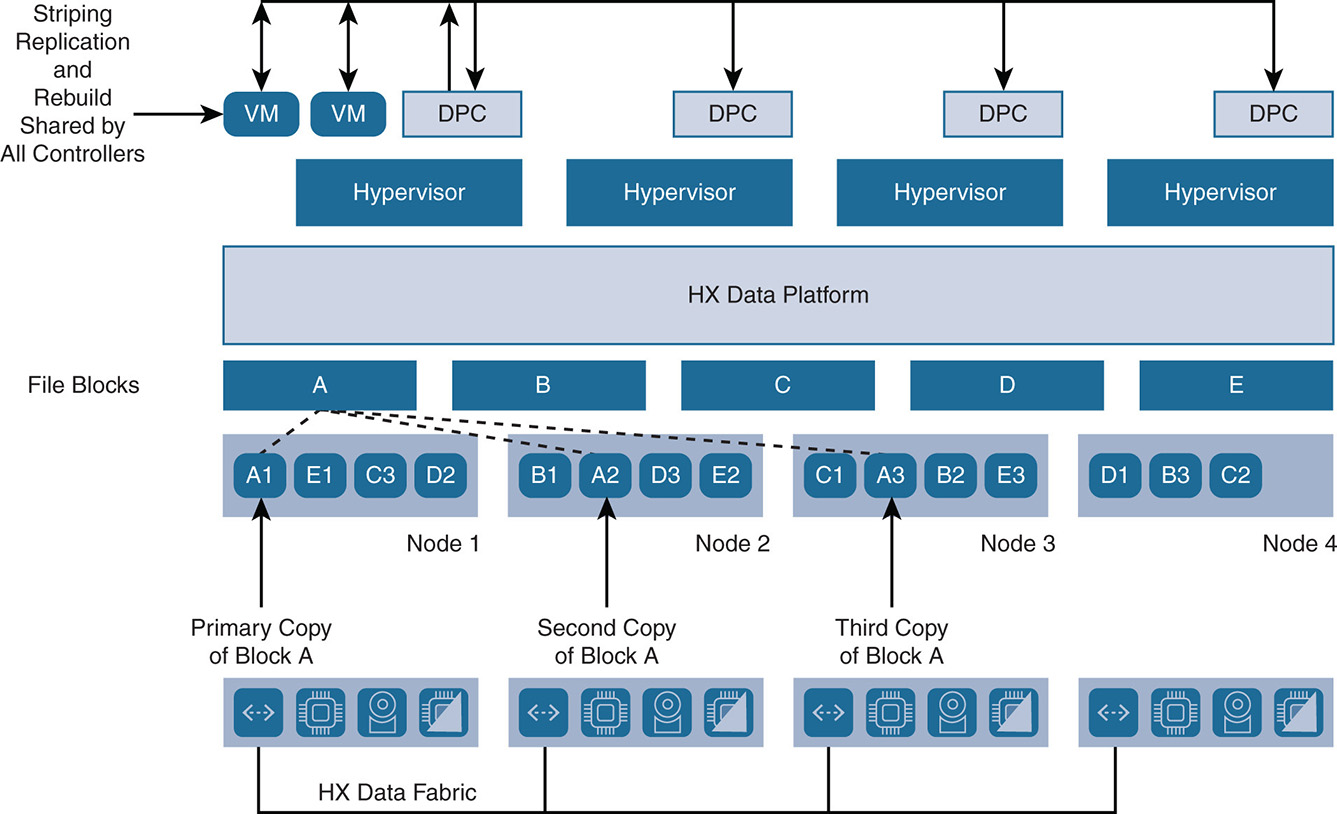
Note that block A is replicated on nodes 2 and 3 as A2 and A3 to indicate the second and third copies. The same is done for blocks B, C, D, and E. Also note that a stripe unit is always replicated on different nodes than the original node so that the original and the copy are not lost at the same time. In case of a disk failure, the data is recaptured from the remaining disks or nodes. In this example, if node 4 fails, the stripe units for D, B, and C are still available on nodes 1, 2, and 3. In such cases, the VMs that were running on node 4 are redistributed to other nodes using VM high availability, and the VM has access to their data. Upon the failure of node 4, you lose the replication policy RF = 3 because data now has only two copies. If for some reason node 4 does not come back online, the data blocks that were lost on node 4 will be replicated on the other nodes to maintain RF = 3. This happens automatically after two hours or sooner with user intervention.
After restoring the disks or node, the data on that disk or node is rebuilt according to the striping and replication policies, and the data is rebalanced between all nodes. One advantage of the distributed architecture is that all data platform controllers participate in the striping, replication, and rebuild. If a failed node does not come back online, the rest of the nodes participate in rebuilding the failed node so that any single node does not have any hotspots.
Disk failure does not affect the VMs at all because the VM continues to access its data from other nodes. The data that was influenced by the disk failure can be reconstructed on other disks in a matter of minutes, depending on the replication policy, to have the system back in a healthy and protected state.
The capability to move the data around and rebalance the system after failures makes one-click software updates viable because you can easily take a node offline, update the software and firmware, and then bring up the node again.
Cluster Resiliency
Rebalancing occurs in a cluster when it is self-healing and recovering from a failure. Failure occurs on a node when a disk fails or when the controller fails or when the node itself fails. As discussed previously, when a disk fails, there is no impact on the VMs and I/O because the data is already available on other disks in the cluster. However, the system needs to rebalance the data to put the lost data on other disks to maintain availability in case another failure occurs. Similarly, when a DPC fails, the I/O that was serviced by that controller is rebalanced by being sent to other controllers in the system. So also in this case, a DPC failure does not impact the VMs or the I/O on the particular node, but the I/O load gets rebalanced on other nodes. Rebalancing also occurs if a node recovers after failure and gets added to the cluster or in scale-out scenarios where more nodes are added to the cluster.
Failures in a node can be simultaneous when the node incurs a failure while still unhealthy and is still recovering from a failure. Failures are considered nonsimultaneous when a recovered and healthy node incurs another failure. HX is particular about how failures are handled to maintain data integrity. HX allows the user to set resiliency policies depending on the failure tolerance in the cluster. Because a node might take up to two hours to self-heal, it is important to ensure that the system has a level of fault tolerance while recovering. This is the reason HX starts with a minimum of three nodes; this way, when a node failure occurs, the system is still fault tolerant. The resiliency policies range from having a cluster allow full read/writes during node failure (Lenient), to allowing read-only (Strict), to taking the cluster offline. A sample of resiliency policies for node failures and HDD failures is shown in Tables 9-4 and 9-5. A sample cluster status is shown in Table 9-6.
Table 9-4 Cluster Resiliency Policies for Node Failures
Number of Simultaneous Node Failures |
Cluster Size = 3 |
Cluster Size = 4 |
Cluster Size = 5+ |
1 |
Read/Write |
Read/Write |
Read/Write |
2 |
(offline) |
(offline) |
Read-Only |
3 |
(offline) |
(offline) |
(offline) |
Table 9-5 Cluster Resiliency Policies for HDD Failures
Number of Simultaneous HDD Failures (Across Different Nodes) |
Cluster Size = 3+ |
1 |
Read/Write |
2 |
Read-Only |
3 |
(offline) |
Status |
Online |
Health State |
Healthy |
Policy Compliance |
Compliant |
Space Status |
Normal |
Replication Factor |
2 |
Access Policy |
Strict |
Reason |
Storage cluster is healthy |
Note how the policies are set to show the behavior of the cluster depending on the number of node or disk failures. The access policies can be set to Strict, for example, to indicate that at least two instances of all data blocks must be available for the cluster to be read/write. A Lenient access policy indicates that the cluster remains read/write even if only one instance of the data blocks remains. The tables show an example where a cluster with three nodes automatically goes offline if more than one node failure occurs. A cluster of five or more nodes goes into read-only mode if two node failures occur and goes offline if three node failures occur. A cluster of three nodes goes offline if three simultaneous HDD failures occur across the cluster. These measures can be taken to ensure the cluster reacts if systematic failures start to occur, which means that a major issue is taking place. In those cases, it is better to put the cluster in read-only mode or offline rather than experiencing data corruption.
Logical Availability Zones
Cisco HX supports logical availability zones (LAZs) to separate the cluster into failure domains. The LAZ concept applies only to the HX series nodes and not the compute-only nodes. In its first iteration Cisco HX is configured to automatically divide a large cluster into multiple failure domains. Data is not replicated within the same LAZ. This ensures that if a failure occurs to multiple nodes in the same failure domain, data is still available or can be reconstructed. LAZs allow a cluster to sustain a larger number of nodes or disk failures because of the multiple fault domains. Further extensions to logical availability zones allow manual configuration so the user can define what set of nodes constitute a failure domain. This is done around different boundaries such as nodes in rack, nodes in a data center, or nodes that have the same power source.
LAZs create the foundation for building stretched clusters between different data centers. However, as you will see in more evolved implementations of failure domains, there is always the headache of having network segmentation if fault domains become isolated. In such cases, “witness” nodes must be created to avoid race conditions, where the same VM gets created in different fault domains. Failure domains are covered further in Chapter 12, “VMware vSAN.”
Details of Read and Write Operations
Each HX node contains a caching tier and a capacity tier. HX uses a log structured file system for writing and reading data from both the cache and capacity tiers. In addition, the HX contains a data virtualization layer that decouples servicing the data from the actual physical location of the data on disk. The use of the log file system, the details of the virtualization layer, and the lifecycles of read and write for both cache and capacity tiers are discussed next.
Log-Structured File System
HX adopts a hardware-agnostic log-structured file system (LFS) that is written in the Portable Operating System Interface (POSIX) user space code. This LFS gives HX the flexibility to have the compute layer access data as files, objects, blocks, or via API plug-ins. The HX file system uses mainly objects to store information, but it presents an NFS datastore toward the ESXi hypervisor or an SMB3 datastore toward a Hyper-V hypervisor.
The log-structured approach gives HX many advantages in accessing both HDDs and SSDs compared to traditional write-in-place file systems. Unlike with write-in-place file systems where the data is written in different places, with LFS, information is always written sequentially, which improves seek times for reads and writes for HDDs. Also, because the same blocks are not modified and written in the same space as in traditional write-in-place file systems, LFS extends the life of flash devices and gives better write latency by avoiding the write cycle of writing into existing flash cells. To remove old data from the log, HX uses a cleaner that operates on a schedule or a free space threshold, depending on what is appropriate for the amount of capacity used in the system. The cleaner operates daily if not executed by the threshold.
Also, the index of a block, or metadata, is the result of a hash function that gives the block a unique identifier. By looking at the index of the block, you can tell whether the block changed or not. If the block did not change and there is a write operation for the same block, the block remains intact and does not have to be written again. The LFS also gives better advantages to write-in-place file systems when data is being compressed. With traditional write-in-place file systems, if the data is to be modified and it is already compressed, the system must do a read, decompress, modify, compress, and then write. In LFS, because the new data is appended to the log, it is just compressed and written. This gives huge performance advantages.
Data Virtualization
HX data platform contains a virtualization layer that decouples servicing the data from the actual physical location of the data. This ensures consistency in performance when VMs move around because the performance is consistent regardless of where the data resides. HX uses the concept of pNodes and vNodes. The pNode is the actual physical node. A vNode is an abstraction that decouples the data from the physical node. The three types of vNodes are as follows:
- Cache vNode: The cache vNode is the data that exists in the cache tier. The data is not deduplicated, but it is compressed. The more cache vNodes you have, the faster the data will be processed.
- Data vNode: The data vNode is the actual data such as files, objects, and database data. This data is in the capacity tier, and it gets deduplicated while moving from the cache to the capacity tier.
- Metadata vNode: The metadata vNode has all the metadata information about the data itself. The metadata also contains the hashing key of the data, which helps in determining whether to deduplicate or compress the data.
Figure 9-15 shows how stripe units from different VMDKs map into the cache vNodes.
Figure 9-15 Data Virtualization
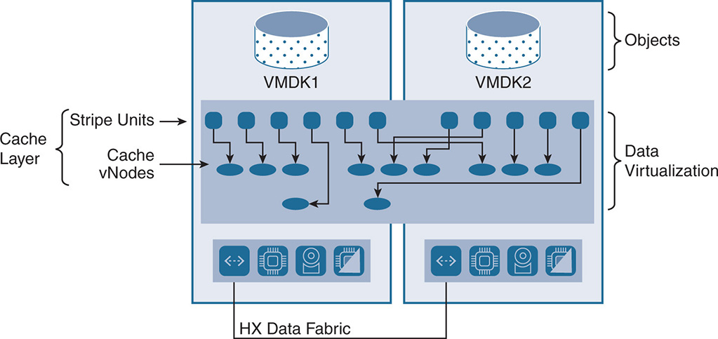
The stripe units from the VMDKs map into cache vNodes, which represent a virtual node that is used to address the data. The virtual node in turn maps into different physical nodes. This creates a mapping structure between stripe unit cache vNodes and pNodes and the mapping is tracked in the HX cluster resource manager. Having cache vNodes allows HX to rebalance the information in the cache to avoid hotspots, by moving the cache vNodes between different pNodes. This means that a VM running on node 1 could have its caching for a certain VMDK done on node 4, and the system has to deal with this.
Addressing a stripe unit into cache vNodes utilizes a combination of consistent hashing and a mapping service to map the stripe unit to the cache vNode. If multiple stripe units hash to the same location, the mapping service can move the stripe unit to a different location and track it. Also, as vNodes move around between caches, the mapping service needs to keep track of the location of the data.
The Lifecycle of a Write Operation
When an application performs a write, the VM sends the data to its VMDK. The IOVisor intercepts the write operation and sends it to the primary controller that is servicing the VMDK. The write operation in the caching tier is performed by doing an I/O write to the caching SSD of the local node in the write log area and striping the data between the cache SSDs of the different nodes in the cluster. This is done using an LFS.
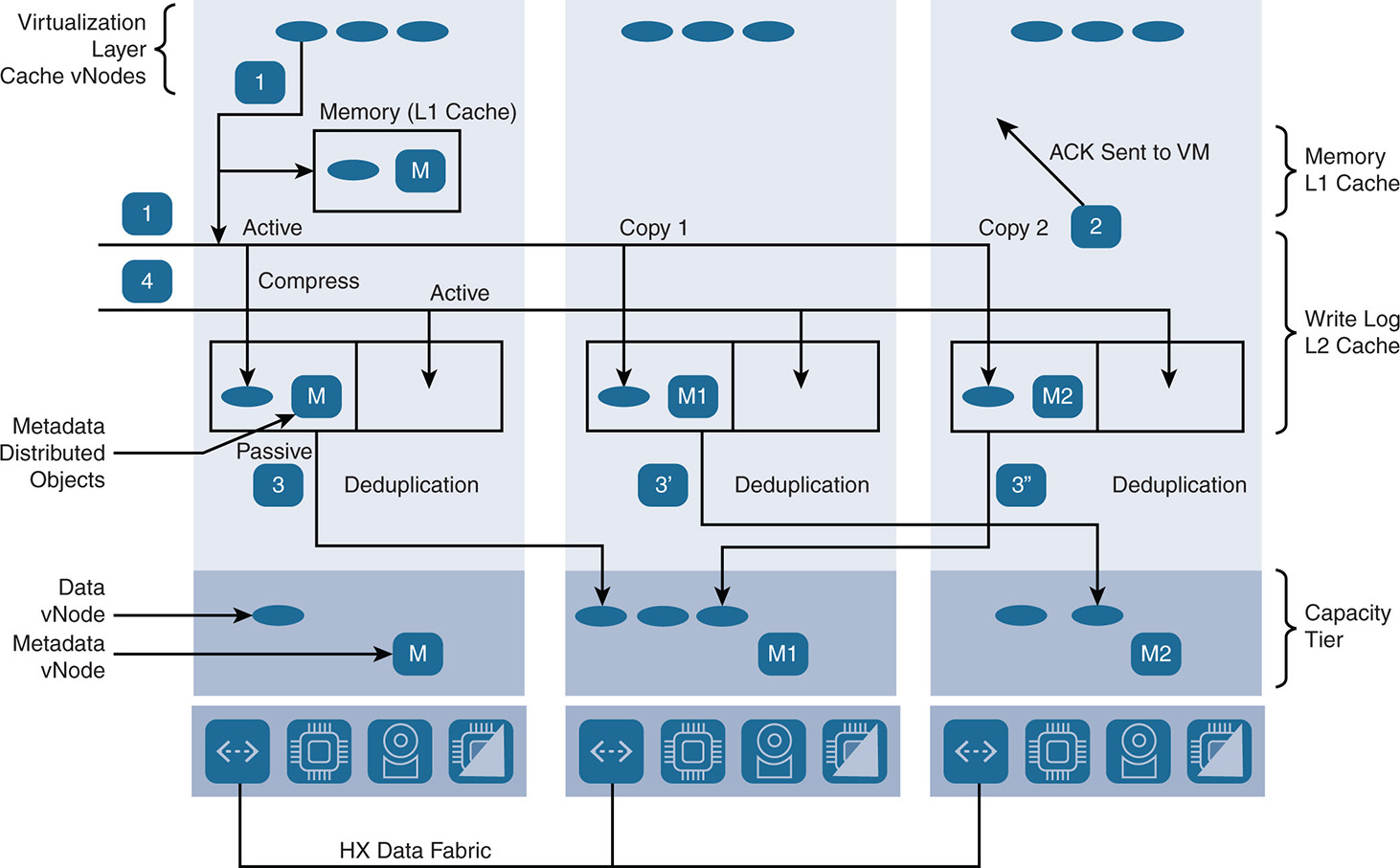
Also, depending on the replication factor, a fork makes a simultaneous copy of the stripes to the write log SSDs of other nodes. HX leverages the IOVisor to do the initial write and the replication. The write operation is not acknowledged until all replicas are written to cache. This ensures data integrity in case of a node or disk failure that might occur during the write operation. At the same time, a copy of the data is also put in the memory cache (L1 cache). This is seen in Figure 9-16. The data remains in the cache tier and is not destaged—that is, moved into the capacity tier—as long as it is current, not updated, and not old. When it is writing the data into the write log, the data is compressed but is not deduplicated at this stage. Compression at this level allows more data to be placed in the cache and enhances performance. HX uses the Google Snappy compression algorithm, which is optimized for speed.
In a hybrid node, a portion of the caching SSD is allocated to the write log and the remaining portion is the L2 read cache. In the case of an all-flash node, the full SSD or NVMe is dedicated for the write log because the reads do not need their own L2 read cache. The write log for both hybrid and all-flash is also available in the memory area of the controller VM. The write log and read cache are all based on a log-structured file system (LFS).
The write log is divided into two partitions whose state changes between Active and Passive, depending on writing into the cache or destaging from the cache. Other than the primary partitions, two sets of partitions are available in the write log to accommodate two more copies of other mirrored stripe units. HX uses an 8 GB or 32 GB write log for hybrid nodes and a 60 GB write log for all-flash nodes. In the case of a hybrid node, the remainder of the cache SSD is used for the read cache.
Note that the size of the write log is not really a big issue as long as the data is destaged fast enough into the capacity tier, as shown in Figure 9-16. The faster the data is destaged, the faster the write log empties and goes back to active. Having very large write logs might affect performance because it takes a long time for the data to be flushed from the cache into the capacity tier.
Figure 9-16 Write Operation in Cache and Capacity
When the VM is writing to a cache vNode, the data goes into the active partition of the primary unit and then is replicated into the active mirrored partitions. When the write into the partitions is complete, an acknowledgment is sent back to the VM. At this point the data is still not deduplicated inside the cache. The size of the write depends on the block size advertised by the NFS or SMB datastore. For example, if a 64 KB block is advertised, the guest OS inside the VM does the writes in 64 KB, and these 64 KB blocks are written in the active partition of the write log.
HX also keeps a layer that sits on top of the LFS and maintains distributed objects, which are the metadata. The metadata keeps track of the data itself and its location. The metadata is first kept in cache and then written to the capacity tier. The distributed objects layer also keeps track of the deduplication and compression ratios plus other information relevant to the objects.
Here are the steps when writing into the write log, as seen in Figure 9-16:
The status of both partitions is Active-Active. Data for cache vNode is written into the first active write log partition of the SSD cache and is written at the same time in the memory cache of the node. Depending on replication, data is copied into the active write log partitions of other nodes.
2. When the replicas are done, an acknowledgment is sent to the VM indicating that the write is done.
3. If the first active partition fills up or the memory cache fills up, the data must be destaged. The state of the first active partition is switched to passive, and the data starts getting destaged to the capacity tier. The destaging in all nodes does not have to happen at the same time. Each node destages whenever its own memory or active write log fills up. During destaging, data is deduplicated. For hybrid nodes, recently written data is copied into the L2 read cache.
New data coming into the cache gets written into the second active partition and replicated into other nodes. When the second active partition gets full or memory cache gets full, the state of the second partition is set to Passive, data gets destaged, and the first partition is set to Active to accept data, and the cycle continues.
Destaging and Data Optimization
Now that the active part of the write log is filled, or the memory consumption in the cache in relation to the write log hits its limit and gets full, the data is ready for active destaging and is moved into the capacity tier (step 3). During the destaging process, in hybrid nodes the recent writes are added to the read cache area (L2 cache) of the SSD cache. This speeds up processing read requests for data that was already written and is still being accessed.
The capacity tier is also based on an LFS. The log segments are called data vNodes and metadata vNodes. The metadata vNodes represent the distributed objects layer that keeps track of the object and help determine whether deduplication and compression must be applied.
The data vNodes can span one host or multiple hosts. This is done to make sure that capacity across the cluster is leveraged because storage in some nodes could be full while storage in other nodes is empty. This also enables the system to do faster rebuilds when a disk fails because the data vNodes can be collected from all over the cluster.
When data is written to the capacity tier, it is replicated into multiple mirrored copies depending on the policy, exactly as was done in the caching tier. The metadata itself is also written to both the caching and capacity tiers and maintains the information about the data and how it is indexed. When data is written to the capacity tier, it is also checksummed to maintain data integrity.
When data is moved into the capacity tier, it goes through inline deduplication. As already mentioned, deduplication is not done on the write log but only while data is moved into the capacity tier after an acknowledgment is received that the data and its copies were written to cache. Data is written to the capacity tier in blocks of 4 KB or 8 KB, depending on the configuration of the block size of the object, so deduplication and compression are always done on fixed blocks.
The deduplication is based on fingerprints of the data block, meaning each data block has a unique fingerprint that distinguishes it from other data blocks. If two blocks have the same fingerprint, the data is not written again. Not all data blocks are indexed because this process uses too much memory. HX does indexing based on frequency of hits, so the more the data is active and is being read or written, the better likelihood that it is indexed.
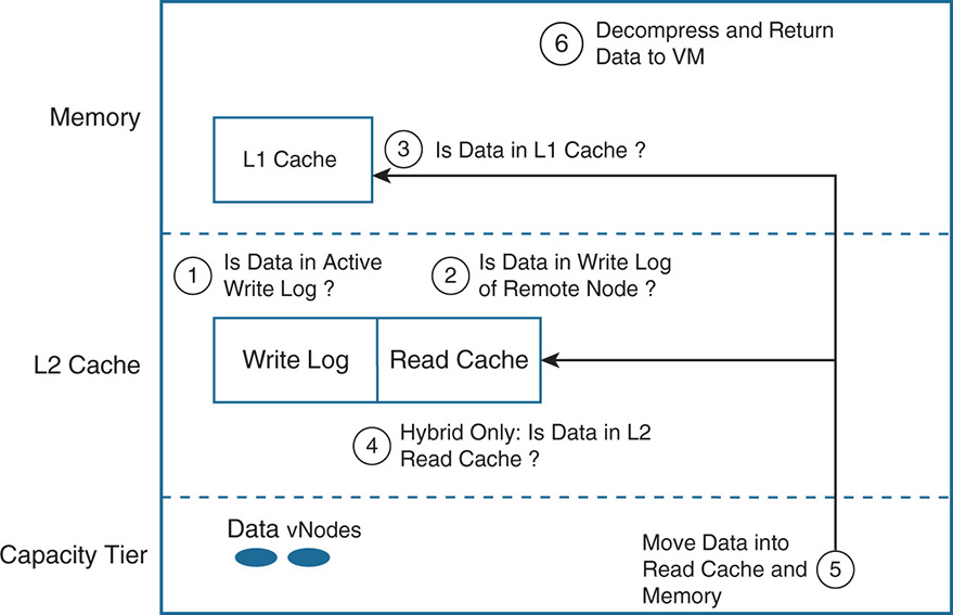
The Lifecycle of a Read Operation
Reading I/O is done differently for hybrid and all-flash nodes. Hybrid nodes read from the read cache area of the SSD cache (L2 cache), whereas for all-flash nodes there is no L2 cache. All-flash nodes read directly from the SSD capacity pool. When doing a read, the IOVisor knows which node has the primary copy of the block. In all-flash nodes, the read always tries to get the primary block. In hybrid nodes, it is possible to request the primary block or any of the copies, depending on which operation is faster. The lifecycle of a read is shown in Figure 9-17.
For data that was recently written and not destaged yet, the data may be found in the active write log of the SSD cache.
If the data is not in the active write log, check the metadata to see whether the data is in the active write log of remote nodes.
Check the L1 memory cache.
Check the L2 read cache of the local node (for hybrid).
It is interesting to note that each node keeps an index cache not only for its own cache but also the full cache of all nodes. This enhances the performance in doing lookups for data blocks across the whole cluster.
If all of these searches cause a miss and still the data is not found, the last resort is the capacity tier. The data is then put in the L1 memory cache and the L2 read cache (in case of hybrid).
After that, the data is decompressed and sent to the VM.
Information about the data blocks, such as whether the data block is compressed, is found in the metadata, that is, the distributed objects. Also, because the identification of the data is done based on fingerprints, the fingerprints are kept in the SSD cache and memory cache. If a data block is already in the cache and another data block is read and found to have the same fingerprint, it is not moved into the cache because it already exists.
Advanced Data Services
HX supports inline deduplication and compression, native snapshots and clones, native replication for backup and disaster recovery (DR), as well as integration with third-party software backup vendors.
Deduplication and Compression
Previous sections that discussed the read and write operation inside the HX system examined how deduplication and compression are applied. It is worth noting here that inline deduplication and compression inside HX are always on and are part of the architecture. The advantage of HX compared to other vendors is that this functionality is done without any performance hits to the system. The fact that this functionality is inline ensures that storage efficiencies occur from the start and before the data goes into the capacity tier. Placing data into the capacity tier without deduplication and then doing this function offline increases storage need by two to three times depending on the replication factor. Even if the data is deduplicated later at rest, the storage requirement has already been increased.
Cisco did not implement erasure coding (EC) in the early HX releases because the embedded inline deduplication and compression minimize the need for such functionality. Bear in mind that the benefits of EC could be outweighed by the performance hit to the system in reconstructing the data using parity information. However, EC is on the HX roadmap.
Snapshots
As discussed previously in this book, snapshots are a way to take a point-in-time snapshot of a VM and its data. The snapshots are used for restoring the state of a VM at a particular point in time in case of a problem and are used to enhance backup and disaster recovery mechanisms. HX has multiple types of snapshots for different use cases:
- Native Snapshots: These snapshots capture the states of working VMs. In case of problems, the VMs can be reverted back to a known state.
- Replication Snapshots: These snapshots are used for data protection. At a scheduled point in time, a snapshot is taken from a running VM. The snapshot is then copied to a remote cluster that is used for disaster recovery. These types of snapshots are internal to the system and are not seen by the user; therefore, they cannot be used to recover the state of a VM in the local cluster.
- Recovery Test Snapshots: These temporary snapshots are used to verify that the recovery system is working.
- Recovery VMs: These restored VMs are created by restoring the most recent replication snapshot from the recovery cluster.
- ReadyClones: These are copies of existing VMs that created a separate guest VM.
In hyperconverged environments, creating snapshots and clones is a straightforward task, depending on the flexibility of the architecture. For VM recovery in the local cluster, HX uses native snapshots that are taken via the HX data distributed system rather than the VMware redo-log snapshots. If ESXi is used as a hypervisor, the first snapshot taken should be a “native” snapshot. This is done through the Cisco HX Data Platform menu inside the vSphere web client and not via the vSphere client snapshot menu. This first native snapshot is called Sentinel. It makes sure that the first snapshot is a native snapshot and not done via VMware redo-log. From then on, any further snapshots can be taken from any snapshot menu and are also native snapshots, which dramatically improves the performance of the snapshot process.
HX uses the Redirect on Write method of doing snapshots; this method was described in Chapter 2, “Storage Networks: Existing Designs,” where its advantages were compared to traditional Copy on Write methods. HX uses a metadata approach to snapshots, by doing zero copying of the actual data. This approach facilitates backup operations and remote replication, which are crucial for enterprises that require always-on data availability. A snapshot is done by keeping pointers to the data. For fast snapshot updates, when modified data is contained in a snapshot, it is written to a new location, and the metadata is updated without the need for read-modify-write operations.
All of the information about pointers and locations of the snapshot is kept via metadata in the cache until the data is destaged. After that, simple metadata is kept in the capacity drive to reference changes in data. The snapshots can be done at the VM level or at the VMware folder level (VMware folders allow a task—restart, for example—to be done on a group of VMs) or for a group of VMs and are easy to add or delete. Deleting a snapshot only requires deleting the metadata in cache without having to do any disk consolidation because the data itself is not copied to start with. This eliminates the need for a long consolidation process as needed by solutions that use delta-disk techniques such as VMware vSAN, which is covered in Chapter 12, “VMware vSAN.”
HX supports snapshot in the ESXi/VAAI environment as well as Hyper-V.
As new software and hardware storage products are introduced into the data center, it is crucial that these products integrate with existing management offerings so that they do not become yet another silo. The HX Data Platform took that aspect into consideration to offer management integration with existing tools such as vSphere vCenter Snapshot Manager. This allows support of a snapshot management functionality such as scheduling the frequency or number of snapshots and retention. This is a value-add for VMware customers who are already familiar with the platform. Any newer functionality such as performance metrics or cluster status is added via plug-ins to the vSphere web client.
Cloning
The HX clones are writeable snapshots. This means that if clones are specified to be created, the snapshot taken at that time is written into the capacity tier at the same time the data writes are taking place. HX uses metadata to create many clones at very high speeds without a CPU hit compared to methods that do full copies. As clones are being created, data is also deduplicated and compressed similar to any write to disk. Space savings are achieved only by keeping track of any changed data while all other data is handled via pointers and metadata to keep track of the pointers. Similar to snapshots, clones integrate with ESXi/VAAI and Hyper-V/ODX. Clones are done at the granularity of a VM, folder level, or a group of VMs. HX offers a tool called ReadyClones that allows fast clone provisioning with a wizard. Hundreds of clones are created by simply using a prefix name, a description of the clones, and the number of clones. The wizard automatically creates the clones starting with the prefix and appending a number that is incremented. Ready clones also provide customization via scripting to allow each clone to obtain its own IP address or other parameters on startup.
Asynchronous Native Replication for DR with Remote Clusters
The HX Data Platform data protection allows for the asynchronous native replication for DR (NRDR) for replicating and protecting VMs between remote clusters. Asynchronous replication can be done at scheduled times and can tolerate some latency on the WAN links because it is not done in real time and does not affect the input/output processing on a running application. To perform data protection, two clusters have to be paired with each other. After that, replication networking is set up by having HX Connect provide IP addresses to be used by the local cluster nodes to replicate to the remote nodes. HX Connect also creates VLANs through UCSM for dedicated replication network use.
After you set up the pairing and network connectivity that is specific for replication, VMs can be replicated at specific intervals that range from 5 minutes to 24 hours to match the selected recovery point objective (RPO). VMs are replicated to the remote cluster by making a copy of the replication snapshot to the remote cluster. In the event of a disaster at the local cluster, the most recent copy of the VM in the remote cluster can be used to recover the VM. VMs are optionally grouped inside protection groups, which assign similar attributes to the protected VMs. Configuration of the time intervals for scheduled replication and monitoring of the replication process in and out of a cluster are done via HX Connect.
Synchronous Native Replication for DR with Stretched Clusters
HX uses synchronous native replication for disaster recovery (NRDR) with stretched clusters. This is normally used for a tier-1 application that cannot afford any data loss and requires a zero recovery point objective. Stretched clusters allow the data center to be stretched between two data centers over a campus or metropolitan area network or WAN for active-active redundancy. Nodes replicate their data in the local and remote data centers. Unlike asynchronous replication, where replication can happen at scheduled times, with synchronous replication, when a write is done local and remote, it must be acknowledged for the I/O operation to be committed. This, of course, adds extra latency to the write operations. Cisco recommends the use of 10 GE links between the sites and that round-trip time (RTT) for a packet not exceed 5 milliseconds. For read operations, the reads are done from the local data center where the application exists and there is no performance impact. Stretched clusters result in zero recovery point objective because the data is always consistent between the two sites. Recovery time objectives (RTOs) could also get near zero with VM HA mechanisms where a VM is copied and synchronized to the second site but remains inactive until the primary VM fails. Figure 9-18 shows an example of a stretched cluster.
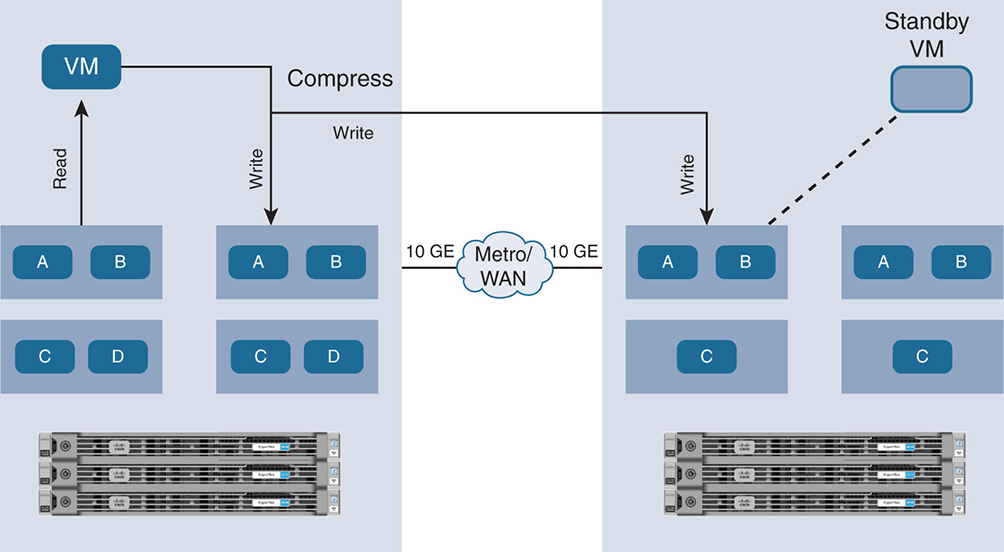
In Figure 9-18, note that the reads are done locally while writes are local and remote. As data is sent over the WAN, it is compressed to efficiently use the WAN bandwidth.
Integration with Third-Party Backup Tools
In addition to synchronous and asynchronous native replication for disaster recovery, HX integrates with third-party backup and recovery tools. HX integrates with enterprise backup software vendors such as VMware, Veeam, Commvault, and Zerto. HX offers APIs to allow third-party vendors to offer their data protection solution through the HX Data Platform. With VMware, for example, HX is managed by vCenter and uses VMware’s data protection and vSphere’s replication with vCenter Site Recovery Manager.
Integrating with third-party vendors through APIs allows for better backup functionality while enhancing performance by utilizing the system’s native replication capabilities. Keep in mind that many HCI vendors also compete in the backup space and secondary storage by enhancing the functionality of their own backup software in support of secondary storage.
Figure 9-19 shows a sample integration between HX and Veeam.
Figure 9-19 HyperFlex Integration with Veeam
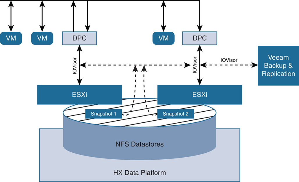
A close integration with Veeam allows for better backup functionality and better performance by having Veeam rely on HX ‘s capabilities in creating and deleting snapshots. Without the integration, Veeam must rely on native VMware’s snapshots. As writes are done, VMware redirects the writes to the Redo-Log snapshot, Veeam reads the data from the Redo-Log, and then snapshots are deleted. This extra layering is inefficient because deleting the snapshot takes a long time. By integrating with HX, Veeam relies on HX to create and delete the native snapshots for more efficiency. As seen in Figure 9-19, Veeam integrates with HX through the IOVisor. Because the IOVisor redirects all I/O from the VMs and does load distribution between all nodes, Veeam reads the native snapshot data from the IOVisor.
In the case of ESXi, the IOVisor presents the storage network to ESXi as NFS datastores. Veeam uses the IOVisor to read the data directly from the HX snapshot, using the NFS HX data network. In addition, Veeam uses the capabilities of VMware’s Changed Block Tracking (CBT) to receive the delta difference between snapshots, so future backups on updated snapshots are done only on the changed data. This improves backup efficiency over WAN links by reducing the amount of data that must be exchanged during the backup.
It is worth noting that many advancements are taking place in backup and restoration for secondary storage. Secondary storage is longer-term storage that is not actively used by the applications. Also, with secondary storage nonzero RPOs and lower service-level agreements (SLAs) can be tolerated. Other than working with established software backup vendors, Cisco has done joint solutions with secondary storage startups, such as running Cohesity hyperconverged secondary storage software on Cisco UCS servers. This gives HX deployments added capabilities in historical tracking of the data, archiving, file versioning, file indexing, advanced file search engines, data analytics on backed-up data, and so on.
HyperFlex Security
HX adopts multiple security mechanisms for securing the data as well as securing access to the platform. These security mechanisms are grouped under the following categories:
- Securing data-at-rest
- Operational security
- Complying with security regulations and certifications
- Management security
Securing Data-at-Rest
HX uses self-encrypting drives (SEDs) to encrypt the data-at-rest inside the physical HDDs or SSDs. This ensures that if drives are taken from the system, data is protected. Because the encryption and decryption are done via the disk hardware itself, no additional load is added to the CPU. Only the key management is done via software. To use data-at-rest security, all disks in all nodes on the cluster must be SEDs.
Each drive comes with a factory-generated data encryption key (DEK). The internal disk circuitry uses this key to encrypt or decrypt the data. However, when the drives are initially installed, they are in an unlocked mode by default, so data can be read. To secure the data, the system must lock the SED and put it in an auto-lock mode. This is done via software, using another key called the key encryption key (KEK). The KEK is externally generated and is passed to the disk via the disk controller. The KEK is used to encrypt or decrypt the DEK (not the data). When the DEK is encrypted, the data cannot be accessed, and when the DEK is decrypted, the data can be accessed. As long as the disk is powered on, the KEK can be sent by the system to the controller to unlock the DEK. However, if the disk is removed from the system and loses power, the disk goes into automatic lock. Without the KEK, the DEK cannot be decrypted, and the data is secure.
The KEK in HX can be generated through three methods: locally generated, remotely generated using a trusted certificate authority, or remotely generated using self-signed certificates.
Locally generated KEK is the simplest method but the least secure. HX uses the Cisco UCSM to generate the KEK from an encryption passphrase. This creates a single KEK that is used by all disks on all nodes of the cluster. This type of key generation can be used in test or proof-of-concept setups but is not secure enough for production environments.
For remote key generation, HX complies with the Key Management Interoperability Protocol (KMIP) 1.1 and works with leading key management solutions such as Gemalto SafeNetKeySecure and Thales Vormetric Data Security Manager. Such products are offered via physical appliance or virtual appliances and offer, among other functionality, centralizing the administration of the encryption policies and keys. Such solutions also provide reporting, auditing, and compliance tracking.
When getting a key remotely, the UCSM uses KMIP to retrieve the key from a Key Management Server (KMS). The client/server communication between the UCSM and the KMS is secured using trusted certificate authority (CA) signed keys created from certificate signing requests (CSR). The second method is for client/server communication between the UCSM and KMS to be done via self-signed certificates. In both cases, remote key configurations create a separate KEK for each node and can be used for all disks in that node.
In support of key management, HX is managed by an HTML5 Cisco Connect interface that facilitates the configuration, enabling rekeying and erasing data on the SEDs inside the HX cluster. Cisco Connect controls the workflow and offers a certificate-based chain of trust between the HX Data Platform and the KMS.
Operational Security
Having a consistent operational model in delivering security is important. When dealing with policies and key management among hundreds of nodes and servers, it is crucial that a systematic and consistent approach be adopted that requires a level of automation across all nodes. The UCSM, which runs inside the fabric interconnect, adopts a set of service profiles and templates that define all the characteristics of the HX nodes in software. These profiles define all server characteristics such as network interface cards, adapters, and firmware; they allow a uniform configuration across the HX cluster. The Cisco UCSM specifies the HX Data Platform security policies and the key management software. By defining such interaction within service profiles, the operator is assured of consistent security behavior across the whole data center.
Complying with Security Regulations and Certifications
Cisco HX with the use of SEDs complies with a number of security regulations, such as the Health Insurance Portability and Accountability Act (HIPAA), Payment Card Industry Data Security Standard (PCI-DSS), Federal Information Security Management Act (FISMA), General Data Protection Regulation (GDPR), and Sarbanes-Oxley Act.
The key management solutions that HX works with are validated for Federal Information Processing Standard (FIPS) 140-2, which is a government publication by the National Institute of Standards and Technology (NIST) for “approving cryptographic modules” for transferring sensitive information.
Cisco HX has completed Common Criteria certification for Evaluation Assurance Level (EAL) 2 for Information Technology Security Evaluation Criteria (ITSEC). HX certification activities are ongoing for future releases. The ITSEC is an international standard certification that ensures that the security features of a product are properly implemented. EAL numbering is between 1 and 7. A product with higher-level EAL does not mean that the product is more secure than others; it just indicates the level of documentation and testing to certify the security functions.
Cisco HX also implements the Secure Technical Implementation Guide (STIG) for hardening the product against security attacks using best practices. An example is an implementation of the ESXi Server security recommendations, which is done via automation scripts for setting STIG parameters.
Management Security
HX uses many management tools to ensure the security of the product. The Cisco HX Connect HTML5 interface manages the whole cluster operation and the lifecycle of the data-at-rest encryption. The UCSM and the service profiles ensure consistent security policies across all nodes. In addition, Cisco HX uses authentication and authorization mechanisms integrated with vSphere single sign-on (SSO), Microsoft Active Directory, and Lightweight Directory Access Protocol (LDAP). The SSO, for example, deals with the identity management of the users and applications that interact with the vSphere platform. SSO is an authentication service in which clients send authentication messages to a Security Token Service (STS), which checks the user credentials and, if validated, generates a token. The user or application uses that token to access resources. vCenter uses the token to perform vSphere operations on behalf of the client. SSO is not a replacement for Active Directory or LDAP but rather complements them by doing single token authentication on the identity.
HyperFlex also uses role-based access control (RBAC) to specify the role of a user or administrator and their access privileges for doing configuration or for monitoring the system. All transactions to the system through the command-line interface (CLI), APIs, or Connect UI are monitored and tracked to identify the source of any operation.
Looking Ahead
This chapter covered the details of the HX HCI implementation. The integration of HX with UCS is a major differentiator between Cisco and other vendors. The adoption of the widely adopted UCS service profiles turns the whole compute system into reusable software modules. The integration with legacy SANs and converged systems via fibre channel and iSCSI will facilitate the migration of data from older systems to the new hyperconverged environment.
Also, the way Cisco differentiates from other vendors is a suite of tools and software products to allow better management, provisioning, monitoring, and automation for HCI deployments.
Chapter 10, “Deploying, Provisioning, and Managing HyperFlex,” covers the deployment provisioning and management of the HX platform. This includes references to tools to help with sizing the platform depending on the workload. The tools also help in managing all aspects of deploying and monitoring the data services from inside the private data center. Other products such as Cisco Intersight help in the provisioning and management of the platform from the public cloud.
Chapter 11, “HyperFlex Workload Optimization and Efficiency,” discusses methods for workload optimization via the Cisco Workload Optimization Manager and Cisco Tetration for traffic visibility at the flow level. Also, with the introduction of Cisco AppDynamics, Cisco delivers advanced workload optimization and troubleshooting by tracking the performance of each application, analyzing the root cause of any performance issues, and tracking the business impacts on end users.
References
[1] https://www.cisco.com/c/en/us/products/hyperconverged-infrastructure/hyperflex-hx-series/index.html
[2] https://www.cisco.com/c/en/us/products/servers-unified-computing/ucs-6300-series-fabric-interconnects/index.html
[3] https://www.cisco.com/c/en/us/products/servers-unified-computing/ucs-c-series-rack-servers/index.html
[4] https://www.cisco.com/c/en/us/products/interfaces-modules/unified-computing-system-adapters/index.html
[5] https://www.cisco.com/c/en/us/products/servers-unified-computing/ucs-b-series-blade-servers/index.html
[6] http://www.esg-global.com/cisco-hyperflex
[7] https://www.cisco.com/c/en/us/td/docs/unified_computing/ucs/UCS_CVDs/HX171_VSI_ESXi6U2.html