
Chapter 7. HCI Functionality
This chapter covers the following key topics:
 Distributed DAS Architecture: A description of HCIs physical and logical distributed architecture, including direct-attached storage (DAS) and the distributed data controllers. The chapter describes high-level HCI functionality such as scale-out architecture, performance, data protection, and hardware resiliency. You will see discussions about the file system, provisioning model, hardware assist, networking policies, and automation.
- Advanced Data Storage Functionality: A description of the different HCI data storage functionalities such as deduplication and compression, erasure coding, replication, backup, and disaster recovery. Security issues and the provisioning, management, and monitoring of HCI systems are also discussed.
Although this book attempts to be vendor agnostic, it becomes difficult to explain terminology that is created by marketing rather than engineering. If hyperconvergence came out of the Internet Engineering Task Force (IETF), it would have been a lot easier to explain how it works and where it is applied. Hyperconvergence and hyperconverged infrastructure are marketing terms that are being used as a catch-all. One thing is for sure: hyper comes from hypervisor, and converged comes from data center convergence. Therefore, the presence of the hypervisor is key to achieving hyperconvergence from a software level, but as you will see in the implementations, it might also become the bottleneck and a hindrance to performance. From a software perspective, software-defined storage (SDS) plays a main role in hyperconvergence because it defines distributed file systems capable of aggregating all storage under one pool.
From a hardware point of view, if you were to say that hyperconverged architecture means that storage and compute and networking are combined in a single system, you would be 80% accurate. Still, you will see architectures in which the networking is missing claim hyperconvergence, and others in which both networking and compute are missing and claim hyperconvergence.
Distributed DAS Architecture
Hyperconverged infrastructure (HCI) moves away from the traditional centralized storage area network (SAN) and network-attached storage (NAS) to a distributed direct-attached storage (DAS) architecture. It is interesting that the industry traveled full circle from DAS to SAN and back to DAS. The reasons that DAS is back are many:
- The compute power inside servers is now more powerful than any traditional storage array. It is true that storage arrays can now adopt faster central processing units (CPUs); but in a centralized storage model, the CPU still has to attend to hundreds of disks. In an HCI model, processing is distributed over many hosts, with each host having CPU power that could exceed the CPU power of a single storage array. HCI implementations use standard x86 CPU architectures that provide openness and cost savings compared to traditional closed systems.
- The price of disks, whether hard disk drive (HDD) or solid-state drive (SSD), also came down to the point where placing powerful Serial Attached Small Computer System Interface (SAS) or flash disks inside servers is not that expensive. One of the arguments of centralized architectures is that consolidating the functions in a central pool of flash disks is much less expensive than spreading disks over many servers. This argument holds true if each server works independently of the others and overprovisioning takes place on each server, but this is not true with HCI. Because HCI treats all storage as a single pool and uses policy-based storage that is application aware, the efficiency of using the storage even if it is distributed is extremely high.
- The Gigabit Networking speeds moving up to 40 GE and 100 GE are minimizing network latencies, making the convergence between storage networking and data networking viable. As such, combining compute, storage, and networking in the same system or cluster of nodes is the strong point for hyperconvergence.
Figure 7-1 shows how nodes are physically connected in an HCI cluster.
Figure 7-1 Hyperconverged Infrastructure—Physical View
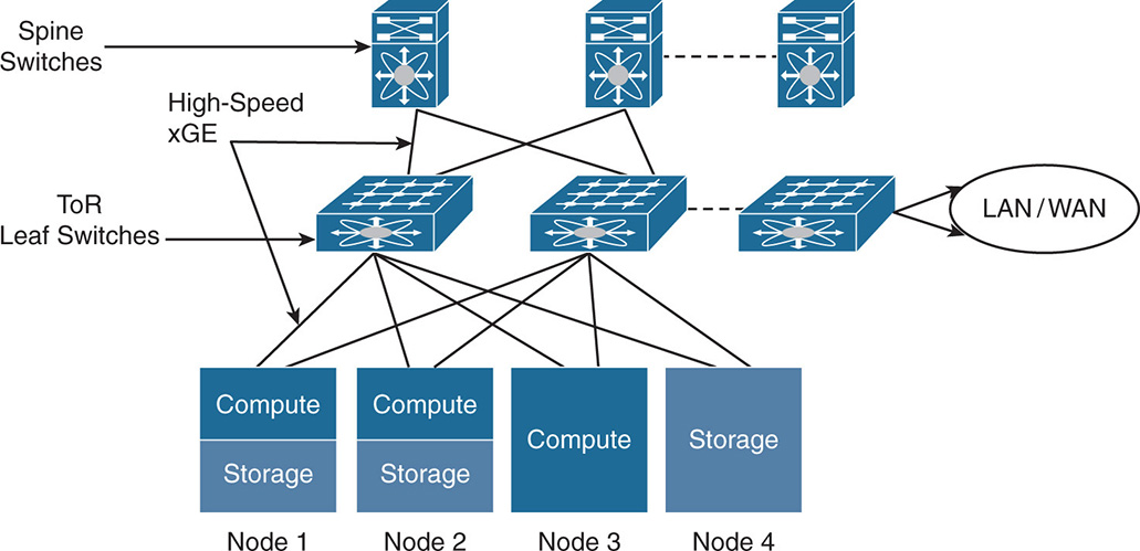
Note that you moved into a distributed DAS and eliminated SAN and NAS. Nodes or hosts can be compute only, storage only, or compute + storage. This depends on the vendor implementation and whether the nodes/hosts are appliance-based or off-the-shelf servers. The connectivity between the nodes is done via high-speed Gigabit Ethernet interfaces. Smaller remote office implementations work well with 1 GE interconnect, whereas midsize and large implementations with lots of input/output (I/O) requirements are better served with 10 GE, 40 GE, and eventually 100 GE interconnects.
Normally, each node has two network interfaces that are dual homed to two top-of-rack (ToR) switches for redundancy. The ToR switches are called the leaf switches and are connected to each other via spine switches. The leaf and the spine switches grow as needed to accommodate more nodes in a cluster. The leaf switches form the edge of the network that connects to other data centers or the Internet over the campus or WAN connection.
Distributed Controllers
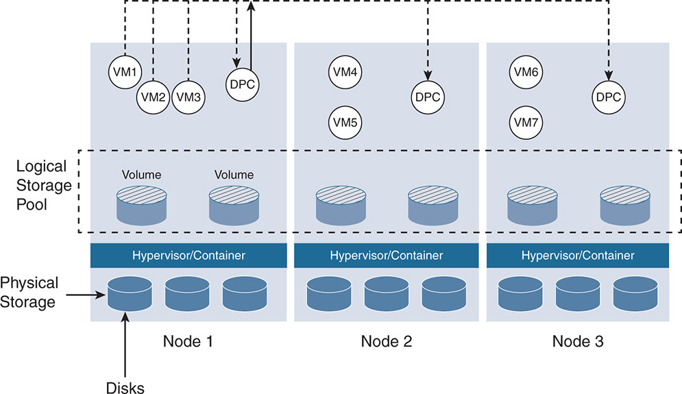
Hyperconverged architectures use a distributed controller model. Unlike storage arrays, where a pair of storage controllers controlled the I/O on disks, HCI has software controllers distributed across nodes. The naming of the software controllers differs between vendors. Some call it virtual storage appliance (VSA), others call it control VM (CVM), still others call it data platform controller (DPC), and so on. For consistency, let’s call these software modules data platform controllers. The DPC is part of an SDS architecture that allows all nodes to participate in the I/O processing. The DPC runs as a virtual machine that communicates with the hypervisor or a container environment and makes all storage available on all nodes look like one central pool of resources that any virtual machine (VM) or container can use. Figure 7-2 shows the DPCs on each node. The DPCs communicate with one another to create the logical storage pool and work in parallel to perform the storage data service’s functionality.
Scale-Out Architecture
The scaling of any architecture can be measured in its ability to scale out and scale up. Scaling up is when performance of a node is increased by boosting the compute and storage of the node itself. This is what you are used to with storage arrays; when an array runs out of steam, it is replaced with a bigger node that has more CPUs, memory, and storage.
In contrast, because HCI is a distributed architecture based on the concept of scaling by adding nodes, HCI is by design a scale-out architecture. The more nodes you add, the more CPU, memory, and storage I/O you get. The definition of node depends on the vendor implementation. Nodes can be individual off-the-shelf servers or custom-made hardware. Although from a software point of view both approaches deliver similar functionality, from a hardware point of view they are much different. Hardware that is appliance based with preconfigured nodes offers more peace of mind by being more uniform with the ability to apply service profiles on such nodes. Nodes are preconfigured for compute only, storage only, and a combination of compute and storage on the same nodes. All depends on what a particular vendor implements. As VMs or containers are deployed, and if more compute power is needed, more compute nodes can be added. The same goes for storage. If the system has enough compute power but not enough storage, more storage nodes can be added. And the same goes for combination compute plus storage nodes to grow both compute and storage at the same time. This type of granularity is powerful because it uses the hardware more efficiently without big jumps in unused compute or storage capacity. However, with added flavors of nodes comes added complexities. Therefore, some vendors, for example, decided not to build storage-only nodes, and some do not recommend adding compute-only nodes. In any case, because everything is built by the same vendor, there is one vendor to blame in case of any issues.
With implementations that rely on off-the-shelf servers for nodes, you have more flexibility to scale up by adding more storage or more memory to an individual node. However, with such flexibility comes the nightmare of balancing the different nodes in a cluster because most HCI vendors recommend that the nodes in a cluster are uniform, which means that the compute and the number of drives of the nodes in a cluster be somehow equivalent. Also, you need to do node customization, making sure that all components including server, HDD, SSD, network interface card (NIC), host bus adapter (HBA), and other components are certified for the HCI software vendor.
HCI implementations differentiate in their ability to make the process of adding storage and compute, as required by the application, as automated and as simple as possible.
HCI Performance
HCI promises increased performance in a higher number of input/output operations per second (IOPS) and lower latency in I/O operations. This is mainly attributed to HCI being a distributed system, in which multiple nodes work in parallel on reading and writing the I/O. In storage arrays, centralized controllers used to handle the I/O of the whole data center. Compare this to tens and hundreds of nodes, with each having powerful CPUs and memory sharing the I/O load. The bulk of the distributed systems reaches much higher performance than the handful of centralized arrays.
Another factor that affects performance is the proximity of data to the application. This is an area of debate in the industry because the distributed nature of hyperconvergence could result in having the data scattered over many nodes. Therefore, I/O has to cross the network as well. In traditional storage arrays, the application runs on the host, whereas the data is centralized somewhere in the network. This means that every I/O exchange between the VM and storage has to cross the network every time. With hyperconverged architectures, each node can utilize its cache to accelerate the I/O handling and could benefit from the fact that the data could be local. However, even if the data is distributed among many nodes, the fact that each node can participate in the I/O processing through the local controller greatly increases performance.
In principle, an HCI system centered on applications and their needs outperforms storage array systems that have no application visibility and are centered on disks.
All HCI vendors claim that they have the highest performance, but the reality is that some systems outperform others due to differences in software architectures and whether the software is designed from the ground up for HCI or is adapted for HCI. As HCI implementations were developed in the past few years, each emerged from different starting points. Some architectures were home grown as extensions of already built hypervisors. Some were built based on open source software for both hypervisor and SDS. And some were built from scratch and with distributed architectures and virtualization in mind. Although some implementations are 100% done in software, others try to leverage hardware acceleration to offload the CPU.
Measuring performance is tricky. To be fair to vendors, you should compare apples to apples. You should weigh performance with functionality. A cluster that is just doing compute and I/O reads/writes should not be compared to a cluster performing advanced functionality. Also, two HCI implementations that deliver similar performance should be benchmarked on whether they are using comparable compute and storage resources.
Resiliency Against Hardware Failures via Replication
Traditional storage arrays came in redundant configurations. Redundant storage controllers, redundant fabric switches, redundant HBAs, and multiple paths from any server to any storage are deployed. On the other hand, HCI is built on a distributed architecture and grows one node at a time. It is important that HCI offers the same level of resiliency as legacy storage. Protection needs to be done at the node level, at the network level, and at the virtual disk level. When a node fails, the disks attached to that node are no longer in the pool. HCI must ensure that the data is reconstructed and assigned back to the application. Some applications require high availability, where the application moves from a failed node to a working node with some level of disruption. Other applications require fault tolerance, where the application has zero downtime, so upon node failure, the application should continue working on other nodes with zero impact to the end user.
This is when replication becomes the cornerstone of HCI. Most HCI implementations use replication to distribute the data over multiple disks, whether in the same node or in different nodes inside a cluster as well as outside a cluster. Replication makes sure that the data is spread across many hardware entities such that if an entity fails, the data can be recovered. This is seen in Figure 7-3.
Figure 7-3 Data Protection via Replication
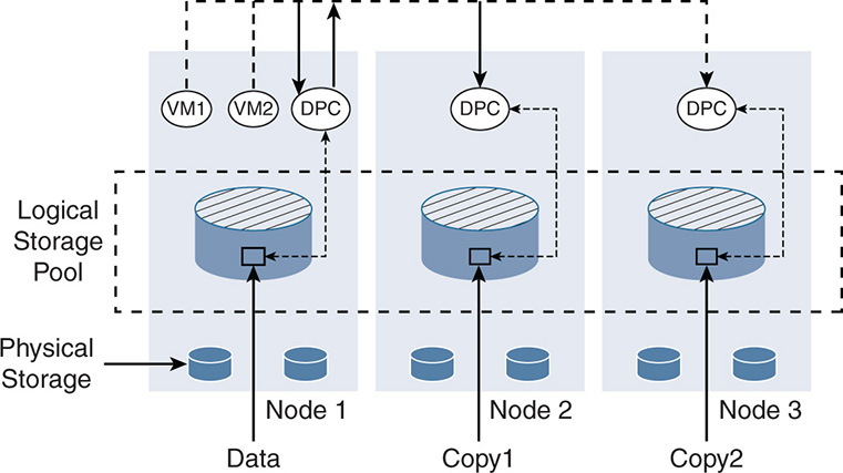
Notice that the data on Node 1 was replicated by the DPCs to Nodes 2 and 3. If Node 1 fails, for example, VMs 1 and 2 can be moved to Nodes 2 and 3, and the data will still be available. Note that the data is not necessarily a full virtual disk. The data could be a stripe of a virtual disk depending on the striping technique the vendor uses. The point is that a specific piece of data can be reconstructed upon a failure.
Protection via replication at some point becomes expensive and causes performance issues. IT administrators must decide whether to protect against a single failure or multiple failures. The good news is that such policies can be done at the granularity of a virtual machine or container. Some critical VMs and applications might need data protection against two failures, whereas other applications might need to be protected against a single failure. The more data is replicated, the more resources such as CPU, memory, and storage are used.
HCI systems differentiate in how they implement storage space reduction and protection via mechanisms such as deduplication, compression, and erasure coding and how well these functions are done without performance degradation.
File Systems
Chapter 2, “Storage Networks: Existing Designs,” discussed the different types of storage, such as block-level, file-level, and object-based storage. Different HCI vendors use different file systems depending on the architecture. The choice of file system is important because it dramatically affects the performance upon doing I/O reads and writes. One file system that stands out as being one of the best used for HDDs and SSDs is a log-structured file system (LFS). LFS enhances the performance of reads and writes and minimizes the problems already discussed with flash, such as wear upon writes. LFS is used in some leading HCI architectures, such as with Cisco’s HyperFlex. The next section provides a brief description of an LFS.
A log-structured file system (LFS) allows flexibility for the compute layer to access data as files, objects, or blocks. With traditional file systems, data is put anywhere on the disk. This creates disk fragmentation, causing performance issues for data reads and writes. The LFS solves performance issues for both HDDs and SSDs.
HDDs experience the best read and write performance when the data is sequential; the head of a magnetic disk does not have to jump around between random blocks to write or collect the data. For SSDs, erasing blocks dramatically shortens the life and performance of the drive because of flash wear. The log file structure solves these problems by always doing sequential writes and by not erasing stale or old blocks. This is explained next.
The log-structured file system is a “log” in the form of a circular buffer. When data is written, it is appended at the end of the log. Whenever a new block of data is added to the same object or file, the new data is appended to the log without modifying the older data. However, a new index is appended that references all blocks of the same object or file. This is illustrated in Figure 7-4.
Figure 7-4 Log-Structured File System
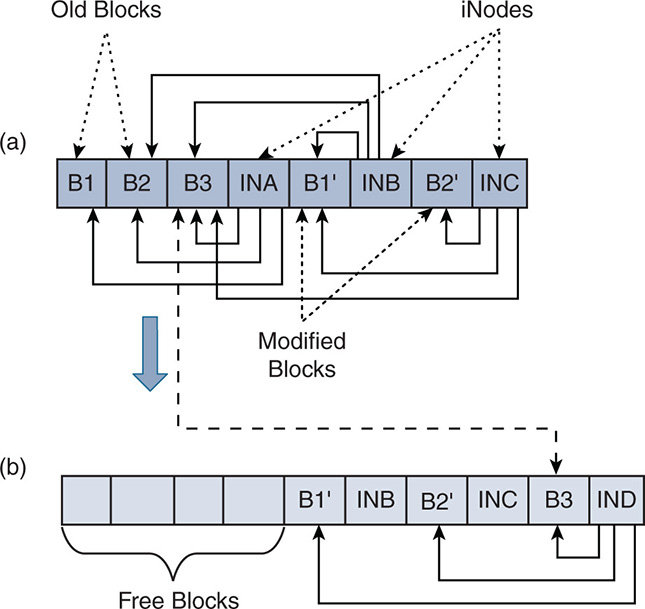
Figure 7-4a shows that an object consists of a set of blocks: B1, B2, B3, and so on. These blocks are written sequentially, where each block is appended to the end of the log. An index called iNode is used as a set of pointers to the locations of the blocks in the same object. In this example, iNode A (INA) references the original blocks B1, B2, and B3.
Assume now that block B1 changed to B1’. Instead of erasing B1, a new block B1’ is written at the end of the log, and a new iNode B (INB) is written. INB now references B1’, B2, and B3.
Now assume that B2 is updated to B2’. The same process occurs because B2 is left untouched; the updated B2’ is written sequentially to the log, and a new iNode C (INC) is written pointing to B1’, B2’, and B3.
As you see, you can get to the point that you have stale information that needs to be removed. Blocks B2 and B3 are not needed, and iNodes INA and INB are not needed. However, freeing these empty blocks causes disk fragmentation, which causes performance issues. Also, erasing these blocks is not good for flash SSDs.
In a typical file system, you must go into a big process of garbage collection and defragmentation. However, in a log-structured file system, there is more flexibility. The space can be divided into chunks of storage, and the cleanup of all data can be done within a chunk as needed. In this example, and as seen in Figure 7-4b, block B3 can be relocated to the end of the log, which frees up a series of continuous empty blocks from B1 to INA. The log-structured file system can keep relocating some blocks as needed to free up space without major performance hits. Once the end of the disk is reached, the process can continue at the beginning of the disk in a circular fashion.
Change in the Provisioning Model
HCI offers a different provisioning model than legacy storage arrays, a model that is top-down rather than bottom-up. With the legacy model, the storage administrator for a particular storage vendor starts by provisioning capacity logical unit numbers (LUNs). The LUNs are given a set of capabilities, such as whether the LUN needs to be replicated or not, protected or not. Zoning and masking are also configured per LUN.
Overprovisioning is the norm to ensure that an application always has enough capacity. Because storage has no knowledge of the application, when a virtualization administrator creates a VM, a request is sent to the storage administrator with the specific requirements. The storage administrator in turn tries to match the requirements with the available LUNs and capabilities or create entirely new LUNs. After that, the storage administrator specifies a datastore to be used. This provisioning model normally results in hundreds of datastores and islands of unallocated storage. Storage administrators spend most of their time migrating data and creating LUNs, while virtualization administrators wait until storage is provisioned. It could be a week or more of back-and-forth negotiation between the two departments before the storage is allocated.
The HCI model is top-down and is application centric when it comes to specifying storage policies. With HCI, the distributed file system creates a shared pool of storage resources from the different physical nodes. Upon creating a virtual machine, a user indicates the storage policies needed by the application. As such, the VM data is placed in the storage pool in a manner that satisfies the policies the application needs. The HCI model is extremely efficient and does not leave wasted resources because it can be implemented at the virtual machine level and instantaneously leverages resources from a dynamic pool, as data services are set per virtual machine.
Hardware Acceleration
Hardware acceleration will prove to be a key element in differentiating between HCI implementations moving forward. Although HCI is software defined, software on its own will run out of steam. Hardware assist becomes crucial when dealing with advanced functionality that is CPU intensive. Many HCI vendors are betting on host CPUs to deal with most of the storage I/O functions. This should remind you of the early stages of networking, where the control path that handles routing protocols, as well as the data path that handles traffic forwarding and policies such as access lists and firewalls, was all done in the CPU. You know how long that lasted until the routers started melting down and becoming bottlenecks. It seems that this is moving along the same path now, but with the added advantage that CPUs are much more powerful, and the distributed node architecture can divide the load between the CPUs.
However, HCI implementations that are architected to be 100% tied to CPUs will eventually struggle and take many iterations before moving toward hardware acceleration. To give an example, hypervisors such as VMware ESXi are becoming a catch-all for functionality. If you dig deeper, you will find that VMware’s networking functionality such as NSX, which includes switching, tagging, encapsulation, routing, and tunneling, is part of the hypervisor. VMware’s HCI implementation vSAN is also bundled with the hypervisor. Advanced functionality such as deduplication and compression are part of the hypervisor, too. Not to pick on VMware, because this book is intended to be vendor neutral, but such architectures will eventually break unless they are rearchitected to offload some of the software functions to hardware acceleration.
SDS allowed us to decouple the storage functionality from hardware in such a way that vendors now develop storage policies independent of the hardware and move away from hardware-closed systems. However, there is now a risk of moving in the direction of software-closed systems, where even if you run the software on commodity hardware, you cannot decouple functionality from the hypervisor to take advantage of the hardware. Cost savings is achieved, but it could be at the expense of performance.
Networking Integration
HCI is supposed to combine compute, storage, and networking in a single system. With HCI, the fibre channel storage networking disappears. As you recall, the SAN consisted of HBAs connected to fibre channel switches to form redundant fabrics. The redundant fabric in turn connected to redundant storage arrays. Masking and zoning were used to segment the network logically, and mechanisms such as multipath were used to access the storage. Links worked in active-active or active-passive modes to fully leverage the network capacity as much as possible while offering fault tolerance in case of network component failure.
HCI eliminates the SAN, as nodes individually connect to ToR switches. Instead of having one HBA for storage and one NIC for data connectivity, the servers now have one converged NIC that handles storage and data networking over a fast GE network. Compute/storage nodes talk to each other over a high-speed 10 GE, 25 GE, 40 GE, 50 GE, or eventually a 100 GE network.
Most HCI vendors downplay the networking part. First implementations of hyperconvergence focused mainly on the SDS and left out the storage-defined networking (SDN). Because the claim to fame of hyperconvergence is faster rollouts and ease of provisioning and automation, vendors who do not focus on the networking piece will be at a major disadvantage.
Two areas to watch out for when looking at HCI are networking policies and networking automation. These are discussed briefly in this section and examined in a lot more detail in Part VI of this book.
Networking Policies
One of the main differentiations of HCI from traditional SANs is that HCI is application centric rather than storage centric. You are now taking a top-down approach, and the starting points are the storage needs of the application and the access security rules for the application. HCI allows you to specify per-VM security rules. In a multitier web, app, database three-tier architecture, you can specify how the tiers are accessed among each other or from external entities. You can also decide whether to process security rules at the VM level or redirect these rules to other software or hardware appliances that deliver networking services such as firewalls or load balancers.
Networking Automation
Another essential component of HCI is the ability to automate the IP address assignment and reachability. You can also automate the network connectivity between the HCI nodes within the data center, between data centers, and with the public cloud. Traditionally, this exercise was done via L2 and L3 protocols such as spanning tree, Open Shortest Path First (OSPF), Intermediate System to Intermediate System (IS-IS), Multi-Protocol Border Gateway Protocol (MP-BGP), and other protocols. In addition, VM mobility within the data center to handle better traffic distribution or protection around failure necessitates IP-level mobility, where an application can move around without affecting its connectivity to other applications and the outside world. This requires the adoption of tunneling protocols such as the Virtual Extensible LAN (VXLAN), Network Virtualization using Generic Routing Encapsulation (NVGRE), Stateless Transport Tunneling (STT), Generic Network Virtualization Encapsulation (GENEVE), and others.
In addition, a major issue is that the network needs to handle flooding optimization techniques such as broadcast, unknown unicast, and multicast (BUM) traffic. Manual configurations to handle flooding are error prone and if done wrong can cause major networking issues. HCI implementations need to adopt techniques to minimize flooding and automate the configuration.
Networking can get nasty, and having virtualization administrators go back and forth with networking administrators to configure the data center defeats the purpose of the simplicity and faster rollouts promised by HCI. As such, networking automation is essential and must be present in every HCI implementation.
Part VI of this book discusses in detail networking implementations such as Cisco ACI, VMware NSX, open source Open vSwitch (OVS), and Open Virtual Network (OVN) as they relate to HCI deployments.
Advanced Data Storage Functionality
The challenge that HCI has from a technical point of view is that it must compete with traditional enterprise class storage. It is true that HCI is designed having cloud scalability in mind, but the bread and butter of storage is still in enterprise applications. Databases from Oracle, SAP, IBM, and others have been particular about what they need from enterprise storage and have validated with traditional storage arrays. HCI must live up to the challenge and not only match but exceed the enterprise class storage requirements at much lower capital expenditure (CAPEX) and operational expenditure (OPEX).
HCI offers advanced functionality such as space efficiency, protection, and security. It also implements mechanisms that are used with traditional storage arrays such as deduplication, compression, and encryption.
With traditional storage arrays, such functionality was initially delivered on external appliances because CPUs inside the storage array were barely keeping up with the basic I/O functionality. External appliances with specialized hardware offloaded these CPU-intensive functions.
Protection methods such as redundant array of independent disks (RAID) were good enough to protect against a few disk failures but did not give storage administrators a peace of mind that the data itself was actually protected. Therefore, a storage administrator ended up making multiple copies of the same data on different disk arrays. A combination of manual RAID 1 mirroring and mirroring the data on different disk arrays, in addition to monitoring and tracking the data, created a storage space explosion and a management nightmare.
In addition, backup and disaster recovery (DR) were yet another exercise that needed their own software and hardware systems. For some enterprises, backup and DR are more of a luxury than a necessity because they are costly exercises that require their own software and hardware parallel to the essential data storage needs.
HCI has the challenging task of delivering all such mentioned advanced functionality while adapting to the new distributed storage architecture. Add to this the need to scale to handle hundreds and thousands of virtual machines and containers. Successful HCI implementations deliver all such functionality, including the backup and DR as part of the architecture rather than an add-on. When an HCI system replicates the data locally or remotely, it is considering that other measures for backup and disaster recovery might not be needed. However, all this depends on whether the HCI functionality matches the backup mechanisms and functionality offered by traditional enterprise software backup.
The differentiation in the HCI implementations in advanced data functionality boils down to the following:
- The level of automation and simplicity in provisioning advanced storage policies and services
- The performance of the system while advanced functionality such as deduplication and compression are turned on
- How well the system can take advantage and integrate with other utility services for storage and compute, such as the public cloud
The next section provides a high-level overview of what HCI offers in terms of advanced functionality and how that compares to traditional disk arrays.
Deduplication and Compression
Chapter 2 discussed the principles of deduplication and compression. However, unlike traditional storage architectures, where such functionality is done via appliances, HCI offers such functionality as part of its system architecture. Because HCI uses replication as the basis behind data protection and fault tolerance, causing the data to spread over multitudes of disks and nodes, space optimization is paramount. Deduplication and compression of the data before committing to persistent storage are a must. Having said that, many HCI vendors struggle with this functionality because it is a CPU hog, and some have resorted to adjunct hardware acceleration to offload the CPU. Also, because data is spread over many disks and nodes, vendors differ in how they perform these functions. Some perform deduplication on a node level, and others perform it globally on a cluster level.
HCI also uses replication for backup and DR between the local data center and other private data centers or the public cloud. The backup and DR data centers are usually remote to avoid putting the data in the same fault domains. As such, the data must cross WAN links that are slow and expensive. Deduplication and compression are a must to avoid sending unneeded data on the WAN links.
Erasure Coding
Erasure coding (EC) is a protection mechanism that offers the benefit of RAID protection, but with much more space savings. EC balances the benefit of having data protection while minimizing the overhead of doubling or tripling the size of the data caused by two-way or three-way replication. Similar to what is done in RAID 5 and 6, which was described earlier, EC uses the concept of parity bits to rebuild lost data upon data corruption. A corrupted piece of data is reconstructed by sampling other parts of the data that exist on other disks or nodes.
EC uses mathematical oversampling to reconstruct original data by using additional data. If you have “k” data stripes to be protected, EC creates “m” additional parity stripes to reconstruct the original data. So, the notation EC k/m means that “m” parity stripes protect “k” data stripes. If, for example, you have a total of four nodes and want to protect against a one-node failure (RAID 5), use EC 3/1 so one parity stripe is used for three data stripes. If you have six nodes and want to protect against a two-node failure (RAID 6), use EC 4/2.
The benefits of erasure coding in protecting data while optimizing storage become significant as storage increases and becomes geographically dispersed. Assume that you want to protect 10 TB worth of data that is spread over five nodes, where each node has 2 TB. You normally decide whether to protect against one node failure, two node failures, and so on. If you are protecting against a single node failure, with traditional data replication, each piece of data must exist somewhere else in the system to be recovered. So, with one-time replication, the 10 TB of storage has 5 TB of usable protected storage, and 50% overhead is lost on replication. If you use EC 3/1 as an example, the overhead is 1/3 = 33% instead of 50%, and the 10 TB storage has usable 7.7 TB. In general, with EC k/m, the overhead is (m/k) %, which is always smaller than the overhead of two-way or three-way replication.
Erasure coding provides great storage efficiency, but at the expense of added computation for parity. The more the parity stripes, the more computation is done to calculate the parity and to restore the original data. As a standard practice, the number of parities is either m = 1 protecting against one node failure (RAID 5) or m = 2 protecting against two node failures (RAID 6) to parallel the replication factors normally used in HCI implementations. HCI implementations must weigh the use of EC against performance degradation of the system.
Replication and Backup for Disaster Recovery
In hyperconverged environments, the lines between replication and disaster recovery are blurring. This is because replication by itself is creating multiple copies of the data to protect against data corruption or a node failure. However, local replication of the data does not constitute a backup because backup needs to be done on a remote site. With hyperconvergence, remote replication is also possible, not only to private remote data centers, but to public cloud data centers. Remote replication can leverage data optimization techniques such as sending delta changes and compressing and deduplicating the data. Also, replication managers can schedule such replicas to be done synchronously or asynchronously to meet a certain recovery point objective (RPO). In a way, this is what backup software does. The only difference is that software companies that perform backup have a lot more mileage in this area, and their software can be a lot more mature and scalable. Well-known companies in the enterprise software backup area are the likes of Veeam, Zerto, and EMC Avamar. Some of these companies are widely deployed in the enterprise and offer solutions that can scale to huge backups, with the ability to create backup domains, backup proxies, easy cloud backup, monitoring, and many advanced functionalities. Hyperconverged solutions are aiming to reach such an advanced stage to compete with traditional software backup solutions. Many hyperconverged solutions still integrate with third-party software vendors for backup and disaster recovery solutions.
Another topic worth mentioning is hyperconverged primary versus hyperconverged secondary storage. This terminology is now canned by some new secondary storage start-ups to differentiate between active storage and backup storage. In an enterprise environment, primary storage is data that is frequently accessed by applications where response time, high I/O performance, and near-zero RPO are essential. On the other hand, secondary storage is data that is not frequently accessed. The data is backed up in remote sites and available for data protection and DR, but with a more relaxed RPO. In reality, all HCI vendors are working from a similar base point, which is a distributed file system that creates a shared pool out of DAS. Secondary storage vendors focus more on backup in private and public clouds, DevOps, and analytics to make better use of the huge amounts of data that are not frequently accessed. Secondary backup implements advanced indexing, where files or objects can be individually restored. Primary storage vendors focus more on the application lifecycle in virtualized environments, near-zero RPO, hypervisor and containerized environment development, portability of applications between private and public clouds, and so on. Primary storage vendors also develop software for secondary storage and integrate with third-party software backup vendors. So, this becomes a software functionality game, and the end user needs to select an HCI vendor based on the problem the user is trying to solve.
HCI Security
Security is a huge topic by any means. HCI’s distributed nature opens the door for more scrutiny than the traditional centralized SAN architectures. Because HCI relies on replication of information to many nodes and drives, it widens the circumference of possible attacks on the data. Traditionally, there was one main copy of the data and one backup somewhere else, and you usually knew where the data was. Now it’s moving into a space in which there are two or three copies, and finding the data is not straightforward. Add to this the push for hybrid and multicloud environments, where some data is in your private data center, and its copies are on other systems in other data centers or on a public cloud. Things can get a little crazy. For HCI to succeed, it must address the security risks that bog down traditional SANs and backup and DR systems as well as its own security risks that result from its distributed architecture. If you try to oversimplify security, you divide it into two areas: physical security and cyberattacks.
Physical security can be mitigated by protecting your assets. Traditionally, administrators protect their assets in cabinets and locked-down data centers so that no one walks away with your server or storage array. With HCI, there is no central storage array. Information is on all the disks. Any node in an HCI cluster can have data that can be physically stolen. As such, many HCI vendors recommend the use of self-encrypting drives (SEDs) for their HDDs and SSDs. The merits of such drives and the fact that data is encrypted at rest with a security key management were discussed in Chapter 2. Even if the disk is stolen, the data is useless without access to the key. This type of encryption is good for data at rest but has the disadvantage of added costs to the hardware. SEDs provide security without performance impacts because the drives themselves encrypt and decrypt the data in hardware. If you want VIP service, you must pay for it. Some HCI vendors are implementing data-at-rest encryption without the use of SEDs but rather implementing encryption on regular SSDs and HDDs. This, of course, reduces the cost of the SSD and HDD hardware but loses some of the performance benefits of SED hardware-based encryption.
SEDs are good for data at rest, but most of the data is being constantly accessed and is moving around in and out of the data center. The risk of cyberattacks is not specific to HCI because any server or any SAN can be attacked; however, the combination of virtualization and SDS can be deadly. Each node now carries hundreds of VMs, and each VM can have its data spread over many nodes. Any time data is changed, it is replicated over multiple disks and nodes. Therefore, cyberattacks on hypervisors can affect hundreds of VMs.
HCI implementations started addressing the security threats. As a common denominator, most implementations support SEDs, software-based encryption, and enterprise Key Management Interoperability Protocol (KMIP). Also, implementations were hardened using the Security Technical Implementation Guide (STIG). However, much work remains to be done to provide security at the VM level. Some vendors are doing their own encryption software to secure the data exchanged between the VMs and the datastores and when VMs move between nodes. Other vendors are partnering with third-party security vendors such as Trend Micro to do the same. With such measures, data exchanged between the nodes can be optionally encrypted and secured to prevent attacks on data in transit.
Other security measures involve the implementation of strict security policies. Most HCI implementations implement “zero trust” security policies. This means that a user or an application gets just enough permissions to operate no more or no less. By default, no user or application can access another application unless it is specifically permitted. To better apply policies, it becomes important to have visibility into the applications and how they interact. Many running data centers have hundreds of policies and access control lists (ACLs) defined, but not a single administrator actually knows where these policies came from and what would be affected if they were removed. To have a better handle on application security, some HCI implementations, such as Cisco Tetration, track the exchange of the applications at the flow level to better understand the interdependencies between the different applications.
HCI Provisioning, Management, and Monitoring
This is another huge topic because it touches many areas, including automation for ease of provisioning and faster rollouts. Reacting against failures requires the monitoring of network performance and the health of the system. The differentiation between HCI implementations depends on who can provide more holistic solutions in approaching all of these areas. The functionality to watch out for in comparing different systems includes the following:
- Simplifying hardware deployment: Because you are dealing with hundreds of compute and storage nodes, it is important to easily add, remove, or move nodes around without having to replicate configurations. Servers require firmware, basic input/output system (BIOS), boot information, NICs, media access control (MAC) addresses, and more. Duplicating such information on similar servers goes against simplicity. HCI implementations need to start with simplifying server hardware provisioning.
- Simplifying networking connectivity and cabling: The simple act of connecting NICs to Ethernet switches for hundreds of servers in a data center could become a nightmare. Add to this a major requirement that an HCI system cannot just create another silo. Therefore, an HCI cluster also has to connect to existing SAN networks and storage arrays via fibre channel. Managing Ethernet and fibre channel connectivity in an easy way is a huge differentiation.
- Ability to size and optimize the system: Deciding on the compute and storage resources needed to run an application and protect it against failure is not easy. A sound HCI implementation should provide the user tools to size the resources needed. The good news is that HCI is a scale-out system, so you can always add nodes to increase performance. However, sizing and optimizing the system to fit the changing needs of the workload are not a one-shot deal. This is an ongoing process that requires a certain level of automation so the system gives feedback when and where resources are needed.
- Multiple access methods: In principal, most HCI implementations allow access to their systems via a user interface, command-line interface (CLI), or application programming interface (API). The HTML5 GUI interface is the most adopted by HCI vendors due to its ease of use. Also, APIs are widely used to allow third-party software to interface with the HCI cluster for added functionality.
- Simplified configuration: This includes automating the configuration of compute storage and network.
- Simplified management and monitoring: HCI systems offer simple management via dashboards and menus that show the following:
- Detailed system information, such as software and firmware versions
- System status, such as number of nodes and number of VMs or containers
- System health, such as status of nodes and VMs
- Storage capacity with and without data optimization
- The number of datastores and allocation of datastores per VM
- Performance metrics such as I/O latency and IOPS
- Set of configured storage policies per VM
- Detailed alarms and the ability for the system to send notifications
- Ability of the system to send telemetry information such as system inventory for component hardware and software
- Application performance monitoring: HCI systems should enable the user to monitor the performance of every application and evaluate the following:
- Whether the application has enough resources
- Whether the application has been allocated more resources than required
- Whether the application is having performance issues
- Whether performance has been impacted if the application moved between clusters
- Root cause analysis for application performance issues
- Response time for the different business services the application is providing
- Management and policies: Last is the concept of unified management and policies. With HCI systems being deployed in multiple data centers, remote offices, and public clouds, it becomes important to have a common blueprint for management and policies. Traditionally, this was done from an enterprise headquarters data center, which oversees all branch offices. However, with the scale of deployments reaching many data centers—private and public—and hundreds of branch and remote offices, IT administrators need a little help. As such, HCI implementations are adopting a strategy to deploy management systems in the cloud through virtual software appliances. This gives the administrators a global view of the network and a feedback mechanism for every point in the network.
Looking Ahead
This chapter covered the topic of hyperconvergence at the architectural level. The distributed DAS architecture with distributed controllers is a major shift from centralized storage arrays. The fibre channel storage area network disappeared and was replaced with high-speed 10/40 Gigabit Ethernet.
As the industry moves toward hyperconvergence, the focus shifts to the application and its needs. The application will drive the proper provisioning of storage services and networking services and not the other way around.
Although this chapter discussed the technical aspect of hyperconvergence, it also helps to understand the business aspect and the use cases for hyperconvergence. Chapter 8, “HCI Business Benefits and Use Cases,” covers in detail the business benefits that will help CIOs and IT managers make the shift from the traditional SAN- and NAS-based architectures. It will also discuss some HCI use cases that range from enterprise applications to remote office applications. Part IV of this book takes a deep dive into the Cisco HyperFlex (HX) hyperconverged product line.