


Central processor complex channel subsystem
This chapter addresses the concepts of the IBM z13 channel subsystem, including multiple channel subsystems. It also describes the technology, terminology, and implementation aspects of the channel subsystem.
This chapter includes the following sections:
5.1 Channel subsystem
The role of the channel subsystem (CSS) is to control the communication of internal and external channels to control units and devices. The CSS configuration defines the operating environment for the correct running of all system I/O operations.
The CSS provides the server communications to external devices through channel connections. The channels transfer data between main storage and I/O devices or other servers under the control of a channel program. The CSS allows channel I/O operations to continue independently of other operations within the central processors (CPs) and Integrated Facility for Linux processors (IFLs).
The building blocks that make up a channel subsystem are shown in Figure 5-1.
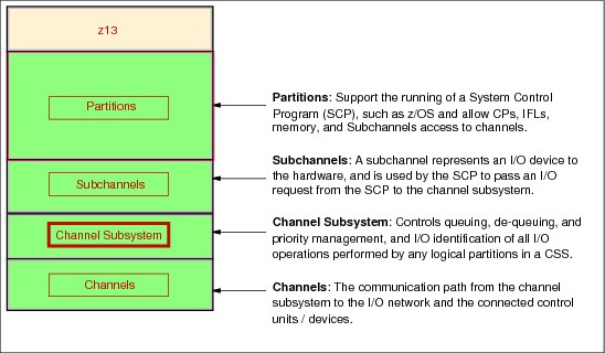
Figure 5-1 Channel subsystem overview
5.1.1 Multiple channel subsystems concept
The design of z Systems offers considerable processing power, memory size, and I/O connectivity. In support of the larger I/O capability, the CSS concept is scaled up correspondingly. The increased size provides relief for the number of supported logical partitions (LPARs), channels, and devices that are available to the system.
A single channel subsystem allows the definition of up to 256 channel paths. To overcome this limit, the multiple channel subsystems concept was introduced. The architecture provides for up to six channel subsystems. The structure of the multiple CSSs provides channel connectivity to the defined LPARs in a manner that is transparent to the subsystems and application programs. This configuration enables the definition of a balanced configuration for the processor and I/O capabilities.
The CSSs are numbered 0 - 5, which is referred to as the CSS image ID (CSSID 0, 1, 2, 3, 4, or 5). These CSSs are also referred to as logical channel subsystems (LCSSs). Each CSS can have 1 - 256 channels. CSSs 0 - 4 can be configured to 1 - 15 LPARs, CSS 5 can be configured to 1 - 10 LPARs. Therefore, the six CSSs support a maximum of 85 LPARs.
5.1.2 CSS elements
The CSS is composed of the following elements:
Subchannels
A subchannel provides the logical representation of a device to a program. It contains the information that is required for sustaining a single I/O operation. A subchannel is assigned for each device that is defined to the LPAR.
Multiple subchannel sets, which are described in 5.1.3, “Multiple subchannel sets” on page 186, are available to increase addressability. Four subchannel sets per CSS are supported on a z13. Subchannel set 0 can have up to 63.75 K subchannels, and subchannel sets 1, 2 and 3 can have up to 64 K minus one subchannel each.
Channel paths
Each CSS can have up to 256 channel paths. A channel path is a single interface between a server and one or more control units. Commands and data are sent across a channel path to run I/O requests.
Channel path identifier
Each channel path in the system is assigned a unique identifier value that is known as a channel-path identifier (CHPID). A total of 256 CHPIDs are supported by the CSS, and a maximum of 1536 are supported per system (CPC).
The channel subsystem communicates with I/O devices through channel paths between the channel subsystem and control units. On z Systems, a CHPID number is assigned to a physical location (slot/port) by the client by using the hardware configuration definition (HCD) tool or input/output configuration program (IOCP).
Control units
A control unit provides the logical capabilities that are necessary to operate and control an I/O device. It adapts the characteristics of each device so that it can respond to the standard form of control that is provided by the CSS. A control unit can be housed separately, or can be physically and logically integrated with the I/O device, the channel subsystem, or within the system itself.
I/O devices
An I/O device provides external storage, a means of communication between data-processing systems, or a means of communication between a system and its environment. In the simplest case, an I/O device is attached to one control unit and is accessible through one or more channel paths.
5.1.3 Multiple subchannel sets
Do not confuse the multiple subchannel sets (MSS) function with multiple channel subsystems. In most cases, a subchannel represents an addressable device. For example, a disk control unit with 30 drives uses 30 subchannels for base addresses. An addressable device is associated with a device number, which is commonly (but incorrectly) known as the device address.
Subchannel numbers
Subchannel numbers (including their implied path information to a device) are limited to four hexadecimal digits by the architecture (0x0000 - 0xFFFF). Four hexadecimal digits provide
64 K addresses, which are known as a set.
64 K addresses, which are known as a set.
IBM has reserved 256 subchannels, leaving over 63 K subchannels for general use.1 Again, addresses, device numbers, and subchannels are often used as synonyms, although this is not technically accurate. You might hear that there is a maximum of 63.75 K addresses or a maximum of 63.75 K device numbers.
The processor architecture allows for sets of subchannels (addresses), with a current implementation of four sets. Each set provides 64 K addresses. Subchannel set 0, the first set, reserves 256 subchannels for IBM use. Each of subchannel sets 1, 2, and 3 provides
64 K minus one subchannel. In principle, subchannels in either set can be used for any device-addressing purpose. These subchannels are referred to as special devices.
64 K minus one subchannel. In principle, subchannels in either set can be used for any device-addressing purpose. These subchannels are referred to as special devices.
Figure 5-2 summarizes the multiple channel subsystems and multiple subchannel sets.

Figure 5-2 Multiple channel subsystems and multiple subchannel sets
The additional subchannel sets, in effect, add an extra high-order digit (either 0, 1, 2, or 3) to existing device numbers. For example, you might think of an address as 08000 (subchannel set 0), 18000 (subchannel set 1), 28000 (subchannel set 2), or 38000 (subchannel set 3). Adding a digit is not done in system code or in messages because of the architectural requirement for four-digit addresses (device numbers or subchannels). However, certain messages contain the subchannel set number. You can mentally use that as a high-order digit for device numbers. Only a few requirements refer to the subchannel sets 1, 2, and 3 because they are used only for these special devices. JCL, messages, and programs rarely refer directly to these special devices.
Moving these special devices into an alternative subchannel set creates more space for device number growth. The appropriate subchannel set number must be included in the IOCP definitions or in the HCD definitions that produce the input/output configuration data set (IOCDS). The subchannel set number defaults to zero.
IPL from an alternative subchannel set
The z13 and the zEC12 support IPL from subchannel set 1 (SS1), subchannel set 2 (SS2), or subchannel set 3 (SS3) in addition to subchannel set 0. Devices that are used early during IPL processing now can be accessed by using subchannel set 1, subchannel set 2, or subchannel set 3. This configuration allows the users of Metro Mirror (formerly PPRC) secondary devices that are defined by using the same device number and a new device type in an alternative subchannel set to be used for IPL, an I/O definition file (IODF), and stand-alone memory dump volumes when needed.
IPL from an alternative subchannel set is supported by z/OS V1.13 or later, and Version 1.12 and Version 1.11 with program temporary fixes (PTFs). IPL applies to the Fibre Channel connection (FICON) and High Performance FICON for z Systems (zHPF) protocols.
The display ios,config command
The z/OS display ios,config(all) command that is shown in Figure 5-3 includes information about the MSSs.
|
D IOS,CONFIG(ALL)
IOS506I 11.32.19 I/O CONFIG DATA 340
ACTIVE IODF DATA SET = SYS6.IODF39
CONFIGURATION ID = L06RMVS1 EDT ID = 01
TOKEN: PROCESSOR DATE TIME DESCRIPTION
SOURCE: SCZP501 14-10-31 08:51:47 SYS6 IODF39
ACTIVE CSS: 0 SUBCHANNEL SETS CONFIGURED: 0, 1, 2, 3
CHANNEL MEASUREMENT BLOCK FACILITY IS ACTIVE
LOCAL SYSTEM NAME (LSYSTEM): SCZP501
HARDWARE SYSTEM AREA AVAILABLE FOR CONFIGURATION CHANGES
PHYSICAL CONTROL UNITS 8099
CSS 0 - LOGICAL CONTROL UNITS 3996
SS 0 SUBCHANNELS 54689
SS 1 SUBCHANNELS 58862
SS 2 SUBCHANNELS 65535
SS 3 SUBCHANNELS 65535
CSS 1 - LOGICAL CONTROL UNITS 4088
SS 0 SUBCHANNELS 65280
SS 1 SUBCHANNELS 65535
SS 2 SUBCHANNELS 65535
SS 3 SUBCHANNELS 65535
CSS 2 - LOGICAL CONTROL UNITS 4088
SS 0 SUBCHANNELS 65280
SS 1 SUBCHANNELS 65535
SS 2 SUBCHANNELS 65535
SS 3 SUBCHANNELS 65535
CSS 3 - LOGICAL CONTROL UNITS 4088
SS 0 SUBCHANNELS 65280
SS 1 SUBCHANNELS 65535
SS 2 SUBCHANNELS 65535
SS 3 SUBCHANNELS 65535
CSS 4 - LOGICAL CONTROL UNITS 4088
SS 0 SUBCHANNELS 65280
SS 1 SUBCHANNELS 65535
SS 2 SUBCHANNELS 65535
SS 3 SUBCHANNELS 65535
CSS 5 - LOGICAL CONTROL UNITS 4088
SS 0 SUBCHANNELS 65280
SS 1 SUBCHANNELS 65535
SS 2 SUBCHANNELS 65535
SS 3 SUBCHANNELS 65535
|
Figure 5-3 Output for display ios,config(all) command with MSS
5.1.4 Parallel access volumes and extended address volumes
Parallel access volume (PAV) support enables a single z Systems server to simultaneously process multiple I/O operations to the same logical volume. This feature can help significantly reduce device queue delays. Dynamic PAV allows the dynamic assignment of aliases to volumes to be under Workload Manager (WLM) control.
With the availability of HyperPAV, the requirement for PAV devices is reduced. HyperPAV allows an alias address to be used to access any base on the same control unit image per I/O base. It also allows different HyperPAV hosts to use one alias to access different bases, which reduces the number of alias addresses required. HyperPAV is designed to enable applications to achieve equal or better performance than the original PAV feature alone while also using the same or fewer z/OS resources. HyperPAV is an optional feature on the IBM DS8000® series.
To further reduce the complexity of managing large I/O configurations, z Systems introduced extended address volume (EAV). EAV is designed to build large disk volumes by using virtualization technology. By being able to extend the disk volume size, a client might potentially need fewer volumes to hold the data. This configuration makes systems management and data management less complex.
5.1.5 Logical partition name and identification
No LPARs can exist without at least one defined CSS. LPARs are defined to a CSS, not to a system. An LPAR is associated with one CSS only.
An LPAR is identified through its name, its identifier, and its multiple image facility (MIF) image ID (MIF ID). The LPAR name is defined through HCD or the IOCP, and is the partition name in the RESOURCE statement in the configuration definitions. Each name must be unique across the CPC.
The LPAR identifier is a number 00 - 5F. It is assigned by the user on the image profile through the Support Element (SE) or the Hardware Management Console (HMC). It is unique across the CPC, and also might be referred to as the user LPAR ID (UPID).
The MIF ID is a number that is defined through the HCD tool or directly through the IOCP. It is specified in the RESOURCE statement in the configuration definitions. It is in the range of 1 - F and is unique within a CSS. However, because of the multiple CSSs, the MIF ID is not unique within the CPC. Because the z13 CSS5 supports only 10 LPARs, the range for the MIF ID in this CSS is 1 - A.
The multiple image facility enables resource sharing across LPARs within a single CSS, or across the multiple CSSs. When a channel resource is shared across LPARs in multiple CSSs, the configuration is called spanning. Multiple CSSs can specify the same MIF image ID. However, the combination CSSID.MIFID is unique across the CPC.
Dynamic addition or deletion of a logical partition name
All undefined LPARs are reserved partitions. They are automatically predefined in the hardware system area (HSA) with a name placeholder and a MIF ID.
Summary of identifiers
It is a preferred practice to establish a naming convention for the LPAR identifiers. Figure 5-4 summarizes the identifiers and how they are defined. You can use the CSS number concatenated to the MIF ID, which means that LPAR ID 3A is in CSS 3 with MIF ID A. This fits within the allowed range of LPAR IDs, and conveys helpful information to the user.

Figure 5-4 CSS, LPAR, and identifier example
5.1.6 Physical channel ID (PCHID)
A PCHID reflects the physical identifier of a channel-type interface. A PCHID number is based on the PCIe drawer or I/O drawer location, the channel feature slot number, and the port number of the channel feature. A hardware channel is identified by a PCHID. The physical channel, which uniquely identifies a connector jack on a channel feature, is known by its PCHID number.
Do not confuse PCHIDs with CHPIDs. A CHPID does not directly correspond to a hardware channel port, and can be arbitrarily assigned. Within a single channel subsystem, 256 CHPIDs can be addressed. That gives a maximum of 1,536 CHPIDs when six CSSs are defined. Each CHPID number is associated with a single channel.
CHPIDs are not pre-assigned. Assign the CHPID numbers during installation by using the CHPID Mapping Tool (CMT) or HCD/IOCP. Assigning CHPIDs means that a CHPID number is associated with a physical channel/port location and a CSS. The CHPID number is still
00 - FF, and must be unique within a CSS. Any non-internal CHPID that is not defined with a PCHID can fail validation when you are attempting to build a production IODF or an IOCDS.
00 - FF, and must be unique within a CSS. Any non-internal CHPID that is not defined with a PCHID can fail validation when you are attempting to build a production IODF or an IOCDS.
5.1.7 Channel spanning
Channel spanning extends the MIF concept of sharing channels across LPARs to sharing physical channels across LPARs and channel subsystems.
Spanning is the ability for a physical channel (PCHID) to be mapped to CHPIDs that are defined in multiple channel subsystems. When so defined, channels can be transparently shared by any or all of the configured LPARs, regardless of the channel subsystem to which the LPAR is configured.
A channel is considered a spanned channel if the same CHPID number in different CSSs is assigned to the same PCHID in IOCP, or is defined as spanned in HCD.
For internal channels, such as Internal Coupling (IC) links and HiperSockets, the same situation applies, but with no PCHID association. They are defined with the same CHPID number in multiple CSSs.
In Figure 5-5, CHPID 04 is spanned to CSS0 and CSS1. Because it is an internal channel link, no PCHID is assigned. CHPID 06 is an external spanned channel and has a PCHID assigned.

Figure 5-5 zEC12 CSS - channel subsystems with channel spanning
CHPIDs that span CSSs reduce the total number of channels that are available. The total is reduced because no CSS can have more than 256 CHPIDs. For a z13 with two CSSs defined, a total of 512 CHPIDs is supported. If all CHPIDs are spanned across the two CSSs, only 256 channels are supported. For a z13 with six CSSs defined, a total of 1536 CHPIDs are supported. If all CHPIDs are spanned across the six CSSs, only 256 channels are supported.
Channel spanning is supported for internal links (HiperSockets and IC links) and for certain external links. External links that are supported include FICON Express16S, FICON Express8S, FICON Express8 channels, OSA-Express5S, OSA-Express4S, and Coupling Links.
5.1.8 Multiple CSSs construct
A z13 with multiple CSSs that are defined is shown in Figure 5-6. In this example, two channel subsystems are defined (CSS0 and CSS1). Each CSS has three LPARs with their associated MIF image identifiers.

Figure 5-6 z13 CSS connectivity
In each CSS, the CHPIDs are shared across all LPARs. The CHPIDs in each CSS can be mapped to their designated PCHIDs by using the CMT or manually by using the HCD or IOCP. The output of the CMT is used as input to HCD or the IOCP to establish the CHPID to PCHID assignments.
5.1.9 Adapter ID (AID)
When you use HCD or IOCP to assign a CHPID to a Parallel Sysplex over an InfiniBand (IFB) coupling link port, an Adapter ID (AID) number is required.
The AID is bound to the serial number of the fanout. If the fanout is moved, the AID moves with it. For more information, see “Adapter ID number assignment” on page 150.
5.1.10 Channel subsystem enhancement for I/O resilience
The z13 channel subsystem is enhanced to provide improved throughput and I/O service times when the following abnormal conditions occur:
•Multiple system workload spikes
•Multiple system resource contention in the storage area network (SAN) or at the control unit ports
•SAN congestion
•Improperly defined SAN configurations
•Dynamic changes in fabric routing
•Destination port congestion
This enhancement also might apply to Licensed Internal Code (LIC) failures in the SAN, channel extenders, Wavelength Division Multiplexers, and control units. When abnormal conditions occur that can cause an imbalance in I/O performance characteristics across a set of channel paths to the control unit, the channel subsystem intelligently uses the channels that provide optimal performance. This enhancement is accomplished by using the in-band I/O instrumentation and metrics of the z Systems FICON and zHPF protocols.
This channel subsystem enhancement is exclusive to z13 and zEC12, and is supported on all FICON channels when configured as CHPID type FC. This enhancement is transparent to operating systems.
5.2 I/O configuration management
For ease of management, use HCD to build and control the I/O configuration definitions. HCD support for multiple channel subsystems is available with z/VM and z/OS. HCD provides the capability to make both dynamic hardware and software I/O configuration changes.
The following tools are provided to help maintain and optimize the I/O configuration:
•IBM Configurator for e-business (eConfig): The eConfig tool is available from your IBM representative. It is used to create configurations or upgrades of an existing configuration, and it maintains the installed features of those configurations. Reports that are produced by eConfig are helpful in understanding the changes that are being made for a system upgrade, and what the final configuration will look like.
•Hardware configuration definition (HCD): HCD supplies an interactive dialog to generate the IODF, and later the IOCDS. Generally, use HCD or HCM to generate the I/O configuration rather than writing IOCP statements. The validation checking that HCD runs as data is entered helps minimize the risk of errors before the I/O configuration is implemented.
•Hardware Configuration Manager (HCM): HCM is a priced optional feature that supplies a graphical interface to HCD. It is installed on a PC and allows you to manage both the physical and the logical aspects of a mainframe hardware configuration.
•CHPID mapping tool (CMT): The CMT provides a mechanism to map CHPIDs onto PCHIDs as required. Additional enhancements are built into the CMT to meet the requirements of the z13. It provides the best availability choices for the installed features and defined configuration. The CMT is available for download from the IBM Resource Link website:
The health checker function in z/OS V1.10 introduces a health check in the I/O Supervisor. This application can help system administrators identify single points of failure in the I/O configuration.
5.3 Channel subsystem summary
The z13 supports the full architecture. Table 5-1 shows CSS-related information in terms of maximum values for devices, subchannels, LPARs, and CHPIDs.
Table 5-1 z13 CSS overview
|
Setting
|
z13
|
|
Maximum number of CSSs
|
6
|
|
Maximum number of CHPIDs
|
1536
|
|
Maximum number of LPARs supported per CSS
|
15 (CSS0 - CSS4), 10 (CSS5)
|
|
Maximum number of LPARs supported per system
|
85
|
|
Maximum number of HSA subchannels
|
16298 K (191.75 K per partition x 85 partitions)
|
|
Maximum number of devices
|
382.5 K (6 CSSs x 63.75 K devices)
|
|
Maximum number of CHPIDs per CSS
|
256
|
|
Maximum number of CHPIDs per LPAR
|
256
|
|
Maximum number of subchannels per LPAR
|
255.74 K (63.75 K + 3 x(64 K - 1))
|
All channel subsystem images (CSS images) are defined within a single IOCDS. The IOCDS is loaded and initialized into the hardware system area (HSA) during system power-on reset (POR). The HSA is pre-allocated in memory with a fixed size of 96 GB. This configuration eliminates planning for HSA and pre-planning for HSA expansion because HCD/IOCP always reserves the following items during the IOCDS process:
•Six CSSs
•Fifteen LPARs in each CSS0 to CSS4
•Ten LPARs in CSS5
•Subchannel set 0 with 63.75 K devices in each CSS
•Subchannel set 1 with 64 K minus one device in each CSS
•Subchannel set 2 with 64 K minus one device in each CSS
•Subchannel set 3 with 64 K minus one device in each CSS
All these items are activated and used with dynamic I/O changes.
Figure 5-7 shows a logical view of the relationships. CSS 0 - CSS 4 support up to 15 LPARs, and CSS 5 supports 10 LPARs. System-wide, a total of up to 85 LPARs are supported.

Figure 5-7 Logical view of z13 models, CSSs, IOCDS, and HSA
|
CPC drawer repair: The HSA can be moved from one CPC drawer to a different one in an enhanced availability configuration as part of a concurrent CPC drawer repair action.
|
The channel definitions of a CSS are not bound to a single CPC drawer. A CSS can define resources that are physically connected to any PCIe or InfiniBand cable of any CPC drawer in a multidrawer CPC.
5.4 System-initiated CHPID reconfiguration
The system-initiated CHPID reconfiguration function is designed to reduce the duration of a repair action and minimize operator interaction. It is used when a FICON channel or an Open Systems Adapter (OSA) port is shared across LPARs on a z13 server. When an I/O card is replaced (for a repair), it usually has a few failed channels and others that are still functioning.
To remove the card, all channels must be configured offline from all LPARs that share those channels. Without system-initiated CHPID reconfiguration, the IBM service support representative (IBM SSR) must contact the operators of each affected LPAR and have them set the channels offline. After the repair, the IBM SSR must contact them again to configure the channels back online.
With system-initiated CHPID reconfiguration support, the SE sends a signal to the channel subsystem that a channel must be configured offline. The channel subsystem determines all the LPARs that share that channel and sends an alert to the operating systems in those LPARs. The operating system then configures the channel offline without any operator intervention. This cycle is repeated for each channel on the card.
When the card is replaced, the SE sends another signal to the channel subsystem for each channel. This time, the channel subsystem alerts the operating system that the channel must be configured back online. This process minimizes operator interaction when you are configuring channels offline and online.
System-initiated CHPID reconfiguration is supported by z/OS.
5.5 Multipath initial program load
Multipath initial program load (IPL) helps increase availability and eliminates manual problem determination during IPL execution. This support allows IPL to complete, if possible, by using alternative paths when you are running an IPL from a device that is connected through FICON channels. If an error occurs, an alternative path is selected.
Multipath IPL is applicable to FICON channels (CHPID type FC). z/OS supports multipath IPL.
1 The number of reserved subchannels is 256. This is abbreviated to 63.75 K in this description to easily differentiate it from the 64 K minus one subchannel that are available in subchannel sets 1, 2, and 3. The informal name, 63.75 K subchannel, represents the following equation: (63 x 1024) + (0.75 x 1024) = 65280.
..................Content has been hidden....................
You can't read the all page of ebook, please click here login for view all page.