


Flash Express
This appendix covers the IBM Flash Express feature introduced on the zEC12 server.
Flash memory is a non-volatile computer storage technology. It was introduced on the market decades ago. Flash memory is commonly used today in memory cards, USB flash drives, solid-state drives (SSDs), and similar products for general storage and data transfer. Until recently, the high cost per gigabyte and limited capacity of SSDs restricted deployment of these drives to specific applications. Recent advances in SSD technology and economies of scale have driven down the cost of SSDs, making them a viable storage option for I/O-intensive enterprise applications.
An SSD, sometimes called a solid-state disk or electronic disk, is a data storage device that uses integrated circuit assemblies as memory to store data persistently. SSD technology uses electronic interfaces compatible with traditional block I/O hard disk drives. SSDs do not employ any moving mechanical components. This characteristic distinguishes them from traditional magnetic disks, such as hard disk drives (HDDs), which are electromechanical devices that contain spinning disks and movable read/write heads. With no seek time or rotational delays, SSDs can deliver substantially better I/O performance than HDDs. Flash SSDs demonstrate latencies that are 10 - 50 times lower than the fastest HDDs, often enabling dramatically improved I/O response times.
This appendix includes these sections:
C.1 Flash Express overview
Flash Express, which is implemented by using Flash SSDs mounted in Peripheral Component Interconnect Express (PCIe) Flash Express feature cards, is available as carry forward or as a new order for the z13.
Flash Express is an innovative solution that is designed to help improve availability and performance to provide a higher level of quality of service. It is designed to automatically improve availability for key workloads at critical processing times and to improve access time for critical business z/OS workloads. It can also reduce latency time during diagnostic collection (memory dump operations). In addition, CFCC Level 20 can take advantage of Flash Express as an overflow device for shared queue data in clustered WebSphere MQ deployments.
Figure C-1 illustrates how Flash Express introduces a new level in the z Systems storage hierarchy.
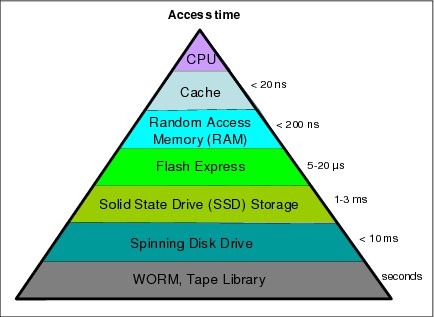
Figure C-1 zEC12 storage hierarchy
Flash Express is an optional PCIe card feature that is available on zEC12, zBC12, and z13 servers. Flash Express cards are supported in PCIe I/O drawers, and can be mixed with other PCIe I/O cards, such as Fibre Channel connection (FICON) Express16S, Crypto Express5S, and Open Systems Adapter (OSA) Express5S cards. You can order a minimum of two features (FC 0403) and a maximum of eight features.1 The cards are ordered in increments of two.
Flash Express cards are assigned one physical channel ID (PCHID) although they have no ports. No hardware configuration definition (HCD) or input/output configuration program (IOCP) definition is required for Flash Express installation. Flash Expressuses subchannels that are allocated from the .25K that is reserved in subchannel set 0. Similar to other PCIe I/O cards, redundant PCIe paths to Flash Express cards are provided by redundant I/O interconnect. Unlike other PCIe I/O cards, they can be accessed from the host only by a unique protocol.
A Flash Express PCIe adapter integrates four SSD cards of 400 GB each for a total of 1.4 TB of usable data per card, as shown in Figure C-2.

Figure C-2 Flash Express PCIe adapter
Each card (of a pair of cards) is installed in a PCIe I/O drawer in two different I/O domains. A maximum of two pairs are installed in a drawer with only one flash card per domain. Installing more than two pairs requires a second PCIe I/O drawer. Install the cards in the front of the installed drawers (slots 1 and 14) before you use the rear slots (25 and 33). Format each pair of cards before you use them.
Figure C-3 shows a PCIe I/O drawer that is fully populated with Flash Express cards.
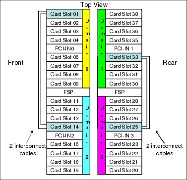
Figure C-3 PCIe I/O drawer that is fully populated with Flash Express cards
For higher resiliency and high availability, Flash Express cards are always installed in pairs. A maximum of four pairs are supported in a z13 system, providing a maximum of 5.6 TB of storage. In each Flash Express card, data is stored in a RAID configuration. If an SSD fails, data is reconstructed dynamically. The cards mirror each other over a pair of cables in a
RAID 10 configuration that combines mirroring and striping RAID capabilities. If either card fails, the data is available on the other card. Card replacement is concurrent with the client’s operations. In addition, Flash Express supports concurrent firmware upgrades.
RAID 10 configuration that combines mirroring and striping RAID capabilities. If either card fails, the data is available on the other card. Card replacement is concurrent with the client’s operations. In addition, Flash Express supports concurrent firmware upgrades.
The data that is written on the Flash Express cards is always stored encrypted with a volatile key. The card is only usable on the system with the key that encrypted it. For key management, both the primary and alternate Support Elements (SEs) have USB smart cards installed. The smart card contains both a unique key that is personalized for each system and a small Crypto engine that can run a set of security functions within the card.
C.2 Using Flash Express
Flash Express is designed to improve availability and latency from batch to interactive processing in z/OS environments, such as start of day. It helps accelerate start of day processing when there is heavy application activity. Flash Express also helps improve diagnostic procedures, such as supervisor call (SVC) memory dumps, and stand-alone memory dumps.
In z/OS, Flash Express memory is accessed by using the new z Systems Extended Asynchronous Data Mover (EADM) architecture. It is started with a Start subchannel instruction.
The Flash Express PCIe cards are shareable across logical partitions (LPARs). Flash Express memory can be assigned to z/OS LPARs, such as the main storage. It is dedicated to each LPAR. You can dynamically increase the amount of Flash Express memory that is allocated to an LPAR.
Flash Express is supported by z/OS 1.13 plus PTFs, and z/OS 2.1 for the z/OS paging activity and SVC memory dumps. Using Flash Express memory, 1 MB large pages become pageable. It is expected to provide applications with substantial improvement in SVC memory dump data capture time. Flash Express is expected to provide the applications with improved resiliency and speed, and make large pages pageable.
Flash Express memory in the CPC is assigned to a coupling facility (CF) partition by using hardware definition windows the same way that it is assigned to the z/OS partitions.
Flash Express use by the CF provides emergency capacity to handle WebSphere MQ shared queue buildups during abnormal situations, such as where “putters” are putting to the shared queue, but “getters” are transiently not getting from the shared queue, or other such transient producer or consumer mismatches on the queue. No new level of WebSphere MQ is required for this support.
Linux for z Systems (Red Hat Enterprise Linux and SUSE Linux enterprise) can use Flash Express as temporary storage. Other software subsystems might take advantage of Flash Express in the future.
Table C-1 gives the minimum support requirements for Flash Express.
Table C-1 Minimum support requirements for Flash Express
|
Operating system
|
Support requirements
|
|
z/OS
|
z/OS V1R131 and V2R1
|
|
CFCC
|
CF Level 20
|
1 Web delivery and program temporary fixes (PTFs) are required.
You can use the Flash Express allocation windows on the SE or Hardware Management Console (HMC) to define the initial and maximum amount of Flash Express available to an LPAR. The maximum memory that is allocated to an LPAR can be dynamically changed. On z/OS, this process can also be done by using an operator command. Flash memory can also be configured offline to an LPAR.
Figure C-4 gives a sample SE/HMC interface that is used for Flash Express allocation.

Figure C-4 Sample SE/HMC window for Flash Express allocation to LPAR
The SE user interface for Flash Express provides the following types of actions:
•Flash status and control: Displays the list of adapters that are installed in the system and their state
•Manage Flash allocation: Displays the amount of flash memory on the system
•View Flash allocations: Displays a table of flash information for one partition
•View Flash: Displays information for one pair of flash adapters
Physical Flash Express PCIe cards are fully virtualized across LPARs. Each LPAR can be configured with its own storage-class memory (SCM) address space. The size of Flash Express memory that is allocated to a partition is done by amount, not by card size. The hardware supports error isolation, transparent mirroring, centralized diagnostic procedures, hardware logging, and recovery, independently from the software.
At IPL, z/OS detects whether flash is assigned to the partition. z/OS automatically uses Flash Express for paging unless otherwise specified by using the new z/OS PAGESCM=NONE parameter. All paging data can be on Flash Express memory. The function is easy to use, and there is no need for capacity planning or placement of data on Flash Express cards.
Figure C-5 gives an example of Flash Express allocation between two z/OS LPARs.

Figure C-5 Flash Express allocation in z/OS LPARs
Flash Express memory is a faster paging device than HDD. It replaces disks, not memory. It is suitable for workloads that can tolerate paging. It does not benefit workloads that cannot afford to page. The z/OS design for Flash Express memory does not completely remove the virtual constraints that are created by a paging spike in the system. The z/OS paging subsystem works with a mix of internal Flash Express and external disks. Flash Express improves paging performance.
Currently, 1 MB large pages are not pageable. With the introduction of Flash Express, 1 MB large pages can be on Flash Express and pageable.
Table C-2 introduces, for a few z/OS data types that are supported by Flash Express, the choice criteria for data placement on Flash Express or on disk.
Table C-2 Flash Express z/OS supported data types
|
Data type
|
Data page placement
|
|
Pageable link pack area (PLPA)
|
At IPL/NIP time, PLPA pages are placed both on flash and disk.
|
|
Virtual input/output (VIO)
|
VIO data is always placed on disk (first to VIO accepting data sets, with any spillover flowing to non-VIO data sets).
|
|
IBM HyperSwap Critical Address Space data
|
If flash space is available, all virtual pages that belong to a HyperSwap Critical Address Space are placed in flash memory.
If flash space is not available, these pages are kept in memory and only paged to disk when the system is real storage constrained, and no other alternatives exist.
|
|
Pageable large pages
|
If contiguous flash space is available, pageable large pages are written to flash.
|
|
All other data
|
If space is available on both flash and disk, the system makes a selection that is based on response time.
|
Flash Express is used by the Auxiliary Storage Manager (ASM) with paging data sets to satisfy page-out and page-in requests received from the Real Storage Manager (RSM). It supports 4 KB and 1 MB page sizes. ASM determines where to write a page based on space availability, data characteristics, and performance metrics. ASM still requires definition of a PLPA, Common, and at least one local paging data set. VIO pages are only written to DASD because persistence is needed for warm starts.
A new PAGESCM keyword in the IEASYSxx member defines the minimum amount of flash to be reserved for paging. The value can be specified in units of MB, GB, or TB. NONE indicates that the system does not use flash for paging. ALL (the default) indicates that all flash that is defined to the partition is available for paging.
The following new messages are issued during z/OS IPL and indicate the status of SCM:
IAR031I USE OF STORAGE-CLASS MEMORY FOR PAGING IS ENABLED - PAGESCM=ALL, ONLINE=00001536M
IAR032I USE OF STORAGE-CLASS MEMORY FOR PAGING IS NOT ENABLED - PAGESCM=NONE
The D ASM and D M commands are enhanced to display flash-related information/status:
•D ASM lists the SCM status along with paging data set status.
•D ASM,SCM displays a summary of SCM usage.
•D M=SCM displays the SCM online/offline and increment information.
•D M=SCM(DETAIL) displays detailed increment-level information.
The CONFIG ONLINE command is enhanced to allow bringing more SCMs online:
CF SCM (amount), ONLINE
C.3 Security on Flash Express
Data that is stored on Flash Express is encrypted by a strong encryption symmetric key that is in a file on the SE hard disk. This key is also known as the Flash encryption key/authentication key. The firmware management of the Flash Express adapter can generate an asymmetric transport key in which the flash encryption key/authentication key is wrapped. This transport key is used while in transit from the SE to the firmware management of the Flash Express adapter.
The SE has an integrated card reader into which one smart card at a time can be inserted. When an SE is “locked down,” removing the smart card is not an option unless you have the physical key to the physical lock.
C.3.1 Integrated Key Controller
The SE initializes the environment by starting APIs within the Integrated Key Controller (IKC). The IKC loads an applet to a smart card inserted in the integrated card reader. The smart card applet, as part of its installation, creates a Rivest-Shamir-Adleman algorithm (RSA) key pair, the private component of which never leaves the smart card. However, the public key is exportable. The applet also creates two Advanced Encryption Standard (AES) symmetric keys. One of these AES keys is known as the key-encrypting key (KEK), which is retained on the smart card. The KEK can also be exported. The other AES key becomes the Flash encryption key/authentication key and is encrypted by the KEK.
A buffer is allocated containing the KEK-encrypted flash encryption key/authentication key and the unique serial number of the SE. The buffer is padded per Public-Key Cryptography Standards #1 (PKCS #1) and then encrypted by the smart card RSA public key. The encrypted content is then written to a file on the SE hard disk.
This design defines a tight coupling of the file on the SE to the smart card. The coupling ensures that any other SE is not able to share the file or the smart card that is associated with an SE. It ensures that the encrypted files are unique and all such smart cards are uniquely tied to their SEs.
All key generation, encryption, and decryption occur on the smart card. Keys are never in the clear. The truly sensitive key, the flash encryption key/authentication key, is only in the file on the SE until it is served to the firmware management of the Flash Express adapter.
Figure C-6 shows the cryptographic keys that are involved in creating this tight-coupling design.

Figure C-6 Integrated Key Controller
The flash encryption key/authentication key can be served to the firmware management of the Flash Express adapter. This process can be either upon request from the firmware at initial microcode load (IML) time or from the SE as the result of a request to “change” or “roll” the key.
During the alternate SE initialization, APIs are called to initialize the alternate smart card in it with the applet code and create the RSA public/private key pair. The API returns the public key of the smart card that is associated with the alternate SE. This public key is used to encrypt the KEK and the Flash encryption key/authentication key from the primary SE. The resulting encrypted file is sent to the alternate SE for redundancy.
C.3.2 Key serving topology
In a key serving topology, the SE is the key server and the IKC is the key manager. The SE is connected to the firmware management of the Flash Express adapter through a secure communications line. The firmware manages the transportation of the Flash encryption key/authentication key through internal system paths. Data in the adapter cache memory is backed up by a flash-backed DRAM module. This module can encrypt the data with the Flash encryption key/authentication key.
The firmware management of the Flash Express adapter generates its own transport RSA asymmetric key pair. This pair is used to wrap the Flash encryption key/authentication key while in transit between the SE and the firmware code.
Figure C-7 on page 498 shows the following key serving topology:
1. The firmware management of the Flash Express adapter requests the Flash encryption key/authentication key from the SE at IML time. When this request arrives, the firmware public key is passed to the SE to be used as the transport key.
2. The file that contains the KEK-encrypted Flash encryption key/authentication key and the firmware public key is passed to the IKC. The IKC sends the file contents and the public key to the smart card.
3. The applet on the smart card decrypts the file contents and the Flash encryption key/authentication key. It then re-encrypts the Flash encryption key/authentication key with the firmware public key.
4. This encrypted key is then passed back to the SE, which forwards it on to the firmware management of the Flash Express adapter code.
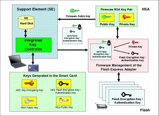
Figure C-7 Key serving topology
C.3.3 Error recovery scenarios
Possible error scenarios are described in this section.
Primary Support Element failure
When the primary SE fails, a switch is made to the alternate SE, which then becomes the new primary. When the former primary is brought back up, it becomes the alternate SE. The KEK and the Flash encryption key/authentication key from the primary SE were already sent to the alternate SE for redundancy at initialization time.
Removal of a smart card
If a smart card is removed from the card reader, the card reader signals the event to the IKC listening code. The IKC listener then calls the SE to take the appropriate action. The appropriate action can involve deleting the flash encryption key or authentication key file.
If the smart card is removed while the SE is powered off, there is no knowledge of the event. However, when the SE is powered on, notification is sent to the system administrator.
Primary Support Element failure during IML serving of the flash key
If the primary SE fails during the serving of the key, the alternate SE takes over as the primary and restarts the key serving operation.
Alternate Support Element failure during switchover from the primary
If the alternate SE during the switchover when the primary SE fails, the key serving state is lost. When the primary comes back up, the key serving operation can be restarted.
Primary and alternate Support Elements fail
If the primary and the alternate Support Elements both fail, the key cannot be served. If the devices are still up, the key is still valid. If either or both Support Elements are recovered, the files holding the Flash encryption key/authentication key can still be valid. This is true even in a key roll case. Both new and current (old) keys need to be available until the key serving operation is complete.
If both SEs are down, and the Flash Express goes down and comes back online before the SEs become available, all data on the Flash Express is lost. Reformatting is then necessary when the device is started.
If both Flash Express devices are still started, get the primary SE back online as fast as possible with the Flash encryption key/authentication key file and associated smart card still intact. After that happens, the alternate SE can be brought online with a new smart card and taken through the initialization procedure.
1 FC 0402 can also be carried forward. The total number of Flash Express features (carry forward + new order) cannot exceed eight per z Systems server.
..................Content has been hidden....................
You can't read the all page of ebook, please click here login for view all page.