


Reliability, availability, and serviceability
This chapter describes the reliability, availability, and serviceability (RAS) features of the IBM z13.
The z13 design is focused on providing higher availability by reducing planned and unplanned outages. RAS can be accomplished with improved concurrent replace, repair, and upgrade functions for processors, memory, drawers, and I/O. RAS also extends to the nondisruptive capability for installing Licensed Internal Code (LIC) updates. In most cases, a capacity upgrade can be concurrent without a system outage. As an extension to the RAS capabilities, environmental controls are implemented in the system to help reduce power consumption and meet cooling requirements.
The design of the memory on the z13 is based on the fully redundant memory infrastructure, Redundant Array of Independent Memory (RAIM). RAIM was first introduced with the z196. The z Systems servers are the only systems in the industry that offer this level of memory design.
RAS also provides digitally signed delivery and transmission of microcode (LIC), fixes, and restoration/backup files. Any data that is transmitted to IBM Support is encrypted.
The design goal for the z13 is to remove all sources of planned outages.
This chapter includes the following sections:
9.1 The RAS strategy
The RAS strategy is to manage change by learning from previous generations and investing in new RAS function to eliminate or minimize all sources of outages. Enhancements to z Systems RAS designs are implemented on the z13 system through the introduction of new technology, structure, and requirements. Continuous improvements in RAS are associated with new features and functions to ensure z Systems deliver exceptional value to clients.
As described throughout this book, the z13 server introduced several changes from prior z Systems generations. Although the RAS design objective has not changed, many new RAS functions were introduced to mitigate changes in the server design. The RAS design on z13 is based on continuous improvements to address changes in technology, structure, complexity, and touches.
9.2 Technology change
A technology change in z13 is that the central processor (CP) and system cache (SC) chips are designed as single chip modules (SCMs). Further improvements to address soft errors include bus interleaving, and smaller structures and register arrays. Cache sizes and densities were increased in z13. In the cache structure, the L3 wordline structure was changed, subarray masking was introduced, and the hardware system area (HSA) was changed to detect and demote uncorrectable errors. A new L4 cache design contains improved symbol error correction code (ECC) to handle correctable errors more effectively. A list of technology changes is shown in Table 9-1.
Table 9-1 Technology changes
|
All models use SCMs as opposed to multiple chip modules (MCMs) in previous generations.
|
|
Increased interleaving on buses and register files to mitigate soft errors.
|
|
Increased cache sizes and densities.
|
|
Improved address checking for array and register files to better protect against soft error disturbances in the processors.
|
|
Improved L3 cache macro structure such that wordline failures do not affect all compartments.
|
|
Dynamic L3 cache monitor (“stepper”) to find and demote HSA lines in the cache.
|
|
Symbol ECC on L3 cache configuration array.
|
|
Symbol ECC on the L4 cache data.
|
|
Symbol ECC on the L4 cache directory data.
|
|
Symbol ECC on L4 cache configuration array.
|
|
Dynamic L4 cache subarray masking: Active monitoring of a masked subarray.
|
|
Symbol ECC on the store protects key cache data.
|
9.3 Structure change
A structure change in z13 is that the processing infrastructure within the CPC was designed using drawer technology. Cables are keyed to ensure that correct lengths are plugged, plug detection ensures correct location, and custom latches ensure retention. Further improvements to the fabric bus include the introduction of symmetric multiprocessing (SMP) cables that connect the drawers together. To improve FRU isolation, time domain reflectometry (TDR) techniques are applied to the SMP cables, between chips (CP-CP, CP-SC, and SC-SC), and between the CP chips and dual inline memory modules (DIMMs).
With a two-node CPC drawer structure, the z13 design protects system resources and allows activation with half-drawer resources in degraded mode, if necessary. Enhancements to thermal RAS were introduced as well, such as a field-replaceable water manifold for CP cooling. Two redundant oscillator cards are attached to the CPC drawers through a rigid backplane. A list of structure changes is shown in Table 9-2.
Table 9-2 Structure changes
|
Processing infrastructure that is designed by using drawer technology (zEC12 used book technology).
|
|
Keyed cables and plugging detection.
|
|
SMP cables that are used for fabric bus connections.
|
|
Node level degrade on single drawer configuration.
|
|
Water manifold is an FRU.
|
|
Master-master redundant oscillator design in the main memory.
|
|
Processor and nest chips are separate FRUs (like BC servers).
|
|
Point of load cards are separate FRUs (replaces the VTM function in book).
|
|
Oscillator cards plug straight in (no blind mating of connector)
|
|
Built in time domain reflectometer for FRU isolation in interface errors
|
9.4 Reducing complexity
The z13 also introduced a number of enhancements that reduced system RAS complexity. Specifically, in the memory subsystem design, simplifications were made in RAIM recovery. Memory DIMMs are no longer cascaded, which eliminates the double FRU call for DIMM errors. Independent channel recovery with replay buffers on all interfaces allows recovery of a single DIMM channel, while other channels remain active. Further redundancies are incorporated in I/O pins for clock lines to main memory, which eliminates the loss of memory clocks because of connector (pin) failure. A list of RAS enhancements that reduce service complexity is shown in Table 9-3.
Table 9-3 Reducing service complexity
|
Continued use of RAIM ECC.
|
|
No cascading of memory DIMM simplified the recovery design.
|
|
Replay buffer for hardware retry on soft errors on the main memory interface.
|
|
Redundant I/O pins for clock lines to main memory.
|
9.5 Reducing touches
z Systems RAS efforts focus on the reduction of unscheduled, scheduled, planned, and unplanned outages. z Systems has a long history of demonstrated RAS improvements, and this effort continues with changes that reduce service touches on the system. Firmware has been updated to improve filtering and resolution of errors that do not require action. Enhanced integrated sparing in processor cores, cache relocates, N+1 SEEPROM and POL N+2 redundancies, and DRAM marking also are incorporated to reduce touches. A list of RAS enhancements to reduce service touches is shown in Table 9-4.
Table 9-4 Reducing service touches
|
Improved error resolution to enable filtering
|
|
Enhanced integrated sparing in processor cores
|
|
Cache relocates
|
|
N+1 SEEPROM
|
|
N+2 POL
|
|
DRAM marking
|
|
(Dynamic) Spare lanes for SC-SC, CP-SC, CP-CP, CP-mem, and SC-SMP fabric
|
|
N+2 radiator pumps, controllers, blowers, and sensors
|
|
SCH N+1 (with N+1 SCH power supplies)
|
|
N+1 SE (with N+1 SE power supplies)
|
|
Redundant SEEPROM on memory DIMM
|
|
Redundant temperature sensor (one SEEPROM and ONE temperature sensor per I2C bus)
|
|
FICON forward error correction
|
9.6 z13 availability characteristics
The following functions include availability characteristics on the z13:
•Enhanced drawer availability (EDA)
EDA is a procedure under which a CPC drawer in a multidrawer system can be removed and reinstalled during an upgrade or repair action with no impact on the workload.
•Concurrent memory upgrade or replacement
Memory can be upgraded concurrently by using Licensed Internal Code Configuration Control (LICCC) if physical memory is available on the drawers. If the physical memory cards must be changed in a multidrawer configuration, requiring the drawer to be removed, the EDA function can be useful. It requires the availability of more resources on other drawers or reducing the need for resources during this action. To help ensure that the appropriate level of memory is available in a multiple-drawer configuration, select the flexible memory option. This option provides more resources to use EDA when repairing a drawer or memory on a drawer. They also are available when upgrading memory where larger memory cards might be required.
Memory can be upgraded concurrently by using LICCC if physical memory is available. The plan-ahead memory function that is available with the z13 allows you to plan for nondisruptive memory upgrades by having the system pre-plugged based on a target configuration. You can enable the pre-plugged memory by placing an order through LICCC.
•Enhanced driver maintenance (EDM)
One of the greatest contributors to downtime during planned outages is LIC driver updates that are performed in support of new features and functions. The z13 is designed to support the concurrent activation of a selected new driver level.
•IBM zAware
IBM z Advanced Workload Analysis Reporter (IBM zAware) is an availability feature that uses near real-time continuous learning algorithms, which provide a diagnostic capability that is intended to help you quickly pinpoint problems, which in turn can help you to address rapidly service disruptions. IBM zAware uses analytics to examine z/OS messages and Linux on z Systems logs (syslogd) to find unusual patterns, inconsistencies, and variations. For more information about IBM zAware, see 9.13, “IBM z Advanced Workload Analysis Reporter” on page 379.
•Flash Express
The Flash Express feature allows customers to recover from application failures more quickly by speeding up the memory dump process. The internal flash storage solution is protected by two Peripheral Component Interconnect Express (PCIe) adapters that mirror to each other. If either card fails, the data is available on the other card. Data is stored over multiple flash devices in pairs, in a RAID configuration. If the flash device fails, the data is reconstructed dynamically. For more information about Flash Express, see 9.14, “RAS capability for Flash Express” on page 380.
•Redundant IBM z BladeCenter Extension (zBX) Model 004 configurations
Redundant hardware configurations within the zBX provide the capacity to repair concurrently the BladeCenter components. Top of Rack (ToR) switches, present on the first zBX rack (frame B), are redundant. This redundancy allows firmware application and repair actions to be fully concurrent. Power Distribution Units (PDUs) provide redundant (N+1) connections to the main power source, improving zBX availability. The internal and external network connections are redundant throughout all the zBX racks, ToRs, and BladeCenters.
•Plan Ahead for Balanced Power (FC 3003)
The Plan Ahead for Balanced Power feature allows you to order the maximum number of bulk power regulators (BPRs) on any server configuration. This feature helps to ensure that your configuration is in a balanced power environment if you intend to add CPC drawers and I/O drawers to your server in the future. Regardless of your configuration, all six BPR pairs will be shipped, installed, and activated.
|
Note: When this feature is ordered, a corequisite feature, the Plan Ahead for Line Cords feature (FC 2000), is automatically selected.
|
•Concurrent fanout addition or replacement
A PCIe or InfiniBand (IFB) fanout card provides the path for data between memory and I/O through PCIe or IFB cables. With the z13, a hot-pluggable and concurrently upgradeable fanout card is available. Up to 10 PCIe and up to four IFB fanout cards per CPC drawer are available for the z13. A z13 Model NC9 (or NE1) holds four CPC drawers and can have 40 PCIe fanout slots and 16 IFB fanout slots. Internal I/O paths from the CPC drawer fanout ports to either a PCIe drawer or an I/O drawer are spread across multiple CPC drawers (for models N63, N96, NC9, and NE1) and across different nodes within a single CPC drawer model N30. During an outage, a fanout card that is used for I/O can be repaired concurrently while redundant I/O interconnect ensures that no I/O connectivity is lost.
•Redundant I/O interconnect
Redundant I/O interconnect helps maintain critical connections to devices. The z13 allows a single drawer, in a multidrawer system, to be removed and reinstalled concurrently during an upgrade or repair. Connectivity to the system I/O resources is maintained through a second path from a different drawer.
•Dynamic oscillator switch-over
The z13 has two oscillator cards, a primary and a backup. During a primary card failure, the backup card is designed to detect transparently the failure, switch over, and provide the clock signal to the system.
•Processor unit (PU) sparing
The z13 has two spare PUs to maintain performance levels if an active CP, Internal Coupling Facility (ICF), Integrated Facility for Linux (IFL), IBM z Integrated Information Processor (zIIP), integrated firmware processor (IFP), or System Assist Processor (SAP) fails. Transparent sparing for failed processors is supported. There are two spare PUs per system and sparing is supported across the drawers in the unlikely event that the drawer with the failure does not have spares available.
•Application preservation
Application preservation is used where a CP fails and there are no spares left. The state of the failing CP is passed to another active CP, where the operating system uses it to successfully resume the task, in most cases without client intervention.
•Cooling improvements
The z13 air-cooled configuration comes with a newly designed radiator cooling system. The radiator pumps, blowers, controls, and sensors are N+2 redundant. In normal operation, one active pump supports the system. A second pump is turned on and the original pump is turned off periodically, which improves reliability of the pumps. The replacement of pumps or blowers is concurrent with no performance impact.
A water-cooling system also is an option in z13, with water-cooling unit (WCU) technology. Two redundant WCUs run with two independent chilled water feeds. One WCU and one water feed can support the entire system load. The water-cooled configuration is backed up by the rear door heat exchangers in the rare event of a problem with the chilled water facilities of the customer.
A new design of the rear door covers addresses past data center issues regarding airflow challenges. The covers can be installed for a vectored down or up orientation, fulfilling the requirements of the modern data center.
•FICON Express16S with Forward Error Correction (FEC)
FICON Express16S features provide a new standard for transmission of data over
16 Gbps links by using 64b/66b encoding. The new standard that is defined by T11.org FC-FS-3 is more efficient than the current 8b/10b encoding.
16 Gbps links by using 64b/66b encoding. The new standard that is defined by T11.org FC-FS-3 is more efficient than the current 8b/10b encoding.
FICON Express16S channels running at 16 Gbps can take advantage of FEC capabilities when connected to devices that support FEC.
FEC allows FICON Express16S channels to operate at higher speeds, over longer distances, with reduced power and higher throughput, while retaining the same reliability and robustness for which FICON channels have traditionally been known.
FEC is a technique that is used for controlling errors in data transmission over unreliable or noisy communication channels. When running at 16 Gbps link speeds, clients should see fewer I/O errors, thus reducing the potential impact to production workloads by I/O errors.
Read Diagnostic Parameters (RDP) improve Fault Isolation. After a link error is detected (for example, IFCC, CC3, reset event, or a link incident report), use link data that is returned from Read Diagnostic Parameters to differentiate between errors because of failures in the optics versus failures because of dirty or faulty links. Key metrics can be displayed on the operator console.
The new z Systems Channel Subsystem Function performs periodic polling from the channel to the end points for the logical paths that are established and reduces the number of useless Repair Actions (RAs).
The RDP data history is used to validate Predictive Failure Algorithms and identify Fibre Channel Links with degrading signal strength before errors start to occur. The new Fibre Channel Extended Link Service (ELS) retrieves signal strength.
•FICON Dynamic Routing
FICON Dynamic Routing (FIDR) enables the usage of storage area network (SAN) dynamic routing polices in the fabric. With the z13 server, FICON channels are no longer restricted to the use of static routing policies for inter-switch links (ISLs) for cascaded FICON directors.
FICON Dynamic Routing dynamically changes the routing between the channel and control unit based on the “Fibre Channel Exchange ID”. Each I/O operation has a unique exchange ID. FIDR is designed to support static SAN routing policies, and dynamic routing policies.
FICON Dynamic Routing can help clients reduce costs by giving the clients the ability to share SANs between their FICON and FCP traffic, improve performance because of SAN dynamic routing policies that better use all the available ISL bandwidth through higher use of the ISLs, and simplify management of their SAN fabrics because of static routing policies assigning different ISL routes with each power-on-reset (POR), which makes the SAN fabric performance difficult to predict.
Clients must ensure that all devices in their FICON SAN support FICON Dynamic Routing before they implement this feature.
•Storage area network (SAN) Fabric I/O Priority
This new function on the z13 provides the ability for z/OS to specify an I/O priority for the SAN fabric to use. This capability allows z/OS to extend the z/OS Workload Manager (WLM) to manage the SAN fabric, completing the management of the entire end-to-end flow of an I/O operation. WLM assigns an I/O priority that is consistent with the client-specified goals for the workloads within the supported range of I/O priorities in the SAN fabric. SAN Fabric I/O Priority is especially useful in circumstances that can lead to SAN fabric contention, such as workload spikes and hardware failures, to provide extra resilience and allow z/OS WLM to deliver the highest I/O priority to the most important work first.
9.7 z13 RAS functions
Hardware RAS function improvements focus on addressing all sources of outages. Sources of outages have these classifications:
Unscheduled This outage occurs because of an unrecoverable malfunction in a hardware component of the system.
Scheduled This outage is caused by changes or updates that must be done to the system in a timely fashion. A scheduled outage can be caused by a disruptive patch that must be installed, or other changes that must be made to the system.
Planned This outage is caused by changes or updates that must be done to the system. A planned outage can be caused by a capacity upgrade or a driver upgrade. A planned outage usually is requested by the client, and often requires pre-planning. The z13 design phase focuses on enhancing planning to simplify or eliminate planned outages.
The difference between scheduled outages and planned outages is, perhaps, not obvious. The general consensus is that scheduled outages are considered to take place sometime soon. The time frame is approximately two weeks. Planned outages are outages that are planned well in advance and go beyond this approximate two-week time frame. This chapter does not distinguish between scheduled and planned outages.
Preventing unscheduled, scheduled, and planned outages has been addressed by the IBM System z® system design for many years.
The z13 introduces a fixed size hardware system area (HSA) of 96 GB. This size helps eliminate pre-planning requirements for HSA and provides the flexibility to update dynamically the configuration. You can perform the following tasks dynamically:1
•Add a logical partition (LPAR).
•Add a logical channel subsystem (LCSS).
•Add a subchannel set.
•Add a logical CP to an LPAR.
•Add a cryptographic coprocessor.
•Remove a cryptographic coprocessor.
•Enable I/O connections.
•Swap processor types.
•Add memory.
•Add a physical processor.
In addition, by addressing the elimination of planned outages, the following tasks are possible:
•Concurrent driver upgrades
•Concurrent and flexible customer-initiated upgrades
For more information about the flexible upgrades that are initiated by clients, see 8.2.2, “Customer Initiated Upgrade facility” on page 315.
9.7.1 Scheduled outages
Concurrent hardware upgrades, concurrent parts replacement, concurrent driver upgrades, and concurrent firmware fixes that are available with the z13 all address the elimination of scheduled outages. Furthermore, the following indicators and functions that address scheduled outages are included:
•Double memory data bus lane sparing.
This feature reduces the number of repair actions for memory.
•Single memory clock sparing.
•Double DRAM chipkill tolerance.
•Field repair of the cache fabric bus.
•Processor drawer power distribution N+2 design.
The CPC Drawer uses point of load (POL) cards in a highly redundant N+2 configuration. POL regulators are daughter cards that contain the voltage regulators for the principle logic voltage boundaries in the z13 CPC drawer. They plug onto the CPC drawer system board and are nonconcurrent field replaceable FRUs for the affected drawer, similar to the memory DIMMs. If you can use EDA, the replacement of POL cards is concurrent for the whole z Systems server.
•Redundant N+1 system control hubs (SCHs).
The bulk power hub (BPH) in former z Systems has been repacked into a new part, the SCH. The SCH contains an Ethernet hub, a flexible support processor (FSP), power supplies for the SEs and displays, and blowers. There are two SCHs in the A frame for redundancy.
•Redundant (N+2) humidity sensors.
•Redundant (N+2) altimeter sensors.
•Redundant (N+2) ambient temperature sensors.
•Unified support for the zBX.
The zBX is supported like any other feature on the z13.
•Dual inline memory module (DIMM) field-replaceable unit (FRU) indicators.
These indicators imply that a memory module is not error-free and might fail sometime in the future. This indicator gives IBM a warning and the potential and time to concurrently repair the storage module if the z13 is a multidrawer system. The process to repair the storage module is to isolate or “fence off” the drawer, remove the drawer, replace the failing storage module, and then add the drawer. The flexible memory option might be necessary to maintain sufficient capacity while repairing the storage module.
•Single processor core checkstop and sparing.
This indicator shows that a processor core has malfunctioned and is spared. IBM determines what to do based on the system and the history of that system.
•Point-to-point fabric for symmetric multiprocessing (SMP).
Having fewer components that can fail is an advantage. In a multidrawer system, all of the drawers are connected by point-to-point connections. A drawer can always be added concurrently.
•Air-cooled system: radiator with redundant (N+2) pumps.
z13 implements true N+2 redundancy on pumps and blowers for the radiator. The radiator cooling system can support one and two CPC drawers simultaneously with a redundant design that consists of three pumps and three blowers. One active pump and blower can support the entire system load. If you have three or four CPC drawers, one additional blower is there, and one active pump and two blowers can support the entire system load. The replacement of a pump or blower causes no performance impact.
•Water-cooled system: N+1 Water-Cooling Units (WCUs).
A water-cooling system also is an option in z13, with water-cooling unit (WCU) technology. Two redundant WCUs run with two independent chilled water feeds. One WCU and one water feed can support the entire system load. The water-cooled configuration is backed up by the rear door heat exchangers in the rare event of a problem with the chilled water facilities of the customer.
•Hot-swap IFB hub cards.
When correctly configured for redundancy, hot swapping (replacing) the IFB (HCA2-O (12xIFB) or HCA3-O (12xIFB)) hub cards is possible. This process avoids any interruption when you must replace these types of cards.
•Redundant 1 Gbps Ethernet service network with virtual LAN (VLAN).
The service network in the system gives the machine code the capability to monitor each internal function in the system. This process helps to identify problems, maintain the redundancy, and helps concurrently replace a part. Through the implementation of the VLAN to the redundant internal Ethernet service network, these advantages are improved, making the service network easier to handle and more flexible.
•The PCIe I/O drawer is available for the z13. It and all of the PCIe I/O drawer-supported features can be installed concurrently.
•Memory interface logic to maintain channel synchronization when one channel goes into replay. z13 can isolate recovery to just the failing channel.
•Out of band access to DIMM (for background maintenance functions). Out of band access (using an I2C interface) allows maintenance (such as logging) without disrupting customer memory accesses.
•Lane shadowing function to each lane that periodically is taken offline (for recalibration). The (logical) spare bit lane is rotated through the (physical) lanes. This allows the lane to be tested and recalibrated transparently to customer operations.
•Automatic lane recalibration on offline lanes on the main memory interface. Hardware support for transparent recalibration.
•Automatic dynamic lane sparing based on pre-programmed CRC thresholds on the main memory interface. Hardware support to detect a defective lane and spare it out.
•Improved DIMM exerciser for testing memory during IML.
•PCIe redrive hub cards plug straight in (no blind mating of connector). Simplified plugging (more reliable).
•ICB_P (short distance) coupling cards plug straight in (no blind mating of connector). Simplified plugging (more reliable).
•Hardware driven dynamic lane sparing on fabric (SMP) buses. More bit lane sparing.
9.7.2 Unscheduled outages
An unscheduled outage occurs because of an unrecoverable malfunction in a hardware component of the system.
The following improvements can minimize unscheduled outages:
•Continued focus on firmware quality
For LIC and hardware design, failures are eliminated through rigorous design rules, design walk-through, peer reviews, element, subsystem, and system simulation, and extensive engineering and manufacturing testing.
•Memory subsystem improvements
RAIM on z Systems servers is a concept similar to the concept of Redundant Array of Independent Disks (RAID). The RAIM design detects and recovers from dynamic random access memory (DRAM), socket, memory channel, or DIMM failures. The RAIM design requires the addition of one memory channel that is dedicated for RAS. The parity of the four “data” DIMMs is stored in the DIMMs that are attached to the fifth memory channel. Any failure in a memory component can be detected and corrected dynamically. The z13 inherited this memory architecture.
The memory system on the z13 is implemented with an enhanced version of the Reed-Solomon ECC that is known as 90B/64B. It provides protection against memory channel and DIMM failures. A precise marking of faulty chips helps ensure timely DIMM replacements. The design of the z13 further improved this chip marking technology. There is graduated DRAM marking, and there are channel marking and scrubbing calls for replacement on the third DRAM failure. For more information about the memory system on the z13, see 2.4, “Memory” on page 49.
•Improved thermal, altitude, and condensation management
•Soft-switch firmware
z13 is equipped with the capabilities of soft-switching firmware. Enhanced logic in this function ensures that every affected circuit is powered off during the soft-switching of firmware components. For example, when you are upgrading the microcode of a FICON feature, enhancements are implemented to avoid any unwanted side effects that were detected on previous systems.
•STP recovery enhancement
When ICA, HCA3-O (12xIFB), or HCA3-O long reach (LR) (1xIFB) coupling links are used, an unambiguous “going away signal” is sent when the system is about to enter a failed (check-stopped) state. If the “going away signal” is sent by the Current Time Server (CTS) in a Server Time Protocol (STP)-only Coordinated Timing Network (CTN), the receiving end (the Backup Time Server (BTS)) can safely take over as the CTS. BTS does not have to rely on the Offline Signal (OLS) in a two-server CTN, or on the Arbiter in a CTN with three or more servers.
•Design of pervasive infrastructure controls in processor chips in memory ASICs
•Improved error checking in the processor recovery unit (RU) to better protect against word line failures in the RU arrays
9.8 z13 enhanced drawer availability (EDA)
EDA is a procedure where a drawer in a multidrawer system can be removed and reinstalled during an upgrade or repair action. This procedure has no impact on the running workload.
The EDA procedure and careful planning help ensure that all the resources are still available to run critical applications in a (n-1) drawer configuration. This process allows you to avoid planned outages. Consider the flexible memory option to provide more memory resources when you are replacing a drawer. For more information about flexible memory, see 2.4.6, “Flexible Memory Option” on page 55.
To minimize the effect on current workloads, ensure that there are sufficient inactive physical resources on the remaining drawers to complete a drawer removal. Also, consider deactivating non-critical system images, such as test or development LPARs. After you stop these non-critical LPARs and free their resources, you might find sufficient inactive resources to contain critical workloads while completing a drawer replacement.
9.8.1 EDA planning considerations
To use the EDA function, configure enough physical memory and engines so that the loss of a single drawer does not result in any degradation to critical workloads during the following occurrences:
•A degraded restart in the rare event of a drawer failure
•A drawer replacement for repair or a physical memory upgrade
The following configurations especially enable the use of the EDA function. These z13 models need enough spare capacity so that they can cover the resources of a fenced or isolated drawer. This configuration imposes limits on the number of the client-owned PUs that can be activated when one drawer within a model is fenced:
•A maximum of 32 client PUs are configured on the N63.
•A maximum of 65 client PUs are configured on the N96.
•A maximum of 98 client PUs are configured on the NC9.
•A maximum of 107 client PUs are configured on the NE1.
•No special feature codes are required for PU and model configuration.
•For all z13 models, there are six SAPs in every drawer.
•The flexible memory option delivers physical memory so that 100% of the purchased memory increment can be activated even when one drawer is fenced.
The system configuration must have sufficient dormant resources on the remaining drawers in the system for the evacuation of the drawer that is to be replaced or upgraded. Dormant resources include the following possibilities:
•Unused PUs or memory that are not enabled by LICCC
•Inactive resources that are enabled by LICCC (memory that is not being used by any activated LPARs)
•Memory that is purchased with the flexible memory option
•Additional drawers
The I/O connectivity also must support drawer removal. Most of the paths to the I/O have redundant I/O interconnect support in the I/O infrastructure (drawers) that enable connections through multiple fanout cards.
If sufficient resources are not present on the remaining drawers, certain non-critical LPARs might have to be deactivated. One or more CPs, specialty engines, or storage might have to be configured offline to reach the required level of available resources. Plan to address these possibilities to help reduce operational errors.
|
Exception: Single-drawer systems cannot use the EDA procedure.
|
Include the planning as part of the initial installation and any follow-on upgrade that modifies the operating environment. A client can use the Resource Link machine information report to determine the number of drawers, active PUs, memory configuration, and the channel layout.
If the z13 is installed, click Prepare for Enhanced Drawer Availability in the Perform Model Conversion window of the EDA process on the Hardware Management Console (HMC). This task helps you determine the resources that are required to support the removal of a drawer with acceptable degradation to the operating system images.
The EDA process determines which resources, including memory, PUs, and I/O paths, are free to allow for the removal of a drawer. You can run this preparation on each drawer to determine which resource changes are necessary. Use the results as input in the planning stage to help identify critical resources.
With this planning information, you can examine the LPAR configuration and workload priorities to determine how resources might be reduced and allow for the drawer to be removed.
Include the following tasks in the planning process:
•Review of the z13 configuration to determine the following values:
– Number of drawers that are installed and the number of PUs enabled. Note the following information:
• Use the Resource Link machine information or the HMC to determine the model, number, and types of PUs (CPs, IFLs, ICFs, and zIIPs).
• Determine the amount of memory, both physically installed and LICCC-enabled.
• Work with your IBM Service Support Representative (IBM SSR) to determine the memory card size in each drawer. The memory card sizes and the number of cards that are installed for each drawer can be viewed from the SE under the CPC configuration task list. Use the View Hardware Configuration option.
– Channel layouts, Integrated Coupling Adapter (ICA), and host channel adapter (HCA) to channel connections.
Use the Resource Link machine information to review the channel configuration, including the HCA paths. This process is a normal part of the I/O connectivity planning. The alternative paths must be separated as far into the system as possible.
•Review the system image configurations to determine the resources for each image.
•Determine the importance and relative priority of each LPAR.
•Identify the LPAR or workloads and the actions to be taken:
– Deactivate the entire LPAR.
– Configure PUs.
– Reconfigure memory, which might require the use of Reconfigurable Storage Unit (RSU) values.
– Vary off the channels.
•Review the channel layout and determine whether any changes are necessary to address single paths.
•Develop the plan to address the requirements.
When you perform the review, document the resources that can be made available if the EDA is used. The resources on the drawers are allocated during a POR of the system and can change after that process. Perform a review when changes are made to the z13, such as adding drawers, CPs, memory, or channels. Also, perform a review when workloads are added or removed, or if the HiperDispatch feature was enabled and disabled since the last time you performed a POR.
9.8.2 Enhanced drawer availability processing
To use the EDA, first ensure that the following conditions are satisfied:
•Free the used processors (PUs) on the drawer that will be removed.
•Free the used memory on the drawer.
•For all I/O domains that are connected to the drawer and ensure that alternative paths exist; otherwise, place the I/O paths offline.
For the EDA process, this is the preparation phase. It is started from the SE, either directly or on the HMC by using the Single object operation option on the Perform Model Conversion window from the CPC configuration task list, as shown in Figure 9-1 on page 368.
Processor availability
Processor resource availability for reallocation or deactivation is affected by the type and quantity of the resources in use:
•Total number of PUs that are enabled through LICCC
•PU definitions in the profiles that can be dedicated and dedicated reserved or shared
•Active LPARs with dedicated resources at the time of the drawer repair or replacement
To maximize the PU availability option, ensure that there are sufficient inactive physical resources on the remaining drawers to complete a drawer removal.
Memory availability
Memory resource availability for reallocation or deactivation depends on these factors:
•Physically installed memory
•Image profile memory allocations
•Amount of memory that is enabled through LICCC
•Flexible memory option
For more information, see 2.6.2, “Enhanced drawer availability (EDA)” on page 62.
Fanout card to I/O connectivity requirements
The optimum approach is to maintain maximum I/O connectivity during drawer removal. The redundant I/O interconnect (RII) function provides for redundant HCA connectivity to all installed I/O domains in the PCIe I/O drawers, and I/O drawers.
Preparing for enhanced drawer availability
The Prepare Concurrent Drawer replacement option validates that enough dormant resources exist for this operation. If enough resources are not available on the remaining drawers to complete the EDA process, the process identifies those resources. It then guides you through a series of steps to select and free up resources. The preparation process does not complete until all processors, memory, and I/O conditions are successfully resolved.
|
Preparation: The preparation step does not reallocate any resources. It is only used to record client choices and produce a configuration file on the SE that is used to run the concurrent drawer replacement operation.
|
The preparation step can be done in advance. However, if any changes to the configuration occur between the preparation and the physical removal of the drawer, you must rerun the preparation phase.
The process can be run multiple times because it does not move any resources. To view the results of the last preparation operation, click Display Previous Prepare Enhanced Drawer Availability Results from the Perform Model Conversion window in the SE.
The preparation step can be run a few times without performing a drawer replacement. You can use it to adjust dynamically the operational configuration for drawer repair or replacement before IBM SSR activity. Figure 9-1 shows the Perform Model Conversion window where you click Prepare for Enhanced Drawer Availability.

Figure 9-1 Perform Model Conversion - click Prepare for Enhanced Drawer Availability
After you click Prepare for Enhanced Drawer Availability, the Enhanced Drawer Availability window opens. Select the drawer that is to be repaired or upgraded, then select OK, as shown in Figure 9-2. Only one target drawer can be selected at a time.

Figure 9-2 Enhanced Drawer Availability - selecting the target drawer
The system verifies the resources that are required for the removal, determines the required actions, and presents the results for review. Depending on the configuration, the task can take from a few seconds to several minutes.
The preparation step determines the readiness of the system for the removal of the targeted drawer. The configured processors and the memory in the selected drawer are evaluated against unused resources available across the remaining drawers. The system also analyzes I/O connections that are associated with the removal of the targeted drawer for any single path I/O connectivity.
If insufficient resources are available, the system identifies the conflicts so that you can free other resources.
Three states can result from the preparation step:
•The system is ready to run the EDA for the targeted drawer with the original configuration.
•The system is not ready to run the EDA because of conditions that are indicated by the preparation step.
•The system is ready to run the EDA for the targeted drawer. However, to continue with the process, processors are reassigned from the original configuration. Review the results of this reassignment relative to your operation and business requirements. The reassignments can be changed on the final window that is presented. However, before making changes or approving reassignments, ensure that the changes are reviewed and approved by the correct level of support based on your organization’s business requirements.
Preparation tabs
The results of the preparation are presented for review in a tabbed format. Each tab indicates conditions that prevent the EDA option from being run. Tabs are for processors, memory, and various single path I/O conditions. The following tab selections are available:
•Processors
•Memory
•Single I/O
•Single Domain I/O
•Single Alternate Path I/O
Only the tabs that have conditions that prevent the drawer from being removed are displayed. Each tab indicates the specific conditions and possible options to correct them.
The preparation identified, for example, single I/O paths that are associated with the removal of the selected drawer. The paths must be placed offline to perform the drawer removal. After you address the condition, rerun the preparation step to ensure that all the required conditions are met.
Preparing the system to perform enhanced drawer availability
During the preparation, the system determines the CP configuration that is required to remove the drawer. Figure 9-3 shows the results and provides the option to change the assignment on non-dedicated processors.
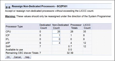
Figure 9-3 Reassign Non-Dedicated Processors results
|
Important: Consider the results of these changes relative to the operational environment. Understand the potential impact of making such operational changes. Changes to the PU assignment, although technically correct, can result in constraints for critical system images. In certain cases, the solution might be to defer the reassignments to another time that might have less impact on the production system images.
|
After you review the reassignment results and make any necessary adjustments, click OK.
The final results of the reassignment, which include the changes that are made as a result of the review, are displayed, as shown in Figure 9-4. These results are the assignments when the drawer removal phase of the EDA is completed.
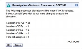
Figure 9-4 Reassign Non-Dedicated Processors, message ACT37294
Summary of the drawer removal process steps
To remove a drawer, the following resources must be moved to the remaining active drawers:
•PUs: Enough PUs must be available on the remaining active drawers, including all types of PUs that can be characterized (CPs, IFLs, ICFs, zIIPs, the IFP2, and SAPs).
•Memory: Enough installed memory must be available on the remaining active drawers.
•I/O connectivity: Alternative paths to other drawers must be available on the remaining active drawers, or the I/O path must be taken offline.
By understanding both the system configuration and the LPAR allocation for memory, PUs, and I/O, you can make the best decision about how to free necessary resources and allow for drawer removal.
To replace concurrently a drawer, complete these steps:
1. Run the preparation task to determine the necessary resources.
2. Review the results.
3. Determine the actions to perform to meet the required conditions for EDA.
4. When you are ready for the drawer removal, free the resources that are indicated in the preparation steps.
5. Rerun the step in Figure 9-1 on page 368 (the Prepare for Enhanced Drawer Availability task) to ensure that the required conditions are all satisfied.
6. Upon successful completion, the system is ready for the removal of the drawer.
The preparation process can be run multiple times to ensure that all conditions are met. It does not reallocate any resources. It only produces a report. The resources are not reallocated until the Perform Drawer Removal process is started.
Rules during EDA
During EDA, the following processor, memory, and single I/O rules are enforced:
•Processor rules
All processors in any remaining drawers are available to be used during EDA. This requirement includes the two spare PUs or any available PU that is non-LICCC.
The EDA process also allows conversion of one PU type to another PU type. One example is converting a zIIP to a CP during the EDA function. The preparation for the concurrent drawer replacement task indicates whether any SAPs must be moved to the remaining drawers.
•Memory rules
All physical memory that is installed in the system, including flexible memory, is available during the EDA function. Any physical installed memory, whether purchased or not, is available to be used by the EDA function.
•Single I/O rules
Alternative paths to other drawers must be available, or the I/O path must be taken offline.
Review the results. The result of the preparation task is a list of resources that must be made available before the drawer replacement can take place.
Freeing any resources
At this stage, create a plan to free these resources. The following list shows the resources and actions that are necessary to free them:
•To free any PUs:
– Vary off the CPs by using the Perform a Model Conversion window, which reduces the number of CPs in the shared CP pool.
– Deactivate the LPARs.
•To free memory:
– Deactivate an LPAR.
– Vary offline a portion of the reserved (online) memory. For example, in z/OS, run the following command:
CONFIG_STOR(E=1),<OFFLINE/ONLINE>
This command enables a storage element to be taken offline. The size of the storage element depends on the RSU value. In z/OS, the following command configures offline smaller amounts of storage than the amount that was set for the storage element:
CONFIG_STOR(nnM),<OFFLINE/ONLINE>
– A combination of both LPAR deactivation and varying memory offline.
|
Reserved storage: If you plan to use the EDA function with z/OS LPARs, set up reserved storage and an RSU value. Use the RSU value to specify the number of storage units that are to be kept free of long-term fixed storage allocations. This configuration allows for storage elements to be varied offline.
|
9.9 z13 Enhanced Driver Maintenance (EDM)
EDM is one more step toward reducing both the necessity for and the duration of a scheduled outage. One of the components to planned outages is LIC Driver updates that are run in support of new features and functions.
When correctly configured, the z13 supports concurrently activating a selected new LIC Driver level. Concurrent activation of the selected new LIC Driver level is supported only at specific released sync points. Concurrently activating a selected new LIC Driver level anywhere in the maintenance stream is not possible. There are certain LIC updates where a concurrent update/upgrade might not be possible.
Consider the following key points of EDM:
•The HMC can query whether a system is ready for a concurrent driver upgrade.
•Previous firmware updates, which require an initial machine load (IML) of z13 to be activated, can block the ability to run a concurrent driver upgrade.
•An icon on the Support Element (SE) allows you or your IBM SSR to define the concurrent driver upgrade sync point to be used for an EDM.
•The ability to concurrently install and activate a driver can eliminate or reduce a planned outage.
•The z13 introduces Concurrent Driver Upgrade (CDU) cloning support to other CPCs for CDU preinstallation and activation.
•Concurrent crossover from Driver level N to Driver level N+1, and to Driver level N+2, must be done serially. No composite moves are allowed.
•Disruptive upgrades are permitted at any time, and allow for a composite upgrade (Driver N to Driver N+2).
•Concurrently backing up to the previous driver level is not possible. The driver level must move forward to driver level N+1 after EDM is initiated. Unrecoverable errors during an update can require a scheduled outage to recover.
The EDM function does not eliminate the need for planned outages for driver-level upgrades. Upgrades might require a system level or a functional element scheduled outage to activate the new LIC. The following circumstances require a scheduled outage:
•Specific complex code changes might dictate a disruptive driver upgrade. You are alerted in advance so that you can plan for the following changes:
– Design data or hardware initialization data fixes
– CFCC release level change
•OSA CHPID code changes might require CHPID Vary OFF/ON to activate new code.
•Changes to the code of native PCIe features might require additional action from the client if the specific feature must be offline to the connecting LPARs before the new code can be applied and brought back online later.
•In changes to the Resource Group (RG) code, all native PCIe features within that RG might need to be varied offline to all connection LPARs by the client and back online after the code is applied.
z13 introduces the support to activate concurrently an MCL on an OSA-ICC channel to improve the availability and simplification of the firmware maintenance. The OSD channels already have this capability.
9.10 RAS capability for the HMC and SE
The HMC and the SE have the following RAS capabilities:
•Back up from HMC and SE
On a scheduled basis, the HMC hard disk drive (HDD) is backed up to the USB flash memory drive (UFD), a customer provided FTP server, or both.
SE HDDs are backed up on to the primary SE HDD and alternate SE HDD. In addition, you can save the backup to a customer-provided FTP server.
For more information, see 11.2.3, “New backup options of HMCs and primary SEs” on page 417.
•Remote Support Facility (RSF)
The HMC RSF provides the important communication to a centralized IBM support network for hardware problem reporting and service. For more information, see 11.4, “Remote Support Facility (RSF)” on page 425.
•Microcode Change Level (MCL)
Regular installation of MCLs is key for RAS, optimal performance, and new functions. Generally, plan to install MCLs quarterly at a minimum. Review hiper MCLs continuously. You must decide whether to wait for the next scheduled apply session, or schedule one earlier if your risk assessment of hiper MCLs warrants.
For more information, see 11.5.4, “HMC and SE microcode” on page 430.
•Support Element (SE)
The z13 is provided with two 1U System x servers inside the z Systems frame. One is always the primary SE and the other is the alternate SE. The primary SE is the active one. The alternate acts as the backup. Once per day, information is mirrored. The SE servers have N+1 redundant power supplies.
For more information, see 11.2.2, “New Support Elements” on page 417.
•Hardware Management Console (HMC) in an ensemble
The serviceability function for the components of an ensemble is delivered through the traditional HMC/SE constructs, as for earlier z Systems systems. From a serviceability point of view, all the components of the ensemble, including the zBX, are treated as z13 features. The zBX receives all of its serviceability and problem management through the HMC and SE infrastructure. All service reporting, including RSF functions, is delivered in a similar fashion to the z13.
The primary HMC for the ensemble is where portions of the Unified Resource Manager routines run. The Unified Resource Manager is an active part of the ensemble and z13 infrastructure. Therefore, the HMC is in a stateful state that needs high availability features to ensure the survival of the system if there is a failure. Therefore, each ensemble must be equipped with two HMCs: A primary and an alternate. The primary HMC performs all HMC activities (including Unified Resource Manager activities). The alternate is only the backup. The alternate cannot be used for tasks or activities.
|
Failover: The primary HMC and its alternate must be connected to the same LAN segment. This configuration allows the alternate HMC to take over the IP address of the primary HMC during failover processing.
|
For more information, see 11.6, “HMC in an ensemble” on page 446.
•Alternate HMC preload function
The Manage Alternate HMC task allows you to reload internal code onto the alternate HMC to minimize HMC downtime during an upgrade to a new driver level. After the new driver is installed on the alternate HMC, it can be made active by running an HMC switchover.
9.11 RAS capability for zBX Mod 004
The zBX Mod 004 exists only as a result of an MES from a zBX Model 002 or zBX Model 003. The zBX Model 004 is now a stand-alone node that contains its own monitoring and controlling SEs. The two new 1U rack-mounted server SEs, along with their displays and keyboards, are added to the stand-alone zBX Model 004 frame B, below the top-of-rack (TOR) switches. zBX Model 004 includes all the RAS capabilities that are available in the previous models, and it was built with the traditional z Systems quality of service (QoS) to include RAS capabilities. The zBX Mod 004 offering provides extended service capability independent of the z13 hardware management structure.
zBX Model 004 is a stand-alone box that can be added to an existing ensemble HMC as an individual ensemble member. The zBX Model 004 is now an object that is required to be defined to the HMC. The ensemble HMC is used to run the zBX configuration and monitoring functions by using its connectivity to its internal SEs.
Apart from a zBX configuration with one chassis that are installed, the zBX is configured to provide N + 1 components. All the components are designed to be replaced concurrently. In addition, zBX configuration upgrades can be performed concurrently.
The zBX has two ToR switches. These switches provide N + 1 connectivity for the private networks between the zBX and its internal support elements for monitoring, controlling, and managing the zBX components.
BladeCenter components
Each BladeCenter has the following components:
•Up to 14 blade server slots. Blades can be removed, repaired, and replaced concurrently.
•(N + 1) PDUs. If the Power Distribution Units (PDUs) have power inputs from two separate sources, if there is a single source failure, the second PDU takes over the total load of its BladeCenter.
•(N + 1) hot-swap power module with fan. A pair of power modules provides power for seven blades. A fully configured BladeCenter with 14 blades has a total of four power modules.
•(N + 1) 1 GbE switch modules for the power system control network (PSCN).
•(N + 1) 10 GbE High Speed switches for the intraensemble data network (IEDN).
•(N + 1) 1000BaseT switches for the intranode management network (INMN).
•(N + 1) 8 Gb FC switches for the external disk.
•(N+1) Internal 1U rack-mounted SEs with fully redundant (N+1) components.
•Two hot-swap advanced management modules (AMMs).
•Two hot-swap fans/blowers.
|
Maximums: Certain BladeCenter configurations do not physically fill up the rack with their components, but they might have reached other maximums, such as power usage.
|
zBX firmware
The testing, delivery, installation, and management of the zBX firmware is handled in the same way as the z13. The same processes and controls are used. All fixes to the zBX are downloaded to the zBX Model 004 internal SEs and applied to the zBX.
The MCLs for the zBX are designed to be concurrent and their status can be viewed at the z13 HMC.
zBX RAS and the IBM z Unified Resource Manager
The Hypervisor Management function of the Unified Resource Manager provides tasks for managing the hypervisor lifecycle, managing storage resources, performing RAS and using the first-failure data capture (FFDC) features, and monitoring the supported hypervisors.
For blades that are deployed in a solution configuration, such as DataPower, the solution handles the complete end-to-end management for them and for their operating systems, middleware, and applications.
For blades that are deployed by the client, the Unified Resource Manager handles the blades:
•The client must have an entitlement for each blade in the configuration.
•When the blade is deployed in the BladeCenter chassis, the Unified Resource Manager powers up the blade, verifies that there is an entitlement for the blade, and verifies that the blade can participate in an ensemble. If these two conditions are not met, the Unified Resource Manager powers down the blade.
•The blade is populated with the necessary microcode and firmware.
•The appropriate hypervisor is loaded onto the blade.
•The management scope is deployed according to which management enablement level is present in the configuration.
•The administrator can define the blade profile, and the profiles for virtual servers to run on the blade, through the HMC.
Based on the profile for individual virtual servers inside the deployed hypervisor, the virtual servers can be activated and an operating system can be loaded following the activation. For client-deployed blades, all of the application, database, operating system, and network management is handled by the client’s usual system management disciplines.
zBX Model 004: 2458-004
The z13 in an ensemble that only supports a zBX Model 004. When upgrading a z196 or a zEC12 to z13, the zBX must also be upgraded from a Model 002 or a Model 003 to a zBX Model 004.
The zBX Model 004 is based on the BladeCenter and blade hardware offerings that contain IBM certified components. zBX Model 004 BladeCenter and blade RAS features are extended considerably for IBM System z®:
•Hardware redundancy at various levels:
– Redundant power infrastructure
– Redundant power and switch units in the BladeCenter chassis
– Redundant cabling for management of zBX and data connections
– Redundant 1U rack-mounted support elements
•Concurrent to system operations:
– Install more blades
– Hardware repair
– Firmware fixes and driver upgrades
– Automated call home for hardware/firmware problems
|
Important: Depending on the type of hardware repair being performed and the firmware fixes being installed or activated, a deactivation of a target blade might be required.
|
The zBX has two pairs of ToR switches, the INMN N+1 pair and the IEDN N+1 switch pair, which are installed in Frame B. The management switch pair (INMN) provides N+1 connectivity for the private networks between the internal zBX support elements SEs and the zBX hardware. The connection is used for monitoring, controlling, and managing the zBX components. The data switch pair (IEDN) provides N+1 connectivity for the data traffic between the defined virtual servers and client’s networks.
Because of the MES conversion from previous zBX Models, a zBX Model 004 became a stand-alone box, independent of the z13 for management and control functions. The zBX Model 004 internal SEs are used for used for firmware updates and other related service activities. Therefore, the distance restriction of 23 meters from the CPC to the zBX that existed with the previous models was removed.
Not only hardware and firmware provide RAS capabilities. The operating system can also contribute to improving RAS. IBM PowerHA® SystemMirror® for AIX (PowerHA) supports the zBX PS701 blades.3 PowerHA enables setting up a PowerHA environment on the stand-alone zBX. Table 9-5 provides more information about PowerHA and the required AIX4 levels that are needed for a PowerHA environment on zBX.
Table 9-5 PowerHA and required AIX levels
|
IBM zBX Model 004
|
AIX V6.1
|
AIX V7.1
|
|
PowerHA V6.1
|
AIX V6.1 TL05
RSCT 2.5.5.0
|
PowerHA V6.1
SP3
AIX V7.1
RSCT V3.1.0.3
|
|
PowerHA V7.1
|
AIX V6.1 TL06
RSCT V3.1.0.3
|
AIX V7.1
RSCT V3.1.0.3
|
zBX Model 004 includes major firmware changes in almost all areas compared to the zBX Model 003. zBX Model 004 takes the RAS concept of the zBX to higher levels.
9.12 Considerations for PowerHA in zBX environment
An application that runs on AIX can be provided with high availability by using the PowerHA SystemMirror for AIX (formerly known as IBM HACMP™5). PowerHA is easy to configure because it is menu-driven, and provides high availability for applications that run on AIX.
PowerHA helps define and manage resources that are required by applications that run on AIX. It provides service/application continuity through system resources and application monitoring, and automated actions (start/manage/monitor/restart/move/stop).
|
Tip: Resource movement and application restart on the second server are known as failover.
|
Automating the failover process speeds up recovery and allows for unattended operations, improving application availability. In an ideal situation, an application must be available 24 x 7. Application availability can be measured as the amount of time that the service is available, divided by the amount of time in a year, as a percentage.
A PowerHA configuration (also known as a cluster) consists of two or more servers6 (up to 32) that have their resources managed by PowerHA cluster services. The configuration provides automated service recovery for the applications that are managed. Servers can have physical or virtual I/O resources, or a combination of both.
PowerHA performs the following functions at the cluster level:
•Manage and monitor operating system and hardware resources.
•Manage and monitor application processes.
•Manage and monitor network resources (service IP addresses).
•Automate application control (start/stop/restart/move).
The virtual servers that are defined and managed in zBX use only virtual I/O resources. PowerHA can manage both physical and virtual I/O resources (virtual storage and virtual network interface cards).
PowerHA can be configured to perform automated service recovery for the applications that run in virtual servers that are deployed in zBX. PowerHA automates application failover from one virtual server in an IBM System p® blade to another virtual server in a different System p blade with a similar configuration.
Failover protects service (masks service interruption) in an unplanned or planned (scheduled) service interruption. During failover, you might experience a short service unavailability while resources are configured by PowerHA on the new virtual server.
The PowerHA configuration for the zBX environment is similar to standard Power environments, except that it uses only virtual I/O resources. Currently, PowerHA for zBX support is limited to fail over inside the same ensemble. All zBXs participating in the PowerHA cluster must have access to the same storage.
The PowerHA configuration includes the following tasks:
•Network planning (VLAN and IP configuration definition and for server connectivity)
•Storage planning (shared storage must be accessible to all blades that provide resources for a PowerHA cluster)
•Application planning (start/stop/monitoring scripts and operating system, processor, and memory resources)
•PowerHA software installation and cluster configuration
•Application integration (integrating storage, networking, and application scripts)
•PowerHA cluster testing and documentation
A typical PowerHA cluster is shown in Figure 9-5.

Figure 9-5 Typical PowerHA cluster diagram
For more information about IBM PowerHA SystemMirror for AIX, see this website:
9.13 IBM z Advanced Workload Analysis Reporter
IBM z Advanced Workload Analysis Reporter (IBM zAware) provides a solution for detecting and diagnosing anomalies in z/OS systems by analyzing software logs and highlighting abnormal events. It represents a first in a new generation of “smart monitoring” products with pattern-based message analysis.
IBM zAware runs as a firmware virtual appliance in a z13 LPAR. It is an integrated set of analytic applications that creates a model of normal system behavior that is based on prior system data. It uses pattern recognition techniques to identify unexpected messages in current data from the z/OS or Linux on z Systems systems that it is monitoring. This analysis of events provides nearly real-time detection of anomalies. These anomalies can then be easily viewed through a graphical user interface (GUI).
|
Statement of Direction1: IBM intends to deliver IBM zAware support for z/VM. This future release of IBM zAware is intended to help identify unusual behaviors of workloads running on z/VM, accelerate problem determination, and improve service levels.
|
1 All statements regarding IBM plans, directions, and intent are subject to change or withdrawal without notice. Any reliance on these statements of general direction is at the relying party’s sole risk and will not create liability or obligation for IBM.
IBM zAware improves the overall RAS capability of z13 by providing these advantages:
•Identify when and where to look for a problem
•Drill down to identify the cause of the problem
•Improve problem determination in near real-time
•Reduce problem determination efforts significantly
For more information about IBM zAware, see Appendix A, “IBM z Advanced Workload Analysis Reporter (IBM zAware)” on page 467.
9.14 RAS capability for Flash Express
Flash Express cards come in pairs for availability, and are exclusively in PCIe I/O drawers. Similar to other PCIe I/O cards, redundant PCIe paths to Flash Express cards are provided by redundant IO interconnect. Unlike other PCIe I/O cards, they can be accessed only by the host by using a unique protocol.
In each Flash Express card, data is stored in four solid-state drives (SSDs) in a RAID configuration. If an SSD fails, the data is reconstructed dynamically. The cards in a pair mirror each other over a pair of cables, in a RAID 10 configuration. If either card fails, the data is available on the other card. Card replacement is concurrent, and does not cause disruption to your operations.
The data is always stored encrypted with a volatile key, and the card is usable only on the system with the key that encrypted it. For key management, both the Primary and Alternate SEs have a smart card reader installed.
Flash Express cards support concurrent firmware upgrades.
Figure 9-6 shows the various components that support Flash Express RAS functions.

Figure 9-6 Flash Express RAS components
For more information about Flash Express, see Appendix C, “Flash Express” on page 489.
1 Some pre-planning considerations might exist. For more information, see Chapter 8, “System upgrades” on page 307.
2 If any native PCIe features are installed on the system.
3 PS701 8406-71Y blades.
4 AIX 6.1 Technology Level (TL)06 Service Pack (SP) 3 with RSCT 3.1.0.4 (packaged in Cluster Systems Management (CSM) PTF 1.7.1.10 installed with AIX 6.1.6.3) is the preferred baseline for zBX Virtual Servers running AIX.
5 High Availability Cluster Multi-Processing.
6 Servers can be also virtual servers. One server is one instance of the AIX operating system.
..................Content has been hidden....................
You can't read the all page of ebook, please click here login for view all page.