


Central processor complex (CPC) hardware components
This chapter introduces IBM z13 (z13) CPC hardware components. It also describes the significant features and functions with their characteristics and options. The objective is to explain the z13 hardware building blocks and how these components interconnect from a physical point of view. This information is useful for planning purposes and can help in defining configurations that fit your requirements.
This chapter includes the following sections:
2.1 Frames and drawers
z Systems frames are enclosures that are built to Electronic Industries Alliance (EIA) standards. The z13 has two 42U EIA frames. The two frames, A and Z, are bolted together and have positions for up to four CPC drawers and a combination of Peripheral Component Interconnect Express (PCIe) I/O drawers, and I/O drawers carried forward from an older system. The other components included in the frames are explained in the following sections.
z13 and its predecessor, the zEC12, have the option of ordering the infrastructure to support the top exit of fiber optic cables (FICON, OSA, 12x InfiniBand, 1x InfiniBand, ICA SR, and RoCE) and copper cables for the 1000BASE-T Ethernet features. On the z13, the top exit capability is designed to provide an option for overhead power cabling.
The z13 can be delivered as an air-cooled system or as a water-cooled system. A picture of an air-cooled system with the optional top exit I/O and power feature is shown in Figure 2-1, with the maximum of four CPC drawers and five PCIe I/O drawers.

Figure 2-1 z13 internal front view of an air-cooled CPC (models NC9 or NE1)
A picture of a water-cooled system without the optional top exit I/O and power feature is shown in Figure 2-2, with the maximum of four CPC drawers and five PCIe I/O drawers.

Figure 2-2 z13 internal front view of a water-cooled CPC (models NC9 or NE1)
2.1.1 A Frame
As shown in Figure 2-1 on page 30 and Figure 2-2, the A frame has the following major components (from top to bottom of the frame):
•Two Support Element (SE) servers that are installed at the top of the A frame. In previous z Systems, the SEs were notebooks in the Z Frame. For z13, the SEs are replaced with the 1U servers, which are mounted at the top of the 42U EIA frame.
•Two optional integrated battery features (IBFs), which provide the function of a local uninterrupted power source. The IBF enhances the robustness of the power design, increasing power line disturbance immunity.
•One PCIe I/O drawer. The presence of this PCIe I/O drawer depends on the I/O configuration of the z13.
•Two System Control Hubs (SCH). The SCHs are the replacement of the Bulk Power Hubs that were used in previous z Systems.
•Up to four CPC drawers. The number of the CPC drawers depends on the model number of the z13. At least one CPC drawer must be installed, and the additional ones are filled up from the bottom to the top.
•The cooling units for the closed loop water-cooling system of the CPC drawers in the bottom of the A Frame differ for air-cooled and water-cooled systems:
a. For an air-cooled z13 (Figure 2-1 on page 30), three pumps and three blowers (N+2 redundant design) are installed.
b. For a water-cooled z13 (Figure 2-2), two Water Conditioning Units (WCUs) are installed. The WCUs are connected to a customer-operated (data center) chilled water supply.
2.1.2 Z Frame
As shown in Figure 2-1 on page 30 and Figure 2-2 on page 31, the Z frame has the following major components (from top to bottom of the frame):
•Two or four optional IIBFs. The number of batteries depends on the number of bulk power regulators that are installed. IBFs are always installed in pairs.
•Bulk power regulators (BPRs). The number of BPRs varies depending on the configuration of the z13. For more information about the required number of BPRs, see 2.8.1, “Power consumption” on page 70.
•The Keyboard and Display tray, which is in front of the I/O drawer slots, contains the keyboard and the display that are connected to the SEs.
•Up to four drawers, which can be any combination of up to two I/O drawers and up to four PCIe I/O drawers:
– The PCIe I/O drawer is used for all new installations or can be carried forward through miscellaneous equipment specification (MES).
– The I/O drawer itself can be carried forward only with an MES from z196 or zEC12.
•An optional overhead power cable feature is shown in Figure 2-1 on page 30. When this feature is ordered, it is present on the Z frame. The top I/O exit cabling feature also must be installed in this case.
2.1.3 z13 new rear cover (door) design
The new design of the rear door covers addresses data center airflow challenges. You can change the cover (door) fins orientation down or up, as shown in Figure 2-3. This design directs the hot air that is exhausted by z13 to avoid adversely affecting cooling of other systems on the hot isle.

Figure 2-3 Rear cover vectored air output
2.1.4 I/O drawer and PCIe I/O drawer
Each CPC drawer has 10 PCIe Generation3 fanout slots and four InfiniBand fanout slots to support two types of I/O infrastructure for data transfer:
•PCIe I/O infrastructure with a bandwidth of 16 GBps
•InfiniBand I/O infrastructure with a bandwidth of 6 GBps
PCIe I/O infrastructure
The PCIe I/O infrastructure uses the PCIe fanout to connect to the PCIe I/O drawer, which can contain the following features:
•FICON Express16S (two port card, long wavelength (LX) or short wavelength (SX), and two channel-path identifiers (CHPIDs)).
•FICON Express8S (two port card, LX or SX, and two CHPIDs).
•Open System Adapter (OSA)-Express5S features:
– OSA-Express5S 10 Gb Ethernet (one port card, Long Reach (LR) or Short Reach (SR), and one CHPID)
– OSA-Express5S Gb Ethernet (two port card, LX or SX, and one CHPID)
– OSA-Express5S 1000BASE-T Ethernet (two port card, RJ-45, and one CHPID)
•OSA-Express4S features (only for a carry-forward MES):
– OSA-Express4S 10 Gb Ethernet (one port card, LR or SR, and one CHPID)
– OSA-Express4S Gb Ethernet (two port card, LX or SX, and one CHPID)
– OSA-Express4S 1000BASE-T Ethernet (two port card, RJ-45, and one CHPID)
•Crypto Express5S feature. Each feature holds one PCI Express cryptographic adapter. Each adapter can be configured by the installation as a Secure IBM Common Cryptographic Architecture (CCA) coprocessor, as a Secure IBM Enterprise Public Key Cryptography Standards (PKCS) #11 (EP11) coprocessor, or as an accelerator.
•Flash Express. Each Flash Express feature occupies two I/O slots, but does not have a CHPID type. Logical partitions (LPARs) in all channel subsystems (CSSs) have access to the features.
•10 GbE Remote Direct Memory Access (RDMA) over Converged Ethernet (RoCE) Express. It has a 2-port card, and up to 31 LPARS can share a physical adapter.
•zEnterprise Data Compression (zEDC) Express. The zEnterprise Data Compression Express feature occupies one I/O slot, but it does not have a CHPID type. Up to 15 partitions can share the feature concurrently.
InfiniBand I/O infrastructure
InfiniBand I/O infrastructure uses the HCA2-C fanout to connect to I/O drawers. The I/O drawers can contain only FICON Express8 cards (four port card, LX or SX, and four CHPIDs).
2.1.5 Top exit I/O cabling
Like the zEC12, the z13 supports the Top Exit I/O Cabling feature (FC 7942). This feature routes all coupling links and all I/O cables, including a 1000BASE-T Ethernet cable from I/O drawers or PCIe I/O drawers through four more frame extensions, out the top of the frame.
Figure 2-4 shows the frame extensions, also called chimneys, that are installed to each corner of the frames (A frame and Z frame) when the Top Exit I/O Cabling feature (FC 7942) is ordered. The bottom of the chimney is closed with welded sheet metal.
The Top Exit I/O Cabling feature adds 15 cm (6 in.) to the width of each frame and about 95 lbs (43 kg) to the weight.
In the z13, the Top Exit I/O Cabling feature (FC 7942) is available for both radiator-cooled (air-cooled) models and water-cooled models.

Figure 2-4 Top Exit I/O cabling feature
2.2 CPC drawer
The z13 central processor complex (CPC) has been redesigned to package processors in drawers, unlike the books that are used in zEC12 machines. A z13 CPC drawer contains eight single chip modules (SCM), memory, SMP connectivity, and connectors to support PCIe I/O drawers (through PCIe fanout hubs), I/O drawers through InfiniBand features, and coupling links to other CPCs. The CPC drawers are in the A frame. The z13 can have up to four CPC drawers installed (the minimum is one drawer). A CPC drawer and its components are shown in Figure 2-5.

Figure 2-5 CPC drawer components (top view)
The CPC drawer is divided in to two nodes. Each node contains the following components:
•Three 8-core processor unit (PU) SCMs, with six, seven, or eight active cores, depending on the machine model.
•One storage controller SCM, with a 480 MB L4 cache.
•Five DDR3 DIMM slots per memory controller, for a total of 15 per node.
Each CPC drawer contains two nodes, which altogether consist of the following components:
•Six 8-core PU SCMs, with 39 or 42 active PUs, depending on the model.
•Two Storage Controller SCMs, with 960 MB L4 cache total.
•Dual in-line memory modules (DIMMs) plugged in to 20 or 25 DIMM slots of the total of 30 DIMM slots available, providing 320 - 3,200 GB of physical memory and 256 - 2,560 GB of addressable (customer available) memory.
•Ten PCIe Generation 3 (PCIe Gen3) slots for PCIe I/O drawer fanouts or PCIe coupling links fanouts.
•Four GX++ slots for IFB fanouts or InfiniBand coupling fanouts.
•Two flexible service processor (FSP) cards for system control.
•Four DC converter assemblies (DCAs) that provide power to the CPC drawer. Loss of one DCA leaves enough power to satisfy the drawer’s power requirements (n+1 redundancy). The DCAs can be concurrently removed and replaced (one at a time).
•Water-cooling manifold for PU chips.
Figure 2-6 shows the front view of a CPC drawer, with fanouts slots and connector for water cooling, and the rear view of drawer, with the DIMM slots and DCA connector.

Figure 2-6 Front and rear view of the CPC drawer
Figure 2-7 shows the CPC drawer logical structure, component connections (including the PU SCMs), and the SC SCMs.

Figure 2-7 CPC drawer logical structure
Memory is connected to the SCMs through memory control units (MCUs). There are six MCUs in a drawer, one per PU SCM, that provide the interface to controller on memory DIMM. A memory controller drives five DIMM slots.
The buses are organized as follows:
•The GX++ I/O bus slots provide connectivity for host channel adapters (HCAs). They are fully buffered, and can sustain up to 6 GBps data transfer per bus direction. GXX++ I/O slots provide support for InfiniBand and non-PCIe I/O features (FICON Express 8).
•The PCIe I/O buses provide connectivity for PCIe fanouts and can sustain up to 16 GBps data traffic per bus direction.
•The X-bus provides interconnects between SC chip and PUs chips to each other, in the same node.
•The S-bus provides interconnects between SCs chips in the same drawer.
•The A-bus provides interconnects between SCs chips in different drawers (through SMP cables).
•Processor support interfaces (PSIs) are used to communicate with FSP cards for system control.
2.2.1 CPC drawer interconnect topology
Figure 2-8 shows the point-to-point topology for CPC drawers and nodes communication. Each CPC drawer communicates directly to all others processors drawers in the CPC through two ways.

Figure 2-8 Drawer to drawer communication
The CPC drawers are in the Frame A and are populated from bottom to top.
Table 2-1 indicates the order of CPC drawers installation and position in the Frame A.
Table 2-1 CPC drawers installation order and position in Frame A
|
CPC drawer
|
CPC drawer 0
|
CPC drawer 1
|
CPC drawer 2
|
CPC drawer 3
|
|
Installation order
|
First
|
Second
|
Third
|
Fourth
|
|
Position in Frame A
|
A15A
|
A19A
|
A23A
|
A27A
|
CPC drawer installation is concurrent, except for the upgrade to the model NE1, which requires complete replacement of all four drawers. Concurrent drawer repair requires a minimum of two drawers.
2.2.2 Oscillator
The z13 has two oscillator cards (OSCs): One primary and one backup. If the primary OSC fails, the secondary detects the failure, takes over transparently, and continues to provide the clock signal to the CPC. The two oscillators have BNC connectors that provide pulse per second signal (PPS) synchronization to an external time source (a Network Time Protocol (NTP) server with PPS output).
The SEs provide the Simple Network Time Protocol (SNTP) client function. When Server Time Protocol (STP) is used, the time of an STP-only Coordinated Timing Network (CTN) can be synchronized to the time that is provided by an NTP server. This configuration allows time-of-day (TOD) synchronization in a heterogeneous platform environment.
The accuracy of an STP-only CTN is improved by using an NTP server with the PPS output signal as the external time source (ETS). NTP server devices with PPS output are available from several vendors that offer network timing solutions. A cable connection from the PPS port on the OSC to the PPS output of the NTP server is required when the zNext is using STP and is configured in an STP-only CTN using NTP with PPS as the external time source. The z13 cannot participate in a mixed CTN: It can participate only in an STP only CTN.
STP tracks the highly stable and accurate PPS signal from the NTP server and maintains an accuracy of 10 µs to the ETS, as measured at the PPS input of the IBM z13.
If STP uses an NTP server without PPS, a time accuracy of 100 ms to the ETS is maintained.
Although not part of the CPC drawer design, the OSCs cards are located beside the drawers, and are connected to the same backplane to which the drawers are connected. All four drawers connect to the OSC.
Figure 2-9 shows the location of the two OSC cards with BNC connectors for PPS on the CPC, which is beside the drawer 2 and drawer 3 locations.

Figure 2-9 Oscillators cards
|
Tip: STP is available as FC 1021. It is implemented in the Licensed Internal Code (LIC), and allows multiple servers to maintain time synchronization with each other and synchronization to an ETS. For more information, see the following publications:
•Server Time Protocol Planning Guide, SG24-7280
•Server Time Protocol Implementation Guide, SG24-7281
•Server Time Protocol Recovery Guide, SG24-7380
|
2.2.3 System control
Various system elements are managed through the flexible service processors (FSPs). An FSP is based on the IBM PowerPC® microprocessor technology. Each FSP card has two ports to connects to two internal Ethernet LANs, through system control hubs (SCH1 and SCH2). The FSPs communicate with the SEs and provide a subsystem interface (SSI) for controlling components.
Figure 2-10 is a conceptual overview of the system control design.

Figure 2-10 Conceptual overview of system control elements
A typical FSP operation is to control a power supply. An SE sends a command to the FSP to start the power supply. The FSP (using SSI connections) cycles the various components of the power supply, monitors the success of each step and the resulting voltages, and reports this status to the SE.
Most system elements are duplexed (n+1), and each element has at least one FSP. Two internal Ethernet LANs and two SEs, for redundancy, and crossover capability between the LANs, are available so that both SEs can operate on both LANs.
The SEs, in turn, are connected to one or two (external) LANs (Ethernet only), and the Hardware Management Consoles (HMCs) are connected to these external LANs. One or more HMCs can be used, but two (a primary and an alternate) are mandatory with an ensemble. Extra HMCs can operate a z13 when the CPC is not a member of an ensemble. For more information, see 11.6, “HMC in an ensemble” on page 446
2.2.4 CPC drawer power
Each CPC drawer gets its power from two DCAs. The DCAs provide the required power for the drawer in an n+1 configuration. Loss of one DCA leaves enough power to meet power requirements for the entire drawer. The DCAs can be concurrently maintained, and are accessed from the rear of the frame A.
Figure 2-11 shows the location of DCAs on the backplane of the A frame.
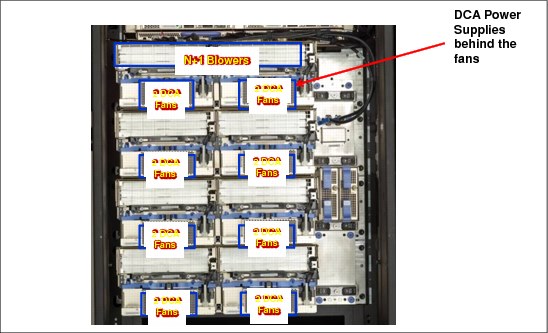
Figure 2-11 DCA power supplies
2.3 Single chip modules (SCMs)
The SCM is a multi-layer metal substrate module that holds either one PU chip or a storage control (SC) chip. Its size is 678.76 mm2 (28.4 mm x 23.9 mm). Each node of a CPC drawer has four SCMs, three PU SCMs, and one SC SCM. Each CPC drawer has eight SCMs, six PU SCMs, and two SC SCMs, with more than 38 billion transistors in total.
The two types of SCMs (PU and SC) are shown in Figure 2-12.
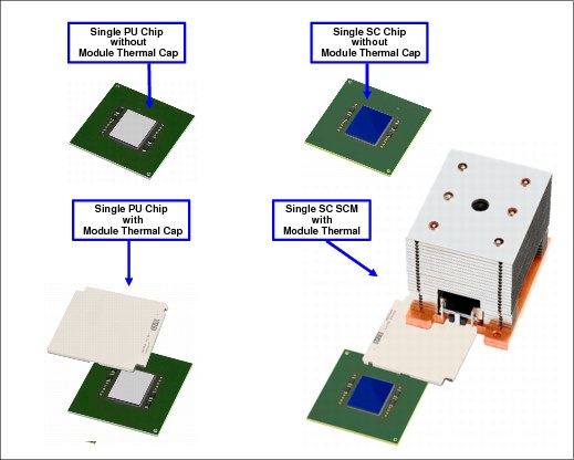
Figure 2-12 Single chip modules (PU SCM and SC SCM)
Both PU and SC chips use CMOS 14S0 process state-of-the-art semiconductor technology, which is implemented with 17-layer (PU chip) or 15-layer (SC chip) copper interconnections and Silicon-On-Insulator (SOI) technologies. The chip lithography line width is 22 nm.
The SCMs are plugged into a card that is part of the CPC drawer packaging. The interconnectivity between the CPC drawers is accomplished through SMP connectors and cables. There are three inter-drawer connections on each node of the CPC drawer. This configuration allows a multidrawer system to be displayed as a symmetric multiprocessor (SMP) system.
Each node has four SCMs: Three PU SCMs and one SC SCM. Figure 2-13 depicts the node structure diagram, showing the PUs and SCs and their connections.

Figure 2-13 PU and SC chips node-drawer structure
2.3.1 Processor unit (PU) chip
The z13 PU chip (installed as a PU SCM) is an evolution of the zEC12 core design. It uses CMOS 14S0 technology, out-of-order instruction processing, pipeline enhancements, dynamic simultaneous multithreading (SMT), single-instruction multiple-data (SIMD), and redesigned and larger caches.
Each PU chip has up to eight cores that run at 5.0 GHz, which means that the cycle time is 0.2 ns. The PU chips come in three versions: Six, seven, and eight active cores. For models N30, N63, N96, and NC9, the processor units in each drawer are implemented with 39 active cores per drawer. This configuration means that model N30 has 39, model N63 has 78, model N96 has 117, and model NC9 has 156 active cores.
Model NE1 has 42 active cores per drawer. This configuration means that there are 168 active cores on model NE1. A schematic representation of the PU chip is shown in Figure 2-14.

Figure 2-14 PU chip (PU SCM) diagram
Each PU chip has 3.99 billion transistors. Each one of the eight cores has its own L1 cache with 96 KB for instructions and 128 KB for data. Next to each core is its private L2 cache, with 2 MB for instructions and 2 MB for data.
Each PU chip has one L3 cache, with 64 MB. This 64 MB L3 cache is a store-in shared cache across all cores in the PU chip. It has 192 x 512 KB eDRAM macros, dual address-sliced and dual store pipe support, an integrated on-chip coherency manager, cache, and cross-bar switch. The L3 directory filters queries from the local L4. Both L3 slices can deliver up to 16 GBps bandwidth to each core simultaneously. The L3 cache interconnects the eight cores, GX++ I/O buses, PCIe I/O buses, and memory controllers (MCs) with storage control (SC) chips.
The MC function controls access to memory. The GX++ I/O bus controls the interface to the HCAs accessing the I/O. The chip controls traffic between the cores, memory, I/O, and the L4 cache on the SC chips.
One coprocessor (CoP) is dedicated for data compression and encryption functions for each core. The compression unit is integrated with the CP Assist for Cryptographic Function (CPACF), benefiting from combining (or sharing) the use of buffers and interfaces. The assist provides high-performance hardware encrypting and decrypting support for clear key operations.
For more information, see 3.4.5, “Compression and cryptography accelerators on a chip” on page 95.
2.3.2 Processor unit (core)
Each processor unit, or core, is a superscalar and out-of-order processor that has 10 execution units and two load/store units, which are divided into two symmetric pipelines as follows:
•Four fixed-point units (FXUs) (integer)
•Two load/store units (LSUs)
•Two binary floating-point units (BFUs)
•Two binary coded decimal floating-point units (DFUs)
•Two vector floating point units (Vector Execution units or VXUs)
Up to six instructions can be decoded per cycle, and up to 10 instructions/operations can be initiated to run per clock cycle. The running of the instructions can occur out of program order, and memory address generation and memory accesses can also occur out of program order. Each core has special circuitry to display execution and memory accesses in order to the software. Not all instructions are directly run by the hardware, which is the case for several complex instructions. Some are run by millicode, and some are broken into multiple operations that are then run by the hardware.
Each core has the following functional areas, which are also shown in Figure 2-15 on page 46:
•Instruction sequence unit (ISU): This unit enables the out-of-order (OOO) pipeline. It tracks register names, OOO instruction dependency, and handling of instruction resource dispatch.
This unit is also central to performance measurement through a function called instrumentation.
•Instruction fetch and branch (IFB) (prediction) and instruction cache and merge (ICM): These two subunits (IFB and ICM) contain the instruction cache, branch prediction logic, instruction fetching controls, and buffers. The relative size of these subunits is the result of the elaborate branch prediction design, which is described in 3.4.4, “Superscalar processor” on page 94.
•Instruction decode unit (IDU): The IDU is fed from the IFB buffers, and is responsible for the parsing and decoding of all z/Architecture operation codes.
•Load-store unit (LSU): The LSU contains the data cache. It is responsible for handling all types of operand accesses of all lengths, modes, and formats that are defined in the z/Architecture.
•Translation unit (XU): The XU has a large translation lookaside buffer (TLB) and the dynamic address translation (DAT) function that handles the dynamic translation of logical to physical addresses.
•Core pervasive unit - PC: Used for instrumentation and error collection.
•Vector and floating point units:
– Fixed-point unit (FXU): The FXU handles fixed-point arithmetic.
– Binary floating-point unit (BFU): The BFU handles all binary and hexadecimal floating-point and fixed-point multiplication operations.
– Decimal floating-point unit (DFU): The DFU runs both floating-point and decimal fixed-point operations and fixed-point division operations.
– Vector execution unit (VXU)
•Recovery unit (RU): The RU keeps a copy of the complete state of the system that includes all registers, collects hardware fault signals, and manages the hardware recovery actions.
•Dedicated Coprocessor (COP): The dedicated coprocessor is responsible for data compression and encryption functions for each core.

Figure 2-15 Core layout
2.3.3 PU characterization
In each CPC drawer, some PUs can be characterized for client use. The characterized PUs can be used in general to run supported operating systems, such as z/OS, z/VM, and Linux on z Systems. They also can run specific workloads, such as Java, XML services, IPSec, and some DB2 workloads, or functions such as Coupling Facility Control Code (CFCC). For more information about PU characterization, see 3.5, “Processor unit (PU) functions” on page 100.
The maximum number of characterized PUs depends on the z13 model. Some PUs are characterized by the system as standard system assist processors (SAPs) to run the I/O processing. By default, there are at least two spare PUs per system that are used to assume the function of a failed PU. The remaining installed PUs can be characterized for client use. A z13 model nomenclature includes a number that represents the maximum number of PUs that can be characterized for client use, as shown in Table 2-2.
Table 2-2 Number of PUs per z13 model
|
Model / CPC drawers
|
Installed PUs
|
Standard SAPs
|
Minimum spare PUs
|
Maximum characterized PUs
|
Integrated firmware processor (IFP)
|
|
|
N30 / 1
|
39 (1 x 39)
|
6
|
2
|
30
|
1
|
|
|
N63 / 2
|
78 (2 x 39)
|
12
|
2
|
63
|
1
|
|
|
N96 / 3
|
117 (3 x 39)
|
18
|
2
|
96
|
1
|
|
|
NC9 / 4
|
156 (4 x 39)
|
24
|
2
|
129
|
1
|
|
|
NE1 / 4
|
168 (4 x 42)
|
24
|
2
|
141
|
1
|
|
2.3.4 Storage control (SC) chip
The SC chip uses the CMOS 14S0 22 nm SOI technology, with 15 layers of metal. It measures 28.4 x 23.9 mm (), has 7.1 billion transistors, and has 2.1 billion cells of eDRAM. Each node of the CPC drawer has one SC chip. The L4 cache on each SC chip has 480 MB of non-inclusive cache and a 224 MB Non-data Inclusive Coherent (NIC) directory, which results in 960 MB of in on-inclusive L4 cache and 448 MB in a NIC directory that is shared per CPC drawer.
Figure 2-16 shows a schematic representation of the SC chip.

Figure 2-16 SC chip diagram
Most of the SC chip space is taken by the L4 controller and the 480 MB L4 cache. The cache consists of four 120 MB quadrants with 256 x 1.5 MB eDRAM macros per quadrant. The L4 cache is logically organized as 16 address-sliced banks, with 30-way set associative. The L4 cache controller is a single pipeline with multiple individual controllers, which is sufficient to handle 125 simultaneous cache transactions per chip.
The L3 caches on PU chips communicate with the L4 caches through the attached SC chip by using unidirectional buses. L3 is divided into two logical slices. Each slice is 32 MB, and consists of two 16 MB banks. L3 is 16-way set associative. Each bank has 4 K sets, and the cache line size is 256 bytes.
The bus/clock ratio (2:1) between the L4 cache and the PU is controlled by the storage controller on the SC chip.
The SC chip also acts as an L4 cache cross-point switch for L4-to-L4 traffic to up to three remote CPC drawers through three bidirectional data buses. The SMP cables transport and system coherency manager use the L4 directory to filter snoop traffic from remote CPC drawers. This process uses an enhanced synchronous fabric protocol for improved latency and cache management. There are six clock domains, and the clock function is distributed between both SC chips.
2.3.5 Cache level structure
z13 implements a four level cache structure, as shown in Figure 2-17.

Figure 2-17 Cache level structure
Each core has its own 224-KB Level 1 (L1) cache, split into 96 KB for instructions (I-cache) and 128 KB for data (D-cache). The L1 cache is designed as a store-through cache, meaning that altered data also is stored in the next level of memory.
The next level is the Level 2 (L2) private cache on each core. This cache has 4 MB, split into a 2 MB D-cache and 2 MB I-cache. It is designed as a store-through cache.
The Level 3 (L3) cache is also on the PU chip. It is shared by the eight cores, has 64 MB, and is designed as a store-in cache.
Cache levels L2 and L3 are implemented on the PU chip to reduce the latency between the processor and the L4 large shared cache, which is on the two SC chips. Each SC chip has 480 MB, which is shared by PU chips on the node. The S-bus provide the inter-node interface between the two L4 caches (SC chips) in each node. The L4 cache uses a store-in design.
2.4 Memory
The maximum physical memory size is directly related to the number of CPC drawers in the system. Each CPC drawer can contain up to 3,200 GB of physical memory, for a total of 12,800 GB (12.5 TB) of installed (physical) memory per system.
A z13 has more memory that is installed than ordered. Part of the physical installed memory is used to implement the redundant array of independent memory (RAIM) design. This configuration results in up to 2,560 GB of available memory per CPC drawer and up to
10,240 GB (10 TB) per system.
10,240 GB (10 TB) per system.
Table 2-3 shows the maximum and minimum memory sizes that you can order for each z13 model.
Table 2-3 z13 memory sizes
|
Model
|
Number of CPC drawer
|
Customer memory (GB)
|
|
N30
|
1
|
64 - 2464
|
|
N63
|
2
|
64 - 5024
|
|
N96
|
3
|
64 - 7584
|
|
NC9
|
4
|
64 - 10144
|
|
NE1
|
4
|
64 - 10144
|
The minimum physical installed memory is 320 GB per CPC drawer. The minimum initial amount of memory that can be ordered is 64 GB for all z13 models. The maximum customer memory size is based on the physical installed memory minus the RAIM and minus the hardware system area (HSA) memory, which has a fixed amount of 96 GB.
Table 2-4 shows the memory granularity that is based on the installed customer memory.
Table 2-4 Memory granularity
|
Granularity (GB)
|
Customer memory (GB)
|
|
32
|
64 - 192
|
|
64
|
256 - 448
|
|
96
|
448 - 928
|
|
128
|
928 - 1440
|
|
256
|
1440 - 6048
|
|
512
|
6560 - 10144
|
With the z13, the memory granularity varies from 32 GB (for customer memory sizes 64 -192 GB) up to 512 GB (for CPCs having 6560 -10144 GB of customer memory).
2.4.1 Memory subsystem topology
The z13 memory subsystem uses high speed, differential-ended communications memory channels to link a host memory to the main memory storage devices.
Figure 2-18 shows an overview of the CPC drawer memory topology of a z13.

Figure 2-18 CPC drawer memory topology
Each CPC drawer has 20 or 25 DIMMs. DIMMs are connected to each PU chip through the memory controller units (MCUs). Each PU chip has one MCU, which uses five channels, one for each DIMM, and one for RAIM implementation, in a 4 +1 design. Each CPC drawer can have four or five populated MCUs.
Each DIMM has 16 GB, 32 GB, 64 GB, or 128 GB. DIMMs features with different sizes can be mixed in the same CPC drawer, but in the same feature, all five DIMMs have the same size.
2.4.2 Redundant array of independent memory
The z13 uses the RAIM technology. The RAIM design detects and recovers from failures of DRAMs, sockets, memory channels, or DIMMs.
The RAIM design requires the addition of one memory channel that is dedicated for reliability, availability, and serviceability (RAS), as shown in Figure 2-19.

Figure 2-19 RAIM configuration per node
The parity of the four “data” DIMMs is stored in the DIMMs that are attached to the fifth memory channel. Any failure in a memory component can be detected and corrected dynamically. This simplifies the memory subsystem design, while maintaining a fully fault-tolerant RAIM design.
The RAIM design provides the following layers of memory recovery:
•ECC with 90B/64B Reed Solomon code.
•DRAM failure, with marking technology in which two DRAMs can be marked and no half sparing is needed. A call for replacement occurs on the third DRAM failure.
•Lane failure with CRC retry, data-lane sparing, and clock-RAIM with lane sparing.
•DIMM failure with CRC retry, data-lane sparing, and clock-RAIM with lane sparing.
•DIMM controller ASIC failure.
•Channel failure.
2.4.3 Memory configurations
Memory sizes in each CPC drawer do not have to be similar. Different CPC drawers can contain different amounts of memory. Table 2-5 shows the physically installed memory on each CPC drawer for all z13 models.
Table 2-5 Physically installed memory
|
Customer Memory
|
Model N30
|
Model N63
|
Model N96
|
Model NC9 and Model NE1
|
||||||
|
(GB)
|
CPC drawer 0
|
CPC drawer 0
|
CPC drawer 1
|
CPC drawer0
|
CPC drawer1
|
CPC drawer 2
|
CPC drawer 0
|
CPC drawer 1
|
CPC drawer 2
|
CPC drawer 3
|
|
64
|
320
|
320
|
320
|
320
|
320
|
320
|
320
|
320
|
320
|
320
|
|
96
|
320
|
320
|
320
|
320
|
320
|
320
|
320
|
320
|
320
|
320
|
|
128
|
320
|
320
|
320
|
320
|
320
|
320
|
320
|
320
|
320
|
320
|
|
160
|
320
|
320
|
320
|
320
|
320
|
320
|
320
|
320
|
320
|
320
|
|
192
|
480
|
320
|
320
|
320
|
320
|
320
|
320
|
320
|
320
|
320
|
|
256
|
480
|
320
|
320
|
320
|
320
|
320
|
320
|
320
|
320
|
320
|
|
320
|
640
|
320
|
320
|
320
|
320
|
320
|
320
|
320
|
320
|
320
|
|
384
|
640
|
320
|
320
|
320
|
320
|
320
|
320
|
320
|
320
|
320
|
|
448
|
960
|
480
|
320
|
320
|
320
|
320
|
320
|
320
|
320
|
320
|
|
544
|
960
|
480
|
320
|
320
|
320
|
320
|
320
|
320
|
320
|
320
|
|
640
|
960
|
480
|
480
|
320
|
320
|
320
|
320
|
320
|
320
|
320
|
|
736
|
1280
|
640
|
480
|
480
|
320
|
320
|
320
|
320
|
320
|
320
|
|
832
|
1280
|
640
|
640
|
480
|
480
|
320
|
320
|
320
|
320
|
320
|
|
928
|
1280
|
640
|
640
|
480
|
480
|
320
|
320
|
320
|
320
|
320
|
|
1056
|
1920
|
960
|
640
|
480
|
480
|
480
|
480
|
320
|
320
|
320
|
|
1184
|
1920
|
960
|
640
|
640
|
480
|
480
|
480
|
480
|
320
|
320
|
|
1312
|
1920
|
960
|
960
|
640
|
640
|
480
|
480
|
480
|
480
|
320
|
|
1440
|
1920
|
960
|
960
|
640
|
640
|
640
|
480
|
480
|
480
|
480
|
|
1696
|
2560
|
1280
|
960
|
960
|
640
|
640
|
640
|
640
|
480
|
480
|
|
1952
|
2560
|
1280
|
1280
|
960
|
960
|
640
|
640
|
640
|
640
|
640
|
|
2208
|
3200
|
1920
|
1280
|
960
|
960
|
960
|
960
|
640
|
640
|
640
|
|
2464
|
3200
|
1920
|
1280
|
1280
|
960
|
960
|
960
|
960
|
640
|
640
|
|
2720
|
N/A
|
1920
|
1920
|
1280
|
1280
|
960
|
960
|
960
|
960
|
640
|
|
2976
|
N/A
|
1920
|
1920
|
1280
|
1280
|
1280
|
960
|
960
|
960
|
960
|
|
3232
|
N/A
|
2560
|
1920
|
1920
|
1280
|
1280
|
1280
|
1280
|
960
|
960
|
|
3488
|
N/A
|
2560
|
1920
|
1920
|
1280
|
1280
|
1280
|
1280
|
960
|
960
|
|
3744
|
N/A
|
2560
|
2560
|
1920
|
1920
|
1280
|
1280
|
1280
|
1280
|
960
|
|
4000
|
N/A
|
2560
|
2560
|
1920
|
1920
|
1280
|
1280
|
1280
|
1280
|
1280
|
|
4256
|
N/A
|
3200
|
2560
|
1920
|
1920
|
1920
|
1920
|
1280
|
1280
|
1280
|
|
4512
|
N/A
|
3200
|
2560
|
1920
|
1920
|
1920
|
1920
|
1280
|
1280
|
1280
|
|
4768
|
N/A
|
3200
|
3200
|
2560
|
1920
|
1920
|
1920
|
1920
|
1280
|
1280
|
|
5024
|
N/A
|
3200
|
3200
|
2560
|
1920
|
1920
|
1920
|
1920
|
1280
|
1280
|
|
5280
|
N/A
|
N/A
|
N/A
|
2560
|
2560
|
1920
|
1920
|
1920
|
1920
|
1280
|
|
5536
|
N/A
|
N/A
|
N/A
|
2560
|
2560
|
1920
|
1920
|
1920
|
1920
|
1280
|
|
5792
|
N/A
|
N/A
|
N/A
|
2560
|
2560
|
2560
|
1920
|
1920
|
1920
|
1920
|
|
6048
|
N/A
|
N/A
|
N/A
|
2560
|
2560
|
2560
|
1920
|
1920
|
1920
|
1920
|
|
6560
|
N/A
|
N/A
|
N/A
|
3200
|
2560
|
2560
|
2560
|
1920
|
1920
|
1920
|
|
7072
|
N/A
|
N/A
|
N/A
|
3200
|
3200
|
2560
|
2560
|
2560
|
1920
|
1920
|
|
7584
|
N/A
|
N/A
|
N/A
|
3200
|
3200
|
3200
|
2560
|
2560
|
2560
|
1920
|
|
8096
|
N/A
|
N/A
|
N/A
|
N/A
|
N/A
|
N/A
|
2560
|
2560
|
2560
|
2560
|
|
8608
|
N/A
|
N/A
|
N/A
|
N/A
|
N/A
|
N/A
|
3200
|
2560
|
2560
|
2560
|
|
9120
|
N/A
|
N/A
|
N/A
|
N/A
|
N/A
|
N/A
|
3200
|
3200
|
2560
|
2560
|
|
9632
|
N/A
|
N/A
|
N/A
|
N/A
|
N/A
|
N/A
|
3200
|
3200
|
3200
|
2560
|
|
10144
|
N/A
|
N/A
|
N/A
|
N/A
|
N/A
|
N/A
|
3200
|
3200
|
3200
|
3200
|
Physically, memory is organized in the following manner:
•A CPC drawer always contains a minimum of 20 DIMMs of 16 GB each (320 GB).
•A CPC drawer has more memory that is installed than enabled. The amount of memory that can be enabled by the client is the total physically installed memory minus the RAIM amount and minus the 96 GB of HSA memory.
•A CPC drawer can have available unused memory, which can be ordered as a memory upgrade and enabled by LIC without DIMM changes.
•DIMM changes require a disruptive POR on z13 model N30. DIMM changes are always done without a POR on z13 models with multiple CPC drawers using Enhanced Drawer Availability (EDA).
Figure 2-20 illustrates how the physical installed memory is allocated on a z13, showing HSA memory, RAIM, customer memory, and the remaining available unused memory that can be enabled by LIC when required.

Figure 2-20 Memory allocation diagram
As an example, a z13 Model N63 (two CPC drawers) that is ordered with 192 GB of memory has the following memory sizes:
•Physical installed memory is 640 GB: 320 GB on CPC drawer 0 and 320 GB on CPC drawer 1.
•CPC drawer 0 has 92 GB of HSA memory and up to 96 GB for customer memory. CPC drawer 1 has up to 96 GB for customer memory, resulting in 192 GB of available memory for the customer.
•Because the customer ordered 192 GB, provided the granularity rules are met, there are 224 GB for future upgrades by LIC.
Memory upgrades are satisfied from already installed unused memory capacity until it is exhausted. When no more unused memory is available from the installed memory cards (DIMMs), one of the following additions must occur:
•Memory cards must be upgraded to a higher capacity.
•A CPC drawer with more memory must be added.
•Memory cards (DIMMs) must be added.
A memory upgrade is concurrent when it requires no change of the physical memory cards. A memory card change is disruptive when no use is made of EDA. For more information, see 2.6.2, “Enhanced drawer availability (EDA)” on page 62.
When activated, an LPAR can use memory resources that are in any CPC drawer. No matter where the memory is, an LPAR has access to that memory up to a maximum of 10 TB. This is possible because despite the CPC drawer structure, the z13 is still an SMP system. The existence of an I/O drawer in the CPC limits the memory LPAR to 1 TB. For more information, see 3.7, “Logical partitioning” on page 116.
2.4.4 Memory upgrades
Memory upgrades can be ordered and enabled by LIC, by upgrading the DIMM cards, by adding new DIMM cards, or by adding a CPC drawer.
For a model upgrade that results in the addition of a CPC drawer, the minimum memory increment is added to the system. Each CPC drawer has a minimum physical memory size of 320 GB.
During a model upgrade, adding a CPC drawer is a concurrent operation. Adding physical memory to the added drawer is also concurrent. If all or part of the added memory is enabled for use, it might become available to an active LPAR if the partition has reserved storage that is defined. For more information, see 3.7.3, “Reserved storage” on page 126. Alternatively, the added memory can be used by an already-defined LPAR that is activated after the memory addition.
2.4.5 Drawer replacement and memory
With EDA, which is supported for z13, sufficient resources must be available to accommodate resources that are rendered unavailable when a CPC drawer is removed for upgrade or repair. For more information, see 2.6.2, “Enhanced drawer availability (EDA)” on page 62.
Most of the time, the removal of a CPC drawer results in the removal of active memory. With the flexible memory option, evacuating the affected memory and reallocating its use elsewhere in the system are possible. For more information, see 2.4.6, “Flexible Memory Option” on page 55. This process requires more available memory to compensate for the memory that is lost with the removal of the drawer.
2.4.6 Flexible Memory Option
With the Flexible Memory Option, more physical memory is supplied to support the activation of the actual purchased memory entitlement in a single CPC drawer that is out of service during activation (POR), or in a scheduled concurrent drawer upgrade (memory add) or drawer maintenance (n+1 repair) with the use of enhanced drawer availability.
When you order memory, you can request additional flexible memory. The additional physical memory, if required, is calculated by the configurator and priced accordingly.
Flexible memory is available only on the N63, N96, NC9, and NA1 models. Table 2-6 shows the flexible memory sizes that are available for the z13.
Table 2-6 z13 (customer usable) memory sizes
|
Model
|
Standard memory (GB)
|
Flexible memory (GB)
|
|
N30
|
64 - 2464
|
N/A
|
|
N63
|
64 - 5024
|
64 - 2464
|
|
N96
|
64 - 7584
|
64 - 5024
|
|
NC9
|
64 - 10144
|
64 - 7584
|
|
NE1
|
64 - 10144
|
64 - 7584
|
Table 2-7 shows the memory increment for the Flexible Memory Option.
Table 2-7 Flexible memory increment
|
Memory Increment (GB)
|
Flexible memory (GB)
|
|
32
|
64 - 192
|
|
64
|
192 - 448
|
|
96
|
448 - 928
|
|
128
|
928 - 1440
|
|
256
|
1440 - 6048
|
|
512
|
6048 - 7584
|
Flexible memory can be purchased but cannot be used for normal everyday use. For that reason, a different purchase price for flexible memory is offered to increase the overall availability of the system.
2.4.7 Pre-planned memory
Pre-planned memory provides the capability for concurrent and permanent memory upgrades by changing the Licensed Internal Code Configuration Control (LIC CC) without using EDA. It differs from the flexible memory option. The flexible memory option is meant to anticipate nondisruptive CPC drawer replacement. The usage of flexible memory is therefore temporary, in contrast with plan-ahead memory.
When you are preparing for a future memory upgrade, memory can be pre-plugged, based on a target capacity. The pre-planned memory is available in all z13 models and can be ordered with flexible memory on a multiple drawer z13 model. The pre-plugged memory can be made available through a LIC CC update.
You can order this LIC CC through these channels:
•The IBM Resource Link® (a login is required):
•Your IBM representative
The installation and activation of any pre-planned memory requires the purchase of the required feature codes (FC), as shown in Table 2-8.
Table 2-8 Feature codes for plan-ahead memory
|
Memory
|
z13 feature code
|
|
Pre-planned memory
Charged when physical memory is installed.
Used for tracking the quantity of physical increments of plan-ahead memory capacity.
|
FC 1996 - 16 GB
FC 1990 - 32 GB
|
|
Pre-planned memory activation
Charged when plan-ahead memory is enabled.
Used for tracking the quantity of increments of plan-ahead memory that are being activated.
|
FC1901
|
The payment for plan-ahead memory is a two-phase process. One charge takes place when the plan-ahead memory is ordered, and another charge takes place when the prepaid memory is activated for actual usage. For the exact terms and conditions, contact your IBM representative.
Installation of pre-planned memory is done by ordering FC 1996 (16 GB) or FC 1990 (32 GB). The ordered amount of plan-ahead memory is charged at a reduced price compared to the normal price for memory. One FC 1996 is needed for each 16 GB of usable memory (20 GB RAIM), or one FC 1990 is needed for each 32 GB of usable memory (40 GB RAIM).
Activation of installed pre-planned memory is achieved by ordering FC 1901, which causes the other portion of the previously contracted charge price to be invoiced. One FC 1901 is needed for each additional 16 GB to be activated.
|
Reminder: Normal memory upgrades use the plan-ahead memory first.
|
2.5 Reliability, availability, and serviceability (RAS)
IBM z Systems continues to deliver enterprise class RAS with the IBM z13. The main philosophy behind RAS is about preventing or tolerating (masking) outages and providing the necessary instrumentation (in hardware, LIC/microcode, and software) to capture (collect) the relevant failure information to help identify an issue without requiring a reproduction of the event. These outages can be planned or unplanned. Planned and unplanned outages can include the following situations (examples are not related to the RAS features of z Systems servers):
•A planned outage because of the addition of extra processor capacity
•A planned outage because of the addition of extra I/O cards
•An unplanned outage because of a failure of a power supply
•An unplanned outage because of a memory failure
The z Systems hardware has decades of intense engineering behind it, which has resulted in a robust and reliable platform. The hardware has many RAS features that are built into it.
2.5.1 RAS in the CPC memory subsystem
Patented error correction technology in the memory subsystem continues to provide the most robust error correction from IBM to date. Two full DRAM failures per rank can be spared and a third full DRAM failure can be corrected. DIMM level failures, including components such as the memory controller application-specific integrated circuit (ASIC), the power regulators, the clocks, and the system board can be corrected. Memory channel failures, such as signal lines, control lines, and drivers/receivers on the MCM, can be corrected. Upstream and downstream data signals can be spared by using two spare wires on both the upstream and downstream paths. One of these signals can be used to spare a clock signal line (one upstream and one downstream). The following improvements were also added in the z13:
•No cascading of memory DIMMs
•Independent channel recovery
•Double tabs for clock lanes
•Separate replay buffer per channel
•Hardware driven lane SER and sparing.
2.5.2 General z13 RAS features
The z13 has the following RAS features:
•The z13 provides a true N+2 (fully redundant) cooling function for the radiator-cooled (air-cooled) model and a true N+1 (fully redundant) cooling function for the water-cooled model.
•The power supplies for the z13 are also based on the N+1 design. The second power supply can maintain operations and avoid an unplanned outage of the system.
•The z Systems processors have improved chip packaging (encapsulated chip connectors) and use soft error rate (SER) hardened latches throughout the design.
•There is N+2 point of load (POL) power conversion. This redundancy protects the processor from the loss of voltage because of POL failures.
•There is N+2 redundancy on the environmental sensors (ambient temperature, relative humidity, air density1, and corrosion).
•Enhanced bus structure using integrated time domain reflectometry (TDR) technology.
•There are Peripheral Component Interconnect Express (PCIe) service enhancements:
– Mandatory end-to-end cyclic redundancy check (ECRC)
– Customer operation code separate from maintenance code
– Native PCIe firmware stack running on the integrated firmware processor (IFP) to manage isolation and recovery
IBM z13 continues to deliver robust server designs through exciting new technologies, hardening both new and classic redundancy.
For more information, see Chapter 9, “Reliability, availability, and serviceability” on page 353.
2.6 Connectivity
Connections to PCIe I/O drawers, I/O drawers, Parallel Sysplex InfiniBand (PSIFB) coupling, and Integrated Coupling Adapters (ICA) are driven from the CPC drawer fanout cards. These fanouts are on the front of the CPC drawer.
Figure 2-21 shows the location of the fanouts for a four CPC drawer system. There are 10 PCIe fanout slots and four IFB fanout slots per CPC drawer. Each CPC drawer has two FSPs for system control. LGXX is the location code.

Figure 2-21 Location of the PCIe and IFB fanouts
Up to 10 PCIe fanouts (LG02 - LG06 and LG11 - LG16) and four IFB fanouts (LG07 - LG10) can be installed in each CPC drawer.
A fanout can be repaired concurrently with the use of redundant I/O interconnect. For more information, see 2.6.1, “Redundant I/O interconnect” on page 60.
Five types of fanouts are available:
•PCIe Generation3 fanout card: This copper fanout provides connectivity to the PCIe switch cards in the PCIe I/O drawer.
•Host Channel Adapter (HCA2-C): This copper fanout provides connectivity to the IFB-MP cards in the I/O drawer.
•Integrated Coupling Adapter (ICA SR): This adapter provides coupling connectivity between two z13 servers.
•Host Channel Adapter (HCA3-O (12xIFB)): This optical fanout provides 12x InfiniBand coupling link connectivity up to 150 meters (492 ft) distance to a z13, zEC12, zBC12, z196, and z114.
•Host Channel Adapter (HCA3-O LR (1xIFB)): This optical long range fanout provides 1x InfiniBand coupling link connectivity up to a 10 km (6.2 miles) unrepeated (or 100 km (62 miles) when extended by using z Systems qualified DWDM equipment) distance to z13, zEC12, zBC12, z196, and z114.
When you are configuring for availability, balance the channels, coupling links, and OSAs across drawers. In a system that is configured for maximum availability, alternative paths maintain access to critical I/O devices, such as disks and networks.
Enhanced (CPC) drawer availability (EDA) allows a single CPC drawer in a multidrawer CPC to be removed and reinstalled concurrently for an upgrade or a repair. Removing a CPC drawer means that the connectivity to the I/O devices that are connected to that CPC drawer is lost. To prevent connectivity loss, the redundant I/O interconnect feature allows you to maintain connection to critical devices, except for Integrated Coupling Adapter and Parallel Sysplex InfiniBand coupling, when a CPC drawer is removed.
2.6.1 Redundant I/O interconnect
Redundancy is provided for both InfiniBand I/O and for PCIe I/O interconnects.
InfiniBand I/O connection
Redundant I/O interconnect is accomplished by the facilities of the InfiniBand I/O connections to the InfiniBand Multiplexer (IFB-MP) card. Each IFB-MP card is connected to a jack in the InfiniBand fanout of a CPC drawer. IFB-MP cards are half-high cards and are interconnected through the I/O drawer backplane. This configuration allows redundant I/O interconnect if the connection coming from a CPC drawer ceases to function. This situation can happen when, for example, a CPC drawer is removed for maintenance.
A conceptual view of how redundant I/O interconnect is accomplished is shown in Figure 2-22.
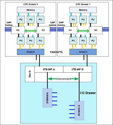
Figure 2-22 Redundant I/O interconnect for I/O drawer
Normally, the HCA2-C fanout in the first CPC drawer connects to the IFB-MP (A) card and services domain A in an I/O drawer. In the same fashion, the HCA2-C fanout of the second CPC drawer connects to the IFB-MP (B) card and services domain B in an I/O drawer. If the second CPC drawer is removed, or the connections from the second CPC drawer to the I/O drawer are removed, connectivity to domain B is maintained. The I/O is guided to domain B through the interconnect between IFB-MP (A) and IFB-MP (B).
PCIe I/O connection
The PCIe I/O drawer supports up to 32 PCIe features. They are organized in four hardware domains per drawer, as shown in Figure 2-23.

Figure 2-23 Redundant I/O interconnect for PCIe I/O drawer
Each domain is driven through a PCIe switch card. The two PCIe switch cards provide a backup path for each other through the passive connection in the PCIe I/O drawer backplane. During a PCIe fanout or cable failure, all 16 PCIe features in the two domains can be driven through a single PCIe switch card.
To support Redundant I/O Interconnect (RII) between front to back domain pairs 0,1 and 2,3, the two interconnects to each pair must be driven from two different PCIe fanouts. Normally, each PCIe interconnect in a pair supports the eight features in its domain. In backup operation mode, one PCIe interconnect supports all 16 features in the domain pair.
2.6.2 Enhanced drawer availability (EDA)
With EDA, the effect of CPC drawer replacement is minimized. In a multiple CPC drawer system, a single CPC drawer can be concurrently removed and reinstalled for an upgrade or repair. Removing a CPC drawer without affecting the workload requires sufficient resources in the remaining CPC drawer.
Before removing the CPC drawer, the contents of the PUs and memory of the drawer must be relocated. PUs must be available on the remaining CPC drawers to replace the deactivated drawer. Also, sufficient redundant memory must be available if no degradation of applications is allowed. To ensure that the CPC configuration supports removal of a CPC drawer with minimal effect on the workload, consider the flexible memory option. Any CPC drawer can be replaced, including the first CPC drawer that initially contains the HSA.
Removal of a CPC drawer also removes the CPC drawer connectivity to the I/O drawers, PCIe I/O drawers, and coupling links. The effect of the removal of the CPC drawer on the system is limited by the use of redundant I/O interconnect. For more information, see 2.6.1, “Redundant I/O interconnect” on page 60. However, all PSIFB links on the removed CPC drawer must be configured offline.
If the enhanced drawer availability and flexible memory options are not used when a CPC drawer needs to be replaced, the memory in the failing drawer is also removed. This might be necessary during an upgrade or a repair action. Until the removed CPC drawer is replaced, a power-on reset of the system with the remaining CPC drawer is supported.
2.6.3 CPC drawer upgrade
All fanouts that are used for I/O and coupling links are rebalanced concurrently as part of a CPC drawer addition.
2.7 Model configurations
When a z13 order is configured, PUs are characterized according to their intended usage. They can be ordered as any of the following items:
CP The processor is purchased and activated. CP supports the z/OS, z/VSE, z/VM, z/TPF, and Linux on z Systems operating systems. It can also run Coupling Facility Control Code and IBM zAware code.
Capacity marked CP A processor that is purchased for future use as a CP is marked as available capacity. It is offline and not available for use until an upgrade for the CP is installed. It does not affect software licenses or maintenance charges.
IFL The Integrated Facility for Linux is a processor that is purchased and activated for use by z/VM for Linux guests and Linux on z Systems operating systems. It can also run the IBM zAware code.
Unassigned IFL A processor that is purchased for future use as an IFL. It is offline and cannot be used until an upgrade for the IFL is installed. It does not affect software licenses or maintenance charges.
ICF An internal coupling facility (ICF) processor that is purchased and activated for use by the Coupling Facility Control Code.
zIIP An IBM z Integrated Information Processor (zIIP) that is purchased and activated to run eligible workloads, such as Java code under the control of a z/OS Java virtual machine (JVM) or z/OS XML System Services, DB2 Distributed Relational Database Architecture (DRDA), or z/OS Communication Server IPSec.
Additional SAP An optional processor that is purchased and activated for use as an SAP.
A minimum of one PU that is characterized as a CP, IFL, or ICF is required per system. The maximum number of CPs, IFLs, and ICFs is 141. The maximum number of zIIPs is always up to twice the number of PUs that are characterized as CPs.
Not all PUs on a model must be characterized.
Also, the following items are present in the z13, but they are not part of the PUs that clients purchase and require no characterization:
•System Assist Processor (SAP) to be used by the channel subsystem. The number of predefined SAPs depends on the z13 model.
•One integrated firmware processor (IFP). The IFP is used in the support of designated features, such as zEDC and 10GbE RoCE.
•Two spare PUs, which can transparently assume any characterization, if there is a permanent failure of another PU.
The z13 model nomenclature is based on the number of PUs that are available for client use in each configuration. The models are summarized in Table 2-9.
Table 2-9 zz13 configurations
|
Model
|
Drawers /
PUs
|
CPs
|
IFLs/uIFL
|
ICFs
|
zIIPs
|
Add. SAPs
|
Std. SAPs
|
Spares
|
IFP
|
|
N30
|
1/39
|
0 - 30
|
0 - 30
0 - 39 |
0 - 30
|
0 - 20
|
0 - 4
|
6
|
2
|
1
|
|
N63
|
2/78
|
0 - 63
|
0 - 63
0 - 62 |
0 - 63
|
0 - 42
|
0 - 8
|
12
|
2
|
1
|
|
N96
|
3/117
|
0 - 96
|
0 - 96
0 - 95 |
0 - 96
|
0 - 64
|
0 - 12
|
18
|
2
|
1
|
|
NC9
|
4/156
|
0 - 129
|
0 - 129
0 - 128 |
0 - 129
|
0 - 86
|
0 - 16
|
24
|
2
|
1
|
|
NE1
|
4/168
|
0 - 141
|
0 - 141
0 - 140 |
0 - 141
|
0 - 94
|
0 - 16
|
24
|
2
|
1
|
A capacity marker identifies the number of CPs that have been purchased. This number of purchased CPs is higher than or equal to the number of CPs that is actively used. The capacity marker marks the availability of purchased but unused capacity that is intended to be used as CPs in the future. They usually have this status for software-charging reasons. Unused CPs are not a factor when establishing the millions of service units (MSU) value that is used for charging monthly license charge (MLC) software, or when charged on a per-processor basis.
2.7.1 Upgrades
Concurrent upgrades of CPs, IFLs, ICFs, zIIPs, or SAPs are available for the z13. However, concurrent PU upgrades require that more PUs be installed but not activated.
Spare PUs are used to replace defective PUs. There are always two spare PUs on a z13. In the rare event of a PU failure, a spare PU is activated concurrently and transparently, and assigned the characteristics of the failing PU.
If an upgrade request cannot be accomplished within the configuration, a hardware upgrade is required. The upgrade enables the addition of one or more CPC drawers to accommodate the wanted capacity. Additional CPC drawers can be installed concurrently.
Although upgrades from one z13 model to another z13 model are concurrent, meaning that one or more CPC drawers can be added, there is one exception. Upgrades from any z13 (model N30, N63, N96, or NC9) to a model NE1 are disruptive, because the upgrade requires the replacement of all four CPC drawers.
Table 2-10 shows the possible upgrades within the z13 configuration range.
Table 2-10 z13 to z13 upgrade paths
|
To 2964
From 2964
|
Model N30
|
Model N63
|
Model N96
|
Model NC9
|
Model NE11
|
|
Model N30
|
-
|
Yes
|
Yes
|
Yes
|
Yes
|
|
Model N63
|
-
|
-
|
Yes
|
Yes
|
Yes
|
|
Model N96
|
-
|
-
|
-
|
Yes
|
Yes
|
|
Model NC9
|
-
|
-
|
-
|
-
|
Yes
|
1 Disruptive upgrade
You can also upgrade a z196 or a zEC12 to a z13 and preserve the CPC serial number (S/N). The I/O cards can also be carried forward (with certain restrictions) to the z13.
|
Important: Upgrades from z Enterprise EC12 (zEC12) and zEnterprise 196 (z196) are always disruptive.
|
Upgrade paths from any IBM zEnterprise 196 (EC) to any z13 are supported as listed in Table 2-11.
Table 2-11 z196 to z13 upgrade paths
|
To 2964
From 2817
|
Model N30
|
Model N63
|
Model N96
|
Model NC9
|
Model NE1
|
|
Model M15
|
Yes
|
Yes
|
Yes
|
Yes
|
Yes
|
|
Model M32
|
Yes
|
Yes
|
Yes
|
Yes
|
Yes
|
|
Model M49
|
Yes
|
Yes
|
Yes
|
Yes
|
Yes
|
|
Model M66
|
Yes
|
Yes
|
Yes
|
Yes
|
Yes
|
|
Model M80
|
Yes
|
Yes
|
Yes
|
Yes
|
Yes
|
Upgrades from any zEC12 to any z13 are supported as listed in Table 2-12.
Table 2-12 zEC12 to z13 upgrade paths
|
To 2964
From 2827
|
Model N30
|
Model N63
|
Model N96
|
Model NC9
|
Model NE1
|
|
Model H20
|
Yes
|
Yes
|
Yes
|
Yes
|
Yes
|
|
Model H43
|
Yes
|
Yes
|
Yes
|
Yes
|
Yes
|
|
Model H66
|
Yes
|
Yes
|
Yes
|
Yes
|
Yes
|
|
Model H89
|
Yes
|
Yes
|
Yes
|
Yes
|
Yes
|
|
Model HA1
|
Yes
|
Yes
|
Yes
|
Yes
|
Yes
|
2.7.2 Concurrent PU conversions
Assigned CPs, assigned IFLs, and unassigned IFLs, ICFs, zIIPs, and SAPs can be converted to other assigned or unassigned feature codes.
Most conversions are nondisruptive. In exceptional cases, the conversion can be disruptive, for example, when a model N30 with 30 CPs is converted to an all IFL system. In addition, an LPAR might be disrupted when PUs must be freed before they can be converted. Conversion information is summarized in Table 2-13.
Table 2-13 Concurrent PU conversions
|
To
From
|
CP
|
IFL
|
Unassigned IFL
|
ICF
|
zAAP
|
zIIP
|
SAP
|
|
CP
|
-
|
Yes
|
Yes
|
Yes
|
Yes
|
Yes
|
Yes
|
|
IFL
|
Yes
|
-
|
Yes
|
Yes
|
Yes
|
Yes
|
Yes
|
|
Unassigned IFL
|
Yes
|
Yes
|
-
|
Yes
|
Yes
|
Yes
|
Yes
|
|
ICF
|
Yes
|
Yes
|
Yes
|
-
|
Yes
|
Yes
|
Yes
|
|
zAAP
|
Yes
|
Yes
|
Yes
|
Yes
|
-
|
Yes
|
Yes
|
|
zIIP
|
Yes
|
Yes
|
Yes
|
Yes
|
Yes
|
-
|
Yes
|
|
SAP
|
Yes
|
Yes
|
Yes
|
Yes
|
Yes
|
Yes
|
-
|
2.7.3 Model capacity identifier
To recognize how many PUs are characterized as CPs, the store system information (STSI) instruction returns a model capacity identifier (MCI). The MCI determines the number and speed of characterized CPs. Characterization of a PU as an IFL, an ICF, or a zIIP is not reflected in the output of the STSI instruction because characterization has no effect on software charging. For more information about STSI output, see “Processor identification” on page 347.
Four distinct model capacity identifier ranges are recognized (one for full capacity and three for granular capacity):
•For full-capacity engines, model capacity identifiers 701 - 7E1 are used. They express the 141 possible capacity settings from 1 - 141 characterized CPs.
•Three model capacity identifier ranges offer a unique level of granular capacity at the low end. They are available when no more than 30 CPs are characterized. These three subcapacity settings are applied to up to 30 CPs, which offer 90 more capacity settings. For more information, see “Granular capacity” on page 66.
Granular capacity
The z13 offers 90 capacity settings at the low end of the processor. Only 30 CPs can have granular capacity. When subcapacity settings are used, other PUs beyond 30 can be characterized only as specialty engines.
The three defined ranges of subcapacity settings have model capacity identifiers numbered from 401- 430, 501 - 530, and 601 - 630.
|
Consideration: Within a z13, all CPs have the same capacity identifier. Specialty engines (IFLs, zIIPs, and ICFs) operate at full speed.
|
List of model capacity identifiers
Table 2-14 shows that regardless of the number of CPC drawers, a configuration with one characterized CP is possible. For example, model NE1 might have only one PU characterized as a CP.
Table 2-14 Model capacity identifiers
|
z13
|
Model capacity identifier
|
|
Model N30
|
701 - 730, 601 - 630, 501 - 530, and 401 - 430
|
|
Model N63
|
701 - 763, 601 - 630, 501 - 530, and 401 - 430
|
|
Model N96
|
701 - 796, 601 - 630, 501 - 530, and 401 - 430
|
|
Model NC9
|
701 - 7C9, 601 - 630, 501 - 530, and 401 - 430
|
|
Model NE1
|
701 - 7E1, 601 - 630, 501 - 530, and 401 - 430
|
|
Important: On z13, model capacity identifier 400 is used for IFL- or ICF-only configurations.
|
2.7.4 Model capacity identifier and MSU value
All model capacity identifiers have a related MSU value. The MSU values are used to determine the software license charge for MLC software. Tables with MSU values are available on the Mainframe Exhibits for IBM Servers website:
2.7.5 Capacity Backup (CBU)
CBU delivers temporary backup capacity in addition to the capacity that an installation might already have available in numbers of assigned CPs, IFLs, ICFs, zIIPs, and optional SAPs. CBU has the following types:
•CBU for CP
•CBU for IFL
•CBU for ICF
•CBU for zIIP
•Optional SAPs
When CBU for CP is added within the same capacity setting range (indicated by the model capacity indicator) as the currently assigned PUs, the total number of active PUs (the sum of all assigned CPs, IFLs, ICFs, zIIPs, and optional SAPs) plus the number of CBUs cannot exceed the total number of PUs available in the system.
When CBU for CP capacity is acquired by switching from one capacity setting to another, no more CBUs can be requested than the total number of PUs available for that capacity setting.
CBU and granular capacity
When CBU for CP is ordered, it replaces lost capacity for disaster recovery. Specialty engines (ICFs, IFLs, and zIIPs) always run at full capacity, and when running as a CBU to replace lost capacity for disaster recovery.
When you order CBU, specify the maximum number of CPs, ICFs, IFLs, zIIPs, and SAPs to be activated for disaster recovery. If disaster strikes, you decide how many of each of the contracted CBUs of any type to activate. The CBU rights are registered in one or more records in the CPC. Up to eight records can be active, which can contain various CBU activation variations that apply to the installation.
You can test the CBU. The number of CBU test activations that you can run for no additional fee in each CBU record is now determined by the number of years that are purchased with the CBU record. For example, a three-year CBU record has three test activations, as compared to a 1-year CBU record that has one test activation. You can increase the number of tests up to a maximum of 15 for each CBU record. The real activation of CBU lasts up to 90 days with a grace period of two days to prevent sudden deactivation when the 90-day period expires. The contract duration can be set from 1 - 5 years.
The CBU record describes the following properties that are related to the CBU:
•Number of CP CBUs allowed to be activated
•Number of IFL CBUs allowed to be activated
•Number of ICF CBUs allowed to be activated
•Number of zIIP CBUs allowed to be activated
•Number of SAP CBUs allowed to be activated
•Number of additional CBU tests that are allowed for this CBU record
•Number of total CBU years ordered (duration of the contract)
•Expiration date of the CBU contract
The record content of the CBU configuration is documented in IBM configurator output, which is shown in Example 2-1. In the example, one CBU record is made for a 5-year CBU contract without additional CBU tests for the activation of one CP CBU.
Example 2-1 Simple CBU record and related configuration features
On Demand Capacity Selections:
NEW00001 - CBU - CP(1) - Years(5) - Tests(5)
Resulting feature numbers in configuration:
6817 Total CBU Years Ordered 5
6818 CBU Records Ordered 1
6820 Single CBU CP-Year 5 
In Example 2-2, a second CBU record is added to the configuration for two CP CBUs, two IFL CBUs, and two zIIP CBUs, with five more tests and a 5-year CBU contract. The result is now a total number of 10 years of CBU ordered: Five years in the first record and five years in the second record. The two CBU records are independent, and can be activated individually. Five more CBU tests have been requested. Because a total of five years are contracted for a total of three CP CBUs (two IFL CBUs and two zIIP CBUs), they are shown as 15, 10, 10, and 10 CBU years for their respective types.
Example 2-2 Second CBU record and resulting configuration features
NEW00001 - CBU - Replenishment is required to reactivate
Expiration(06/21/2017)
NEW00002 - CBU - CP(2) - IFL(2) - zIIP(2)
Total Tests(10) - Years(5)
Resulting cumulative feature numbers in configuration:
6805 5 Additional CBU Tests 5
6817 Total CBU Years Ordered 10
6818 CBU Records Ordered 2
6820 Single CBU CP-Year 15
6822 Single CBU IFL-Year 10
6828 Single CBU zIIP-Year 10
CBU for CP rules
Consider the following guidelines when you are planning for CBU for CP capacity:
•The total CBU CP capacity features are equal to the number of added CPs plus the number of permanent CPs that change the capacity level. For example, if two CBU CPs are added to the current model 503, and the capacity level does not change, the 503 becomes 505:
(503 + 2 = 505)
If the capacity level changes from a 503 to a 606, the number of additional CPs (three) is added to the three CPs of the 503, resulting in a total number of CBU CP capacity features of six:
(3 + 3 = 6)
•The CBU cannot decrease the number of CPs.
•The CBU cannot lower the capacity setting.
|
Remember: Activation of CBU for CPs, IFLs, ICFs, zIIPs, and SAPs can be activated together with On/Off Capacity on Demand temporary upgrades. Both facilities can be on a single system, and can be activated simultaneously.
|
CBU for specialty engines
Specialty engines (ICFs, IFLs, and zIIPs) run at full capacity for all capacity settings. This also applies to CBU for specialty engines. Table 2-15 shows the minimum and maximum (min-max) numbers of all types of CBUs that might be activated on each of the models. The CBU record can contain larger numbers of CBUs than can fit in the current model.
Table 2-15 Capacity Backup matrix
|
Model
|
Total PUs available
|
CBU
CPs
min - max
|
CBU
IFLs
min - max
|
CBU
ICFs
min - max
|
CBU
zIIPs
min - max
|
CBU
SAPs
min - max
|
|
Model N30
|
30
|
0 - 30
|
0 - 30
|
0 - 30
|
0 - 20
|
0 - 4
|
|
Model N63
|
63
|
0 - 63
|
0 - 63
|
0 - 63
|
0 - 42
|
0 - 8
|
|
Model N96
|
96
|
0 - 96
|
0 - 96
|
0 - 96
|
0 - 64
|
0 - 12
|
|
Model NC9
|
129
|
0 - 129
|
0 - 129
|
0 - 129
|
0 - 86
|
0 - 16
|
|
Model NE1
|
141
|
0 - 141
|
0 - 141
|
0 - 1E1
|
0 - 94
|
0 - 16
|
Unassigned IFLs are ignored because they are considered spares, and are available for use as CBU. When an unassigned IFL is converted to an assigned IFL, or when more PUs are characterized as IFLs, the number of CBUs of any type that can be activated is decreased.
2.7.6 On/Off Capacity on Demand and CPs
On/Off Capacity on Demand (CoD) provides temporary capacity for all types of characterized PUs. Relative to granular capacity, On/Off CoD for CPs is treated similarly to the way CBU is handled.
On/Off CoD and granular capacity
When temporary capacity that is requested by On/Off CoD for CPs matches the model capacity identifier range of the permanent CP feature, the total number of active CPs equals the sum of the number of permanent CPs plus the number of temporary CPs ordered. For example, when a model capacity identifier 504 has two CP5s added temporarily, it becomes a model capacity identifier 506.
When the addition of temporary capacity that is requested by On/Off CoD for CPs results in a cross-over from one capacity identifier range to another, the total number of CPs active when the temporary CPs are activated is equal to the number of temporary CPs ordered. For example, when a CPC with model capacity identifier 504 specifies six CP6 temporary CPs through On/Off CoD, the result is a CPC with model capacity identifier 606. A cross-over does not necessarily mean that the CP count for the additional temporary capacity increases+. The same 504 might temporarily be upgraded to a CPC with model capacity identifier 704. In this case, the number of CPs does not increase, but more temporary capacity is achieved.
On/Off CoD guidelines
When you request temporary capacity, consider the following guidelines:
•Temporary capacity must be greater than permanent capacity.
•Temporary capacity cannot be more than double the purchased capacity.
•On/Off CoD cannot decrease the number of engines on the CPC.
•Adding more engines than are currently installed is not possible.
For more information about temporary capacity increases, see Chapter 8, “System upgrades” on page 307.
2.8 Power and cooling
The z13 power and cooling system is a continuation of zEC12 with the addition of improvements regarding availability, temperature tolerance, and vectored (directional) air output. The air-cooled z13 now has a RU N+2 design for the pumps and blowers. With the new rear cover design for vectored air output, you can choose whether the output air goes up or down. The water-cooled system is still an option for the z13. The Top Exit Power feature is available for the z13. Combined with the Top Exit I/O Cabling feature, it gives you more options when you are planning your computer room cabling. For more information about the z13 Top Exit features, see 10.3, “z13 physical planning” on page 392.
2.8.1 Power consumption
The system operates with two fully redundant power supplies. One is in the front side of the Z frame, and the other is in the rear side of the Z frame. Each power supply has either one or two power cords. The number of power cords that are required depends on the system configuration. The total loss of one power supply has no impact on system operation.
Systems that specify two power cords can be brought up with one power cord and continue to run.
The larger systems that have a minimum of four Bulk Power Regulator (BPR) pairs that are installed must have four power cords installed. Systems that specify four power cords can be started with two power cords on the same side with sufficient power to keep the system running.
Power cords attach to either a three-phase, 50/60 Hz, 200 - 480 V AC power source, or a 380 - 520 V DC power source.
A Balanced Power Plan Ahead feature is available for future growth, helping to ensure adequate and balanced power for all possible configurations. With this feature, system downtime for upgrading a server is eliminated by including the maximum power requirements in terms of BPRs and power cords to your installation.
For ancillary equipment, such as the Hardware Management Console, its display, and its switch, additional single phase outlets are required.
The power requirements depend on the cooling facility that is installed, and on the number of CPC drawers and I/O units that are installed. For more information about the requirements that are related to the number of installed I/O units, see 10.1.2, “Power requirements and consumption” on page 384.
2.8.2 High Voltage Direct Current power feature
The High Voltage Direct Current power feature is an option for IBM z13. It allows z13 to directly use the high voltage DC distribution that is shown in Figure 2-24 on page 72. A direct HV DC data center power design can improve data center energy efficiency by removing the need for a DC to AC inversion step.
The z13 bulk power supplies have been modified to support HV DC, so the only difference in the shipped hardware to implement this option is the DC power cords. Because HV DC is a new technology, there are multiple proposed standards. The z13 supports both ground referenced and dual polarity HV DC supplies, such as +/-190 V, +/-260 V, and +380 V. Beyond the data center uninterruptible power supply and power distribution energy savings, a z13 that runs on HV DC power draws 1 - 3% less input power. HV DC does not change the number of power cords that a system requires.

Figure 2-24 AC versus DC distribution
2.8.3 Internal Battery Feature (IBF)
The Internal Battery Feature (IBF) is an optional feature on the z13 server. It is shown in Figure 2-1 on page 30 for air-cooled (radiator) models and in Figure 2-2 on page 31 for water-cooled models. The IBF provides a local uninterrupted power source.
The IBF further enhances the robustness of the power design, increasing power line disturbance immunity. It provides battery power to preserve processor data if there is a loss of power on all power feeds from the computer room. The IBF can hold power briefly during a brownout, or for orderly shutdown if there is a longer outage. For information about the hold times, which depend on the I/O configuration and amount of CPC drawers, see 10.1.4, “Internal Battery Feature (IBF)” on page 390.
2.8.4 Power capping and saving
Power capping limits the maximum power consumption and reduces the cooling requirements for the zBX. A z13 does not support power capping.
The z13 server has a mechanism to vary the frequency and voltage that it supplies its chips. The mechanism can be used to reduce the energy consumption of the system in periods of low usage or for systems that are designed mainly for disaster recovery. The mechanism is under the full control of the client. The client controls are implemented in the HMC, SE, and Active Energy Manager where you can choose between High Performance (default) or Low Power (power saving).The expectation is that the frequency change is 20%, the voltage change is 9%, and the total power savings is 6% - 16%, depending on the configuration.
2.8.5 Power estimation tool
The power estimation tool for the z13 allows you to enter your precise server configuration to obtain an estimate of power consumption. Log in to the Resource link with your user ID. Click Planning → Tools → Power Estimation Tools. Specify the quantity for the features that are installed in your system. This tool estimates the power consumption for the specified configuration. The tool does not verify that the specified configuration can be physically built.
|
Tip: The exact power consumption for your system varies. The object of the tool is to estimate the power requirements to aid you in planning for your system installation. Actual power consumption after installation can be confirmed by using the HMC Monitors Dashboard task.
|
To learn how to check the current values of your z13, see 10.4.1, “Power usage” on page 398.
2.8.6 Cooling
The PU single chip modules (SCMs) are cooled by a cold plate that is connected to the internal water-cooling loop. The SC SCMs are air-cooled. In an air-cooled system, the RUs dissipate the heat from the internal water loop with air. The radiator units provide improved availability with N+2 pumps and blowers. The WCUs are fully redundant in an N+1 arrangement.
Air-cooled models
In the z13, CPC drawer, SC SCM, PCIe I/O drawers, I/O drawers, and power enclosures are all cooled by forced air with blowers that are controlled by the Move Device Assembly (MDA).
The PU SCMs in the CPC drawers are cooled by water. The internal closed water loop takes heat away from PU SCMs by circulating water between the radiator heat exchanger and the cold plate that is mounted on the PU SCMs. For more information, see 2.8.7, “Radiator Unit” on page 74.
Although the PU SCMs are cooled by water, the heat is exhausted into the room from the radiator heat exchanger by forced air with blowers. At the system level, z13 is still an air-cooled system.
Water-cooled models
The z13 is available as a water-cooled system. With water-cooling unit (WCU) technology, the z13 can transfer most of the heat it generates into the building’s chilled water and effectively reduce the heat output to the computer room.
Unlike the radiator in air-cooled models, a WCU has two water loops: an internal closed water loop and an external (chilled) water loop. The external water loop connects to the client-supplied building’s chilled water. The internal water loop circulates between the WCU heat exchanger and the PU SCMs cold plates. The loop takes heat away from the PU SCMs and transfers it to the external water loop in the WCU’s heat exchanger. For more information, see 2.8.8, “Water-cooling unit” on page 76.
In addition to the PU SCMs, the internal water loop also circulates through two heat exchangers that are in the path of the exhaust air in the rear of the frames. These heat exchangers remove approximately 60% - 65% of the residual heat from the I/O drawers, PCIe I/O drawers, the air-cooled logic in the CPC drawers, and the power enclosures. Almost two-thirds of the total heat that is generated can be removed from the room by the chilled water.
The selection of air-cooled models or water-cooled models is done when ordering, and the appropriate equipment is factory-installed. An MES (conversion) from an air-cooled model to a water-cooled model and vice versa is not allowed.
2.8.7 Radiator Unit
The Radiator Unit provides cooling to PU SCMs with closed loop water. No connection to an external chilled water supply is required. For the z13, the internal circulating water is conditioned water that is added to the radiator unit during system installation with the Fill and Drain Tool (FC 3380). The Fill and Drain Tool (FDT) is included with the new z13, but if there is already an FDT from a zEC12 (FC 3378) in the data center, you can order an upgrade kit (FC 3379) to have the same equipment as in the FC 3380, and it can be used for the zEC12 and z13. The FDT is used to provide the internal water at the installation, for maintenance, and at discontinuance.
Figure 2-25 shows the FDT.

Figure 2-25 Fill and Drain Tool (FDT)
The radiator unit connects to all four CPC drawers (if installed) and cools all PU SCMs simultaneously. The cooling capability is a redundant N+2 design, so a single working pump and blower can support the entire load. The replacement of one pump or blower can be done concurrently and has no performance impact.
As Figure 2-26 shows, the water pumps, manifold assembly, radiator assembly (which includes the heat exchanger), and blowers are the main components of the z13 RU.
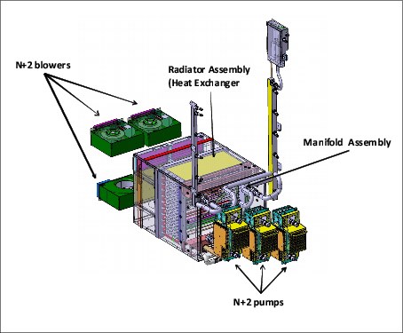
Figure 2-26 Radiator unit
Figure 2-27 shows the closed water loop in the radiator unit. The warm water exiting from the PU SCMs cold plates enters pumps through a common manifold, and is pumped through a heat exchanger where heat is extracted by the air flowing across the heat exchanger fins. The cooled water is then recirculated back into the PU SCMs cold plates.
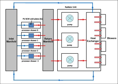
Figure 2-27 Radiator cooling system
2.8.8 Water-cooling unit
The z13 continues to provide the ability to cool systems with building-provide chilled water by employing the WCU technology. The PU SCMs in the CPC drawers are cooled by internal closed loop water. The internal closed loop water exchanges heat with building-provided chilled water in the WCU heat exchanger. The source of the building’s chilled water is provided by the client.
Figure 2-28 shows a WCU.

Figure 2-28 Water-cooling unit
The water in the closed loop within the system exchanges heat with the continuous supply of building-provided chilled water. This water circulates between the PU SCMs cold plates and a heat exchanger within the WCU. Heat from the PU SCMs is transferred to the cold plates, where it is in turn transferred to the circulating system water (closed loop). The system water then loses its heat to the building-provided chilled water within the WCU’s heat exchanger. The PU SCMs are cooled efficiently in this manner.
A simplified high-level diagram that illustrates this principle is shown in Figure 2-29.
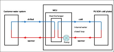
Figure 2-29 WCU water loop
The z13 operates with two fully redundant WCUs. These water-cooling units have each their own facility feed and return water connections. If water is interrupted to one of the units, the other unit picks up the entire load, and the server continues to operate without interruption. You must provide independent redundant water loops to the water-cooling units to obtain full redundancy.
The internal circulating water is conditioned water that is added to the radiator unit during system installation with the Fill and Drain Tool (FC 3380). The FDT is included with the new z13, but if there is already an FDT from a zEC12 (FC 3378) in the data center, you can order an upgrade kit (FC 3379) to have the same equipment as in the FC 3380, and it can be used for the zEC12 and z13. The FDT is used to provide the internal water at the installation, for maintenance and, discontinuance. Figure 2-25 on page 74 shows the FDT.
Exhaust Air Heat Exchanger
In the z13, all water-cooled models have two Exhaust Air Heat Exchanger units that are installed on the rear of the A and Z frames, as shown in Figure 2-30. These units remove heat from the internal system water loop, and internal air exits the server into the hot air exhaust aisle.

Figure 2-30 Water-cooled model - rear view
In addition to the PU SCMs cold plates, the internal water loop also circulates through these two heat exchangers. These exchangers are in the path of the exhaust air in the rear of the frames. These heat exchangers remove approximately 65% of the residual heat from the I/O drawers, PCIe I/O drawer, the air-cooled logic in the CPC drawer, and the power enclosures. The goal is for two-thirds of the total heat that is generated to be removed from the room by the chilled water.
If one client water supply or one WCU fails, the remaining feed maintains PU SMCs cooling. The WCUs and the associated drive card are concurrently replaceable. Also, the heat exchangers can be disconnected and removed from the system concurrently.
Considerations before you order
The water-cooling option is preferable because it can substantially lower the total power consumption of the z13 and the total cost of ownership for the CPC. This savings is greater for the larger models of the z13, as shown in Table 2-16.
The water-cooling option cannot be installed in the field. Therefore, you must carefully consider the present and future computer room and CPC configuration options before you decide what cooling option to order. For more information, see 10.1.3, “Cooling requirements” on page 387.
Table 2-16 Heat to water based on temperature
|
Temperature
|
Three CPC drawer typical configuration
|
Four CPC drawer typical configuration
|
Four CPC drawer maximum power configuration
|
|
Water-cooled system power in normal room/hot room
|
|||
|
|
12.9 kW/14.1 kW
|
17.4 kW/19.0 kW
|
24.7 kW/26.3 kW
|
|
Inlet air temperature
|
Heat to water and as % of total system heat load
|
||
|
18°C (64°F)
|
7.3 kW (57%)
|
9.8 kW (56%)
|
12.6 kW (51%)
|
|
23°C (73°F)
|
9.5 kW (74%)
|
12.6 kW (72%)
|
15.6 kW (63%)
|
|
27°C (80.6°F)
|
11.5 kW (89%)
|
14.8 kW (85%)
|
18.0 kW (73%)
|
|
32°C (89.6°F)
(hot room) |
14.8 kW (105%)
|
18.2 kW (96%)
|
21.6 kW (82%)
|
2.9 Summary of z13 structure
Table 2-17 summarizes all aspects of the z13 structure.
Table 2-17 System structure summary
|
Description
|
Model N30
|
Model N63
|
Model N96
|
Model NC9
|
Model NE1
|
|
Number of CPC drawers
|
1
|
2
|
3
|
4
|
4
|
|
Number of SCMs
|
8
|
16
|
24
|
32
|
32
|
|
Total number of PUs
|
39
|
78
|
117
|
156
|
168
|
|
Maximum number of characterized PUs
|
30
|
63
|
96
|
129
|
141
|
|
Number of CPs
|
0 - 30
|
0 - 63
|
0 - 96
|
0 - 129
|
0 - 141
|
|
Number of IFLs
|
0 - 30
|
0 - 63
|
0 - 96
|
0 - 129
|
0 - 141
|
|
Number of ICFs
|
0 - 30
|
0 - 63
|
0 - 96
|
0 - 129
|
0 - 141
|
|
Number of zIIPs
|
0 - 20
|
0 - 42
|
0 - 64
|
0 - 86
|
0 - 94
|
|
Standard SAPs
|
6
|
12
|
18
|
24
|
24
|
|
Additional SAPs
|
0 - 4
|
0 - 8
|
0 - 12
|
0 - 16
|
0 - 16
|
|
Number of IFP
|
1
|
1
|
1
|
1
|
1
|
|
Standard spare PUs
|
2
|
2
|
2
|
2
|
2
|
|
Enabled memory sizes
|
64 - 2464 GB
|
64 - 5024 GB
|
64 - 7584 GB
|
64 - 10144 GB
|
64 - 10144 GB
|
|
Flexible memory sizes
|
N/A
|
64 - 2464 GB
|
64 - 5024 GB
|
64 - 7584 GB
|
64 - 7584 GB
|
|
L1 cache per PU
|
96/128 KB(I/D)
|
96/128 KB(I/D)
|
96/128 KB(I/D)
|
96/128 KB(I/D)
|
96/128 KB(I/D)
|
|
L2 cache per PU
|
2/2 MB (I/D)
|
2/2 MB (I/D)
|
2/2 MB (I/D)
|
2/2 MB (I/D)
|
2/2 MB (I/D)
|
|
L3 shared cache per PU chip
|
64 MB
|
64 MB
|
64 MB
|
64 MB
|
64 MB
|
|
L4 shared cache per node
|
480 MB
|
480 MB
|
480 MB
|
480 MB
|
480 MB
|
|
L4 NIC directory per node
|
224 MB
|
224 MB
|
224 MB
|
224 MB
|
224 MB
|
|
Cycle time (ns)
|
0.2
|
0.2
|
0.2
|
0.2
|
0.2
|
|
Clock frequency
|
5.0 GHz
|
5.0 GHz
|
5.0 GHz
|
5.0 GHz
|
5.0 GHz
|
|
Maximum number of PCIe fanouts
|
10
|
20
|
30
|
40
|
40
|
|
Maximum number of IFB fanouts
|
4
|
8
|
12
|
16
|
16
|
|
I/O interface per IFB cable
|
6 GBps
|
6 GBps
|
6 GBps
|
6 GBps
|
6 GBps
|
|
I/O interface per PCIe cable
|
16 GBps
|
16 GBps
|
16 GBps
|
16 GBps
|
16 GBps
|
|
Number of support elements
|
2
|
2
|
2
|
2
|
2
|
|
External AC power
|
3 phase
|
3 phase
|
3 phase
|
3 phase
|
a3 phase
|
|
Optional external DC
|
520 V/380 V
|
520 V/380 V
|
520 V/380 V
|
520 V/380 V
|
520 V/380 V
|
|
Internal Battery Feature
|
Optional
|
Optional
|
Optional
|
Optional
|
Optional
|
1 The air density sensor measures air pressure and it is used to control blower speed.
..................Content has been hidden....................
You can't read the all page of ebook, please click here login for view all page.