
Chapter 3
Advanced Computer Hardware
Objectives
Upon completion of this chapter, you will be able to answer the following questions:
What are general and fire safety standards?
What are safe working conditions and procedures?
What procedures help protect equipment and data?
What procedures help to properly dispose of hazardous computer components and related material?
What tools and software are used with personal computer components, and what is their purpose?
What is the proper way to use tools?
What should I expect the first time I boot the computer?
What is the BIOS setup program?
How do I use beep codes?
Key Terms
This chapter uses the following key terms. You can find the definitions in the glossary at the end of the book.
audio editing workstation page 147
basic input/output system (BIOS) page 99
CAD or CAM (CAx) workstation page 145
complementary metal-oxide semiconductor (CMOS) page 99
Complex Instruction Set Computer (CISC) page 112
execute disable bit (NX) page 114
graphics card cooling system page 115
Integrated Drive Electronics (IDE) page 134
integrated graphics processing unit (GPU) page 114
master boot record (MBR) page 98
network-attached storage (NAS) page 154
power-on self-test (POST) page 99
Reduced Instruction Set Computer (RISC) page 112
Redundant Array of Independent Disks (RAID) page 117
safety data sheet (SDS) page 157
shielded twisted pair (STP) page 131
Small Computer System Interface (SCSI) page 133
standby power supply (SPS) page 111
Trusted Platform Module (TPM) page 105
Unified Extensible Firmware Interface (UEFI) page 99
uninterruptible power supply (UPS) page 110
unshielded twisted pair (UTP) page 131
Virtual Desktop Infrastructure (VDI) page 150
Introduction to Advanced Computer Hardware (3.0)
A technician’s knowledge must extend beyond knowing how to assemble a computer. You need to have in-depth knowledge of computer system architecture and how each component operates and interacts with other components. This depth of knowledge is necessary when you have to upgrade a computer with new components that must be compatible with existing components and also when you build computers for very specialized applications. This chapter covers the computer boot process, protecting the computer from power fluctuations, multicore processors, redundancy through multiple storage drives, and protecting the environment from hazardous materials found inside computer components.
You will learn about the computer boot process, including the power-on self-test (POST) conducted by the BIOS. You will explore various BIOS and UEFI settings and how they impact this process. You will explore basic electrical theory and Ohm’s law and calculate voltage, current, resistance, and power. Power fluctuations can damage computer components, and you will learn how to mitigate the risk of power fluctuations with surge protectors, uninterruptible power supplies (UPSs), and standby power supplies (SPSs). You will learn how to provide storage redundancy and load balancing using redundant arrays of independent disks (RAID). You will also learn how to upgrade computer components and configure specialized computers. Finally, after upgrading a computer, technicians must dispose of the old parts properly. Many computer components contain hazardous materials, such as mercury and rare earth metals in batteries and deadly voltage levels in power supplies. You will learn the risks posed by these components and how to dispose of them properly.
This chapter includes a lab in which you will research hardware upgrades to a computer system. You will use several sources to gather information about the computer hardware components and make recommendations for upgraded components. You will also discuss your recommended upgrade choices.
Boot the Computer (3.1)
Booting a computer refers to turning it on and beginning the startup sequence, verifying hardware, and loading operating system software. ROM BIOS is an integral part of the boot process. Once power is supplied to the computer, diagnostics are run, and BIOS takes control of the boot and searches for the master boot loader (MBL). The master boot loader reads the master boot record (MBR) and runs the code. At this point, the BIOS stops controlling the system, and control is then passed to the boot loader program. The boot loader program is configured to locate and load an operating system from the boot device.
POST, BIOS, CMOS, and UEFI (3.1.1)
A power-on self-test (POST) is a self-diagnostic testing system in which the computer produces codes to signal problems to help identify hardware issues with the computer. The codes generated indicate the causes of different problems. The POST program is stored in the BIOS memory.
The basic input/output system (BIOS) is firmware that is built into the motherboard that initializes the computer’s hardware as the computer is being booted. The BIOS can’t be rewritten; it is read-only memory (ROM). BIOS and CMOS work together, but they do different things.
Complementary metal-oxide semiconductor (CMOS) is RAM that is volatile memory. In order for the CMOS to maintain its settings when no power is applied to the system or when it is in standby, there is a CMOS battery on the motherboard. The CMOS battery provides low voltage to the system so the CMOS keeps its settings. A CMOS editor program is used because BIOS ROM cannot be rewritten to access and make changes to programs stored in the BIOS. The custom settings configured in the BIOS—such as date and time, the boot sequence, or hardware settings—are made and stored in CMOS.
Unified Extensible Firmware Interface (UEFI) is a new type of BIOS that has many advantages, including a GUI that is user friendly compared to older BIOS versions, the ability to recognize larger hard drives, and a built-in feature called secure boot. Secure boot stops any digitally unsigned drivers from loading and also helps stop malicious software.
Video Demonstration 3.1.1.1: BIOS - UEFI Menus

Refer to the online course to view this video.
POST (3.1.1.2)
When a computer is booted, the basic input/output system (BIOS) performs a hardware check on the main components of the computer. This check is called a power-on self-test (POST).
For instance, Figure 3-1 displays a screen capture of a sample POST being performed. Notice that the computer checks whether the computer hardware is operating correctly.

Figure 3-1 POST
If a device is malfunctioning, an error code or beep code alerts the technician of the problem. If there is a hardware problem, a blank screen might appear at bootup, and the computer may emit a series of beeps.
BIOS manufacturers use different codes to indicate hardware problems. Table 3-1 shows a chart of common beep codes. However, motherboard manufacturers may use different beep codes. Always consult the motherboard documentation to get the beep codes for your computer.
Table 3-1 Common Beep Codes
Beep Code |
Meaning |
Cause |
1 beep (no video) |
Memory refresh failure |
Bad memory |
2 beeps |
Memory parity error |
Bad memory |
3 beeps |
Base 64 mem failure |
Bad memory |
4 beeps |
Timer not operational |
Bad motherboard |
5 beeps |
Processor error |
Bad processor |
6 beeps |
8042 Gate A2.0 failure |
Bad CPU or motherboard |
7 beeps |
Processor exception |
Bad processor |
8. beeps |
Video memory error |
Bad video card or memory |
9 beeps |
ROM checksum error |
Bad BIOS |
10 beeps |
CMOS checksum error |
Bad motherboard |
11 beeps |
Cache memory bad |
Bad CPU or motherboard |
Installation Tip
To determine whether POST is working properly, remove all the RAM modules from the computer and power it on. The computer should emit the beep code for a computer with no RAM installed. Doing this will not harm the computer.
BIOS and CMOS (3.1.1.3)
All motherboards need BIOS to operate. BIOS is a ROM chip on the motherboard that contains a small program. This program controls the communication between the operating system and the hardware.
Along with the POST, BIOS also identifies the following:
Which drives are available
Which drives are bootable
How the memory is configured and when it can be used
How PCIe and PCI expansion slots are configured
How SATA and USB ports are configured
Motherboard power management features
The motherboard manufacturer saves the motherboard BIOS settings in a CMOS memory chip such as the one shown in Figure 3-2.

Figure 3-2 CMOS Chip
When a computer boots, the BIOS software reads the configured settings stored in CMOS to determine how to configure the hardware.
The BIOS settings are retained by CMOS using a battery, such as the one shown in Figure 3-3. However, if the battery fails, important settings can be lost. Therefore, it is recommended that BIOS settings be documented.
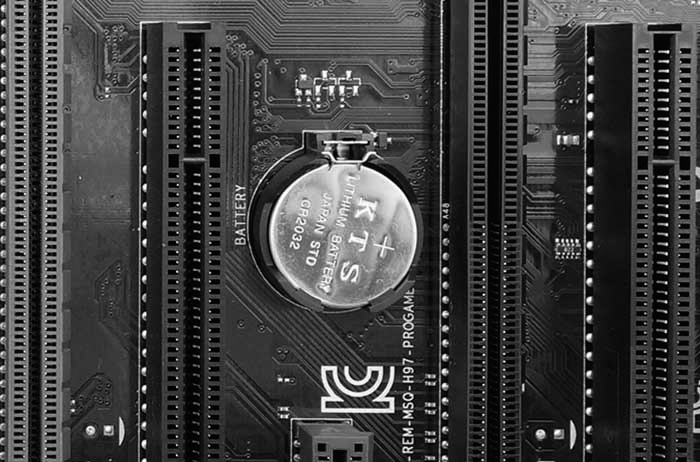
Figure 3-3 CMOS Battery
Note
An easy way to document these settings is to take pictures of the various BIOS settings available to record them for later use.
Installation Tip
If the computer’s time and date are incorrect, the CMOS battery might be dead or getting very low.
UEFI (3.1.1.4)
Most computers today run UEFI. Figure 3-4 shows an example.

Figure 3-4 UEFI BIOS Utility Program
All new computers come with UEFI, which provides additional features and addresses security issues with legacy BIOS. You might see “BIOS/UEFI” when booting into your BIOS settings. This is because Intel chips currently support backward compatibility with legacy BIOS systems. However, by 2020, Intel will end support for legacy BIOS. For more information, do an Internet search for “Intel to remove legacy BIOS.”
Note
This section uses the terms BIOS, UEFI, and BIOS/UEFI interchangeably. In addition, manufacturers may continue to label their UEFI programs with “BIOS” so that users know the programs support the same functions.
UEFI includes the same settings as traditional BIOS but also provides additional options. For example, UEFI can provide a mouse-enabled software interface instead of the traditional BIOS screens. However, most systems have a text-based interface, similar to legacy BIOS systems.
UEFI can run on 32-bit and 64-bit systems, supports larger boot drives, and includes additional features, such as secure boot. Secure boot ensures that your computer boots to your specified operating system. This helps prevent rootkits from taking over the system. For more information, do an Internet search for “Secure boot and rootkits.”
Note
The UEFI setup screens in this section are for reference only and most likely will not look the same as yours. Please consider them as a guide and refer to your motherboard manufacturer’s documents.
Check Your Understanding 3.1.1.5: BIOS and UEFI Terminology

Refer to the online course to complete this activity.
Lab 3.1.1.6: Investigate BIOS or UEFI Settings
![]()
In this lab, you will boot the computer, explore the firmware setup utility program, and change the boot order sequence.
BIOS/UEFI Configuration (3.1.2)
Both UEFI and BIOS are low-level software that starts when you boot your PC before booting your operating system, but UEFI has a more modern approach to accessing settings, using a mouse and graphics. It also supports larger hard drives, faster boot times, more security features, and other options.
Video Demonstration 3.1.2.1: Configure BIOS - UEFI Settings
Refer to the online course to view this video.
BIOS and UEFI Security (3.1.2.2)
The legacy BIOS supports some security features to protect the BIOS setting. UEFI adds additional security features. These are some common security features found in the BIOS/UEFI systems:
Passwords: Passwords allow for different levels of access to the BIOS settings. Usually, there are two password settings that can be altered: the supervisor password and the user password. The supervisor password can access all user-access passwords and all BIOS screens and settings. The user password gives access to the BIOS based on a defined level. Table 3-2 lists common levels of user access to BIOS. The supervisor password must be set before the user password can be configured.
Table 3-2 Access Levels
Access Level |
Level Description |
All screens and settings are available, except the supervisor password setting. |
|
Limited access |
Changes can be made to certain settings only, such as the time and date. |
All screens are available, but no settings can be changed. |
|
No access |
No access is provided to the BIOS setup utility. |
Drive encryption: A hard drive can be encrypted to prevent data theft. Encryption changes the data on the drive into code. Without the correct password, the computer cannot boot, and data read from the hard drive cannot be understood. Even if the hard drive is placed in another computer, the data remains encrypted.
LoJack: This is a security feature that consists of two programs: the persistence module and the application agent. The persistence module is embedded in the BIOS, and the application agent is installed by the user. When installed, the persistence module in the BIOS is activated and cannot be turned off. The application agent routinely contacts a monitoring center over the Internet to report device information and location. The owner can perform the following functions:
Locate the device using Wi-Fi or IP geolocation to see the last location.
Lock the device remotely to prevent access to personal information. Display a customized message on the screen.
Delete all files on the device to protect personal information and prevent identity theft.
Trusted Platform Module (TPM): This is a chip designed to secure hardware by storing encryption keys, digital certificates, passwords, and data. TPM is used by Windows to support BitLocker full-disk encryption.
Secure boot: Secure boot is a UEFI security standard which ensures that a computer only boots an OS that is trusted by the motherboard manufacturer. Secure boot prevents an “unauthorized” OS from loading during startup.
Update the Firmware (3.1.2.3)
Motherboard manufacturers may publish updated BIOS versions to provide enhancements to system stability, compatibility, and performance. However, updating the firmware is risky. The release notes, such as those shown in Figure 3-5, describe the upgrade to the product, compatibility improvements, and the known bugs that have been addressed. Some newer devices operate properly only with an updated BIOS version installed. You can usually find the current version on the main screen of the BIOS/UEFI interface.

Figure 3-5 BIOS Release Notes
Before updating motherboard firmware, record the manufacturer of the BIOS and the motherboard model. Use this information to identify the exact files to download from the motherboard manufacturer’s site. Update the firmware only if there are problems with the system hardware or to add functionality to the system.
Early computer BIOS information was contained in ROM chips. To upgrade the BIOS information, the ROM chip had to be physically replaced, which was not always possible. Modern BIOS chips are electrically erasable programmable read-only memory (EEPROM), which the user can upgrade without opening the computer case. This process is called flashing the BIOS.
To download a new BIOS, consult the manufacturer’s website and follow the recommended installation procedures. Installing BIOS software online may involve downloading a new BIOS file, copying or extracting files to removable media, and then booting from the removable media. An installation program prompts the user for information to complete the process.
Many motherboard manufacturers now provide software to flash the BIOS from within an operating system. For example, the ASUS EZ Update utility automatically updates a motherboard’s software, drivers, and the BIOS version. It also enables a user to manually update a saved BIOS and select a boot logo when the system goes into POST. The utility is included with the motherboard, or it can be downloaded from the ASUS website.
Caution
An improperly installed or aborted BIOS update can cause the computer to become unusable.
Check Your Understanding 3.1.2.4: BIOS and UEFI Configuration Terminology
Refer to the online course to complete this activity.
Lab 3.1.2.5: Search for BIOS or UEFI Firmware Updates
![]()
In this lab, you will identify the current BIOS or UEFI version and then search for BIOS or UEFI update files.
Lab 3.1.2.6: Install Windows
![]()
In this lab, you will perform a basic installation of Windows.
Lab 3.1.2.7: Install Third-Party Software in Windows
![]()
In this lab, you will install third-party software.
Electrical Power (3.2)
Electrical power is the rate at which electrical energy is being transferred.
Wattage and Voltage (3.2.1)
Electrical power is the product of voltage, which is electrical pressure, and current, which is the flow of electricity, measured in wattage.
Wattage and Voltage (3.2.1.1)
Power supply specifications are typically expressed in watts (W). To understand what a watt is, refer to the interactive image in the online course, which describes the four basic units of electricity that a computer technician must know.
The basic equation known as Ohm’s law indicates that voltage is equal to the current multiplied by the resistance: V = IR. In an electrical system, power is equal to the voltage multiplied by the current: P = VI. The following are definitions of power-related terminology:
Voltage, measured in volts (V)
This is a measure of work required to move a charge from one location to another.
A computer power supply usually produces several different voltages.
Resistance, measured in Ohms (O)
This refers to the opposition to the flow of current in a circuit.
Lower resistance allows more current to flow through a circuit.
A good fuse has low resistance, or almost 0 ohms.
Current, measured in amperes, or amps (A)
This is a measure of the number of electrons moving through a circuit per second.
Computer power supplies deliver different amperages for each output voltage.
Power, measured in watts (W)
This is a measure of the work required to move electrons through a circuit (voltage), multiplied by the number of electrons going through that circuit per second (current).
Computer power supplies are rated in watts.
Power Supply Voltage Setting (3.2.1.2)
On the back of some power supplies is a small switch called the voltage selector switch, as shown in Figure 3-6.
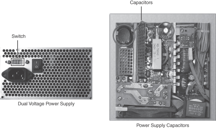
Figure 3-6 Power Supply Voltage Setting and Capacitors
This switch sets the input voltage to the power supply to either 110V/115V or 220V/230V. A power supply with this switch is called a dual voltage power supply. The correct voltage setting depends on the country where the power supply is used. Setting the voltage switch to the incorrect input voltage could damage the power supply and other parts of the computer. If a power supply does not have this switch, it automatically detects and sets the correct voltage.
Caution
Do not open a power supply. Electronic capacitors located inside a power supply can hold a charge for extended periods of time.
For more information about power supplies, refer to https://www.newegg.com/insider/how-to-choose-a-pc-power-supply-buying-guide/.
Lab 3.2.1.3: Ohm’s Law
![]()
In this lab, you will answer questions based on electricity and Ohm’s law.
Power Fluctuation and Protection (3.2.2)
Power fluctuations occur commonly almost everywhere. Happenings such as lightning, power line outages, accidental power interruptions, and simple line voltage variance can affect your computer. As important as electronic device usage has become in business and personal life, it is important to take steps to ensure the safety of all devices so that no damage is done to them in the event of a power fluctuation.
Power Fluctuation Types (3.2.2.1)
Voltage is a measure of energy required to move a charge from one location to another. The movement of electrons is called current. Computer circuits need voltage and current to operate electronic components. When the voltage in a computer is not accurate or steady, computer components might not operate correctly. Unsteady voltages are called power fluctuations.
The following types of AC power fluctuations can cause data loss or hardware failure:
Blackout: Complete loss of AC power. A blown fuse, damaged transformer, or downed power line can cause a blackout.
Brownout: A reduced voltage level of AC power that lasts for a period of time. Brownouts occur when the power line voltage drops below 80% of the normal voltage level and when electrical circuits are overloaded.
Noise: Interference from generators and lightning. Noise results in poor-quality power, which can cause errors in a computer system.
Spike: A sudden increase in voltage that lasts for a short period and exceeds 100% of the normal voltage on a line. Spikes can be caused by lightning strikes but can also occur when the electrical system comes back on after a blackout.
Power surge: A dramatic increase in voltage above the normal flow of electrical current. A power surge lasts for a few nanoseconds, or one-billionth of a second.
Power Protection Devices (3.2.2.2)
To help shield against power fluctuation problems, use devices to protect the data and computer equipment:
Surge protector: Helps protect against damage from surges and spikes. A surge suppressor diverts extra electrical voltage that is on the line to the ground. The amount of protection offered by a surge protector is measured in joules. The higher the joule rating, the more energy the surge protector can absorb over time. Once the number of joules is reached, the surge protector no longer provides protection and needs to be replaced.
Uninterruptible power supply (UPS): Helps protect against potential electrical power problems by supplying a consistent level of electrical power to a computer or other device. The battery is constantly recharging while the UPS is in use. The UPS provides a consistent quality of power when brownouts and blackouts occur. Many UPS devices can communicate directly with the computer operating system. This communication allows the UPS to safely shut down the computer and save data prior to the UPS losing all battery power.
Standby power supply (SPS): Helps protect against potential electrical power problems by providing a backup battery to supply power when the incoming voltage drops below the normal level. The battery is on standby during normal operation. When the voltage decreases, the battery provides DC power to a power inverter, which converts it to AC power for the computer. This device is not as reliable as a UPS because of the time it takes to switch over to the battery. If the switching device fails, the battery cannot supply power to the computer.
Caution
UPS manufacturers suggest never plugging a laser printer into a UPS because the printer could overload the UPS.
Check Your Understanding 3.2.2.3: Power Fluctuation Terms
Refer to the online course to complete this activity.
Advanced Computer Functionality (3.3)
A technician’s knowledge must extend beyond knowing how to assemble a computer. You need to have in-depth knowledge of computer system architecture and how each component operates and interacts with other components. This depth of knowledge is necessary when you have to upgrade a computer with new components that must be compatible with existing components and also when you build computers for very specialized applications. This chapter covers the computer boot process, how to protect a computer from power fluctuations, multicore processors, redundancy through multiple storage drives, and how to protect the environment from hazardous materials found inside of computer components.
CPU Architectures and Operation (3.3.1)
The CPU is the computer component where calculations and operations take place. Its pins connect it to the buses on the motherboard, which is how instructions can be transferred between the CPU and other components. The CPU follows a set of instructions to perform some operation or calculation. CPUs are built to understand and execute instructions based on an instruction set architecture (ISA).
CPU Architectures (3.3.1.1)
A program is a sequence of stored instructions. A CPU executes these instructions by following a specific instruction set.
CPUs may use two distinct types of instruction sets:
Reduced Instruction Set Computer (RISC): This architecture uses a relatively small set of instructions. RISC chips are designed to execute these instructions very rapidly. Some well-known CPUs using RISC are PowerPC and ARM.
Complex Instruction Set Computer (CISC): This architecture uses a broad set of instructions, resulting in fewer steps per operation. Intel x86 and Motorola 68k are some well-known CPUs using CISC.
While the CPU is executing one step of a program, the remaining instructions and the data are stored nearby in a special high-speed memory, called cache.
Enhancing CPU Operation (3.3.1.2)
Various CPU manufacturers complement their CPUs with performance-enhancing features. For instance, Intel incorporates Hyper-Threading to enhance the performance of some of its CPUs. With Hyper-Threading, multiple pieces of code (threads) are executed simultaneously in the CPU. To an operating system, a single CPU with Hyper-Threading performs as though there are two CPUs when multiple threads are being processed. AMD processors use HyperTransport to enhance CPU performance. HyperTransport is a high-speed connection between the CPU and the Northbridge chip.
The power of a CPU is measured by the speed and the amount of data that it can process. The speed of a CPU is rated in cycles per second, such as millions of cycles per second, called megahertz (MHz), or billions of cycles per second, called gigahertz (GHz). The amount of data that a CPU can process at one time depends on the size of the front-side bus (FSB). This is also called the CPU bus or the processor data bus. Higher performance can be achieved when the width of the FSB increases, much as a roadway can carry more cars when it has many lanes. The width of the FSB is measured in bits. A bit is the smallest unit of data in a computer. Current processors use a 32-bit or 64-bit FSB.
Overclocking is a technique used to make a processor work at a faster speed than its original specification. Overclocking is not a recommended way to improve computer performance and can result in damage to the CPU. The opposite of overclocking is CPU throttling. CPU throttling is a technique used when the processor runs at less than the rated speed to conserve power or produce less heat. Throttling is commonly used on laptops and other mobile devices.
CPU virtualization is a hardware feature supported by AMD and Intel CPUs that enables a single processor to act as multiple processors. This hardware virtualization technology allows the operating system to support virtualization more effectively and efficiently than is possible through software emulation. With CPU virtualization, multiple operating systems can run in parallel on their own virtual machines as if they were running on completely independent computers. CPU virtualization is sometimes disabled by default in the BIOS and needs to be enabled.
Multicore Processors (3.3.1.3)
CPU manufacturers have found ways to incorporate more than one CPU core into a single chip. A multicore CPU has two or more processors on the same integrated circuit. In some architectures, the cores have separate L2 and L3 cache resources, while in other architectures, cache is shared among the different cores for better performance and resource allocation. Table 3-3 describes the various types of multicore processors.
Table 3-3 CPU Core Counts
Number of Cores |
Description |
One core inside a single CPU that handles all the processing. A motherboard may have sockets for more than a single processor, providing the ability to build a powerful multiprocessor computer. |
|
Two cores inside a single CPU, in which the two cores can process information at the same time. |
|
Three cores inside a single CPU. This is a quad-core processor with one of the cores disabled. |
|
Four cores inside a single CPU. |
|
Six cores inside a single CPU. |
|
Eight cores inside a single CPU. |
Integrating the processors on the same chip creates a very fast connection between them. Multicore processors execute instructions more quickly than do single-core processors. Instructions can be distributed to all the processors at the same time. RAM is shared between the processors because the cores reside on the same chip. A multicore processor is recommended for applications such as video editing, gaming, and photo manipulation.
High power consumption creates more heat in the computer case. Multicore processors conserve power and produce less heat than multiple single-core processors, thus increasing performance and efficiency.
Another feature found in some CPUs is an integrated graphics processing unit (GPU). The GPU is a chip that performs the rapid mathematical calculations required to render graphics. A GPU can be integrated or dedicated. Integrated GPUs are often directly embedded on the CPU and are dependent on system RAM; a dedicated GPU is a separate chip with its own video memory dedicated exclusively to graphical processing. The benefit of integrated GPUs is cost and less heat dissipation. They make it possible to create less expensive computers and smaller form factors. The trade-off is performance. Integrated GPUs are good for less complex tasks such as playing videos and processing graphical documents but are not best suited for intense gaming applications.
CPUs have also been enhanced using the execute disable (NX) bit. This feature, when supported and enabled in the operating system, can protect areas of memory that contain operating system files from malicious attacks by malware.
CPU Cooling Mechanisms (3.3.1.4)
Several mechanisms are used to cool a computer:
Case fan: Increasing the air flow in the computer case allows more heat to be removed. An active cooling solution uses fans inside a computer case, as shown in Figure 3-7, to blow out hot air. For increased air flow, some cases have multiple fans to bring in cool air and also blow out hot air.
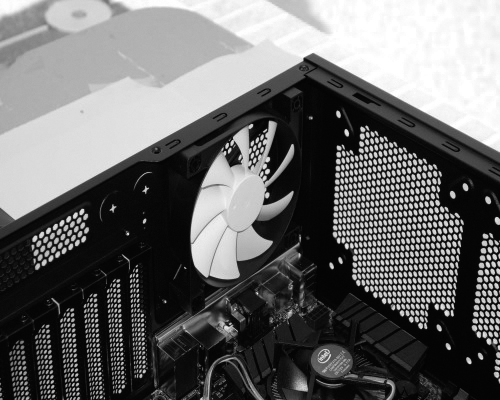
Figure 3-7 Case Fan
CPU heat sink: The CPU generates a lot of heat inside the case. To draw heat away from the CPU core, a heat sink (see Figure 3-8) is installed on top of it. The heat sink has a large surface area with metal fins to dissipate heat into the surrounding air. This is known as passive cooling. Between the heat sink and the CPU is a special thermal compound, which increases the efficiency of heat transfer from the CPU to the heat sink by filling any tiny gaps between the two.

Figure 3-8 CPU Heat Sink
CPU fan: CPUs that are overclocked or running multiple cores tend to generate excessive heat. It is a very common practice to install a fan (see Figure 3-9) on top of the heat sink. The fan moves heat away from the metal fins of the heatsink. This is known as active cooling.

Figure 3-9 CPU Fan
Graphics card cooling system: Other components are also susceptible to heat damage and are often equipped with fans. Video adapter cards have their own processor, called a graphics processing unit (GPU), which generates excessive heat. Video adapter cards also come equipped with one or more fans, as shown in Figure 3-10.
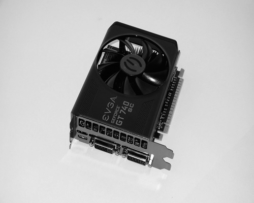
Figure 3-10 Graphics Card Cooling System
Water cooling system: Computers with extremely fast CPUs and GPUs might use a water-cooling system like the one shown in Figure 3-11. A metal plate is placed over the processor, and water is pumped over the top to collect the heat that the processor generates. The water is pumped to a radiator to disperse the heat into the air, and the water is then recirculated. CPU fans make noise and can be annoying at high speeds. An alternative to cooling a CPU with a fan is a method that uses heat pipes. A heat pipe contains liquid that is permanently sealed at the factory and uses a system of cyclical evaporation and condensation.
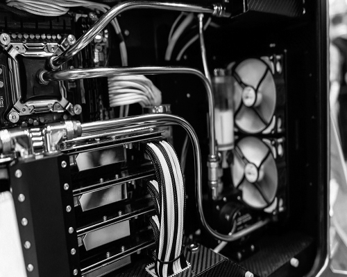
Figure 3-11 Water Cooling System
Check Your Understanding 3.3.1.5: CPU Architectures and Operation
Refer to the online course to complete this activity.
RAID (3.3.2)
Redundant array of independent disks (RAID) can help improve a combination of fault tolerance, storage management, and performance. Different RAID levels have various characteristics that represent different configurations aimed at providing performance/fault tolerance.
What Do You Already Know? - RAID (3.3.2.1)
What do you already know about RAID? These are the RAID characteristics:
Availability
Capacity
Economy
Performance
Redundancy
Reliability
Scenarios
See if you can select the RAID characteristic that would solve the problem described in each of the following six scenarios.
Scenario 1: A user is concerned that the failure of an HDD will cause the loss of important data. What is the correct solution?
Scenario 2: A manager wants to be sure that employees can access the data that they need when they need it.
Scenario 3: HDD data transfer rates have been identified as the cause of work delays.
Scenario 4: A small business has recently grown and is running out of data storage space.
Scenario 5: A company is shopping for larger HDDs and finds them to be too expensive.
Scenario 6: Corrupted data has been causing problems with applications.
Answers
Scenario 1 Answer: Redundancy. This involves having backup resources that can rapidly replace failed devices and lost data or connectivity.
Scenario 2 Answer: Availability. This means IT resources that can be accessed by those who need them at all times.
Scenario 3 Answer: Performance. This is the rate at which tasks can be performed. For storage devices, it is usually the read and write rates, in Mbps.
Scenario 4 Answer: Capacity. This is the amount of data that can be stored.
Scenario 5 Answer: Economy. This is the relative cost of a solution, based on its benefit. Economical things cost less than other things for the capabilities that they offer.
Scenario 6 Answer: Reliability. This is when devices function as intended for a predictable amount of time.
RAID Concepts (3.3.2.2)
With RAID, storage devices can be grouped and managed to create large storage volumes with redundancy. RAID provides a way to store data across multiple storage devices for availability, reliability, capacity, and redundancy and/or performance improvement. In addition, it may be more economical to create an array of smaller devices than it is to purchase a single device with the combined capacity provided by the RAID, especially for very large drives. To the operating system, a RAID array appears as one drive.
The following terms describe how RAID stores data on the various disks:
Striping: This RAID type enables data to be distributed across multiple drives, which provides a significant performance increase. However, because the data is distributed across multiple drives, the failure of a single drive means that all data is lost.
Mirroring: This RAID type stores duplicate data on one or more other drives. This provides redundancy so that the failure of a drive does not cause the loss of data. The mirror can be re-created by replacing the drive and restoring the data from the good drive.
Parity: This RAID type provides basic error checking and fault tolerance by storing checksums separately from data. This enables the reconstruction of lost data without sacrificing speed and capacity, which is a problem with mirroring.
Double parity: This RAID type provides fault tolerance for up to two failed drives.
A large drive enclosure can be used in a data center with one or more RAID implementations. Drive enclosures are specialized enclosures designed to hold and provide power to disk drives while allowing the drives within to communicate to one or more separate computers. Drive enclosures can use hot swappable drives. This means that a drive that fails can be replaced without powering down the entire RAID. Powering down the RAID may make the data on the RAID unavailable to users for an extended period of time. Not all drives and RAID types support hot swapping.
RAID Levels (3.3.2.3)
There are several levels of RAID available. These levels use mirroring, striping, and parity in different ways. Higher levels of RAID, such as RAID 5 or 6, use striping and parity in combination to provide speed and to create large volumes. Table 3-4 provides details about the RAID levels. RAID levels from 10 up combine lower RAID levels. For example, RAID 10 combines RAID 1 and RAID 0 functionalities.
Table 3-4 RAID Levels
RAID Level |
Minimum Number of Drives |
Features |
Advantages |
Disadvantages |
0 |
2 |
Striping |
Performance and capacity. |
All data is lost if one drive fails. |
1 |
2 |
Mirroring |
Performance and reliability. |
Capacity is half of total drive size. |
5 |
3 |
Striping with parity |
Performance, reliability, and capacity. |
It takes time to rebuild the array if a drive fails. |
6 |
3 |
Striping with double parity |
Same as RAID 5 but can tolerate the loss of two drives. |
It takes time to rebuild the array if one or more drives fail. |
10 (0+1) |
4 |
Mirroring and striping |
Performance, capacity, and high reliability. |
Capacity is half of total drive size. |
Check Your Understanding 3.3.2.4: RAID Levels
Refer to the online course to complete this activity.
Ports, Connectors, and Cables (3.3.3)
Many kinds of ports, connectors, and cables are used to attach devices to a computer so they can share data for communication. The main function of a computer port is to act as a point of attachment, where the cable from the peripheral can be connected to allow data to flow to and from the device.
Legacy Ports (3.3.3.1)
Computers have many different types of ports used to connect external peripheral devices. As computer technology has evolved, so have the types of ports used to connect peripheral devices. Legacy ports are typically found on older computers and have been mostly replaced by newer technologies such as USB. The sections that follow describes the various legacy ports.
Serial Ports
Serial ports were used to connect various peripherals such as printers, scanners, and modems. Today, serial ports are sometimes used for making console connections to network devices to perform initial configuration. There are two form factors of serial ports: a 9-pin DB-9 port and a 25-pin port. Figure 3-12 shows a 9-pin DB-9 port.
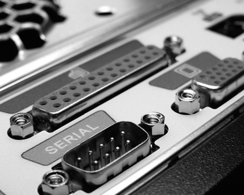
Figure 3-12 Serial Port
Parallel Ports
A parallel ports has a 25-pin receptacle used to connect various peripheral devices, as shown in Figure 3-13. As the name implies, parallel ports send data in multiple bits at once, in parallel communication. Because these ports were often used to connect printers, they are often called printer ports.
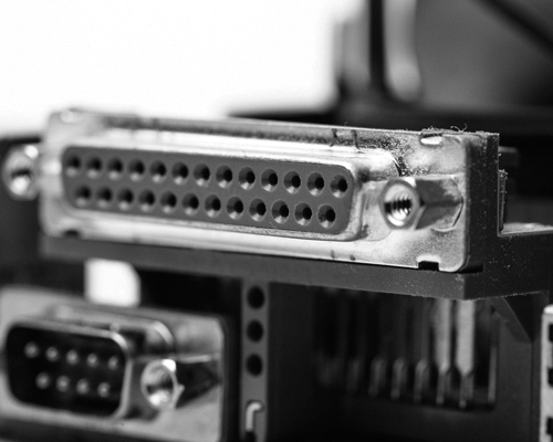
Figure 3-13 Parallel Port
Game Ports
The 15-pin game port (see Figure 3-14) was used as a connector for joystick input. Game ports were originally located on a dedicated game controller expansion card and then later integrated with sound cards and on PC motherboards.

Figure 3-14 Game Port
PS/2 Ports
The PS/2 is a 6-pin din connector used for connecting a keyboard and mouse. Figure 3-15 shows two color-coded PS/2 ports: purple for the keyboard and green for the mouse.

Figure 3-15 PS/2 Ports
Audio Ports
Audio ports (see Figure 3-16) connect audio devices to the computer. Analog ports typically include a line in port to connect to an external source (for example, a stereo system), a microphone port, and line out ports to connect speakers or headphones.

Figure 3-16 Audio Ports
Video and Graphic Ports (3.3.3.2)
Graphic ports are used to connect monitors and external video displays to desktop computers and laptops. The sections that follow describe these ports in greater detail.
VGA Ports
A VGA port (see Figure 3-17) is an analog port and is the oldest graphics port likely still used on some PCs, although it is quickly becoming a legacy technology. A VGA port is colored blue and accepts a 15-pin connector, with the pins arranged in three rows.
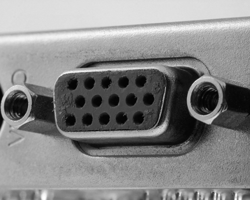
Figure 3-17 VGA Port
DVI Ports
The emergence of digital displays such as LCD monitors and TVs led to the development of DVI for transmitting uncompressed digital video. Variants of the DVI interface are configured to support multiple transmission modes. DVI-A (analog) supports analog only, DVI-D (digital) supports digital only, and DVI-I (integrated) supports both digital and analog. Figure 3-18 shows DVI-I. Two forms of DVI connections exist:
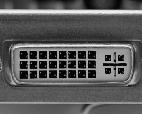
Figure 3-18 DVI-I Port
Single-link connections that use a single Transition Minimized Differential Signaling (TMDS) transmitter
Dual-link connections that use two TMDS transmitters to provide higher resolutions to larger monitors
HDMI Ports
HDMI (see Figure 3-19) carries the same video information as DVI but is also capable of providing digital audio and control signals. HDMI uses a 19-pin connector. Smaller portable electronic devices have a smaller 19-pin mini-HDMI port.
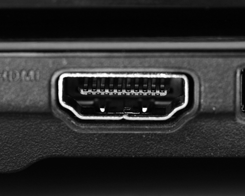
Figure 3-19 HDMI Port
DisplayPort
DisplayPort (see Figure 3-20) is a newer technology designed to replace both DVI and VGA for connecting computer monitors. DisplayPort uses a 20-pin connector for delivering high-bandwidth video and audio signals. As with HDMI, there is a miniaturized version of DisplayPort called Mini DisplayPort; it is primarily used on Apple computers.
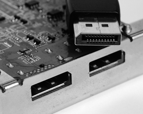
Figure 3-20 DisplayPort
USB Cables and Connectors (3.3.3.3)
The USB protocol has evolved over the years, and the various standards can be confusing. USB 1.0 provided a low-speed transfer rate at 1.5 Mbps for keyboards and mice and a full-speed channel at 12 Mbps. USB 2.0 made a significant leap, increasing transfer rates up to High Speed at 480 Mbps. USB 3.0 increased the transfer rate to SuperSpeed, at 5 Gbps, and USB 3.2, the latest USB-C specification, supports speeds of up to SuperSpeed+, or 20 Gbps. The sections that follow describe and show the various USB cables and connectors.
USB Type-A
USB Type-A, shown in Figure 3-21, is a rectangular connector found on nearly every desktop PC and laptop, as well as TVs, game consoles, and media players. USB 1.1, 2.0, and 3.0 Type-A connectors and receptacles are physically compatible.
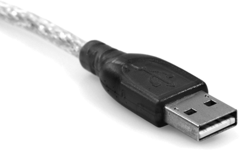
Figure 3-21 USB Type-A
USB Mini-B
The USB Mini-B connector, shown in Figure 3-22, is rectangular with a small indention on each side. The USB Mini-B, also known as mini-USB, form factor is being phased out and replaced by the micro-USB connector.

Figure 3-22 Mini-USB
Micro-USB
The micro-USB connector, shown in Figure 3-23, is found on smartphones, tablets, and other devices. Except for Apple, most manufacturers have adopted the micro-USB interface. The USB 2.0 Micro-B connector has two corners pushed in at an angle.

Figure 3-23 Micro-USB
USB Type-B
The USB Type-B connector, shown in Figure 3-24, is commonly used to connect printer and external hard drives. It has a square shape with beveled exterior corners and an extra notch at the top.

Figure 3-24 USB Type-B
USB Type-C
USB Type-C, shown in Figure 3-25, is the newest USB interface. A USB Type-C connector is smaller than a Type-A connector and is rectangular, with four rounded corners. Both Thunderbolt 3 and USB Type-C are examples of multipurpose cables that can be used to attach different kinds of peripheral devices to a PC. USB Type-C refers to the shape of the port. Thunderbolt 3 combines the functionality of USB, Thunderbolt, and DisplayPort, and it provides the ability to deliver power to devices through the cable.
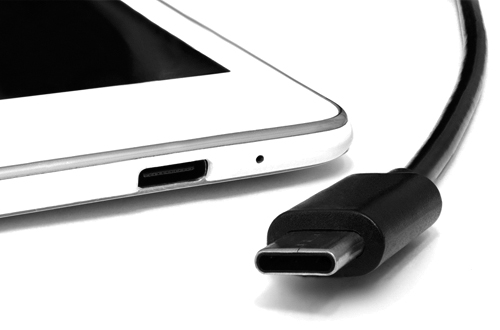
Figure 3-25 USB Type-C
Lightning
The Lightning connector, shown in Figure 3-26, is a small, proprietary 8-pin connector used by Apple mobile devices such as iPhones, iPads, and iPods for both power charging and data transfer. It is similar in appearance to a USB Type-C connector.
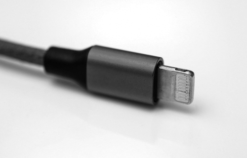
Figure 3-26 Lightning Cable
SATA Cables and Connectors (3.3.3.4)
SATA is an interface type used to connect SATA hard drives and other storage devices to the motherboard inside the computer. SATA cables are long (up to 1 meter) and thin, with a flat and thin 7-pin connector on each end. The sections that follow describe the characteristics and types of SATA cables and connectors.
SATA Cables and Connectors
Figure 3-27 shows a SATA cable. One end plugs into a SATA port on the motherboard, and the other end plugs into the back of an internal storage device such as a SATA hard drive. The SATA connecter has an L-shaped key so that it can be installed only one way.

Figure 3-27 SATA Cable
SATA Data and Power Cables
A SATA data cable does not provide power, and an additional cable is needed to supply power to SATA drives, as shown in Figure 3-28.
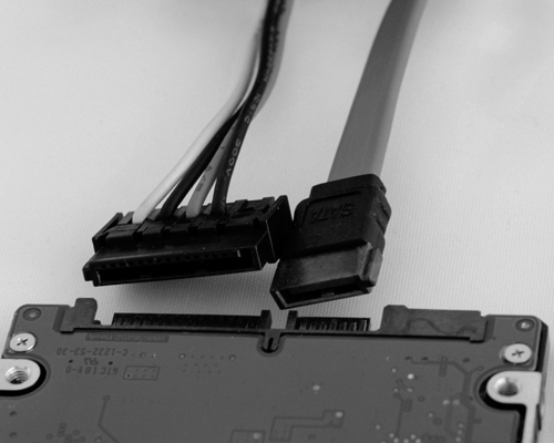
Figure 3-28 SATA Data Cable
eSATA Cables
An eSATA cable, shown in Figure 3-29, is used to connect an external SATA drive. Unlike a SATA connector, an eSATA connector does not have an L-shaped key. However, an eSATA port does have a key feature to prevent inadvertent insertion of a USB connector, which is similar in size and shape.
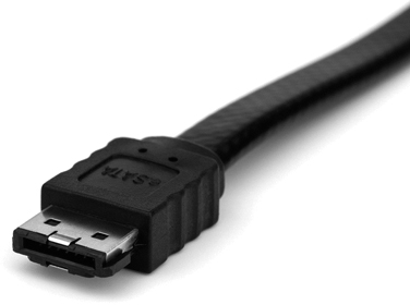
Figure 3-29 eSATA Cable
eSATA Adapter Card
Often, an eSATA adapter card (see Figure 3-30) is installed in a computer to provide eSATA ports.
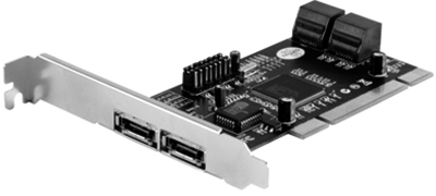
Figure 3-30 eSATA Adapter
Twisted Pair Cables and Connectors (3.3.3.5)
Twisted pair cable is used in wired Ethernet networks and in older telephone networks. Twisted pair cabling gets its name from the fact that pairs of wires inside the cable are twisted together. The twisting of wire pairs helps reduce crosstalk and electromagnetic induction. The sections that follow describe the characteristics and types of twisted pair cables and connectors.
RJ-45 Connectors
Each end of a UTP cable must be terminated with a connector. In the case of Ethernet networks, an RJ-45 connector (see Figure 3-31) terminates the cable and is plugged into an Ethernet port.

Figure 3-31 RJ-45 Connectors
Twisted Pair Cables
There are basically two types of twisted pair cables: unshielded twisted pair (UTP) cabling and shielded twisted pair (STP). The most commonly used form of twisted pair cabling is UTP, shown in Figure 3-31. It consists of color-coded insulated copper wires without the foil or braiding found in STP.
RJ-11 Connectors
Older telephone networks used a four-wire UTP cable with two wire pairs terminated with a 6-pin RJ-11 connector, shown in Figure 3-32. The RJ-11 connector looks very similar to the RJ-45 connector but is smaller.

Figure 3-32 RJ-11 Connector
Coax Cables and Connectors (3.3.3.6)
Coaxial (coax) cable has an inner center conductor, usually made from copper or copper-clad steel, which is surrounded by a nonconductive dielectric insulating material. The dielectric is surrounded by a foil shield, which forms the outer conductor and shields against electromagnetic interference (EMI). The outer conductor/shield is encased in a PVC outer jacket. The sections that follow describe the characteristics and types of coax cables and connectors.
Coax Cable Construction
The coax cable in Figure 3-33 has the outer jacket pulled back to reveal the braided shielding and copper core conductor.

Figure 3-33 Coax Cable
RG-6
An RG-6 cable (see Figure 3-34) cable is heavy gauge and has insulation and shielding tuned for high-bandwidth, high-frequency applications such as Internet, cable TV, and satellite TV signals.
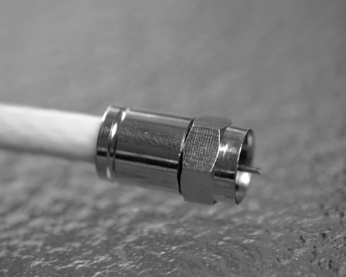
Figure 3-34 RG-6 Cable
RG-59
RG-59 cable is thinner and is recommended in low-bandwidth and lower-frequency applications, such as analog video and CCTV applications, such as for the camera in Figure 3-35.
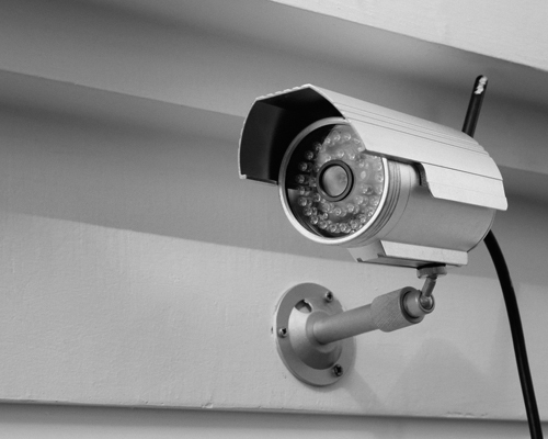
Figure 3-35 RG-59 Cable
BNC
A BNC (Bayonet Neill–Concelman) connector, shown in Figure 3-36, connects coaxial cables to devices using a quarter-turn connection scheme. BNC is used with digital or analog audio or video.
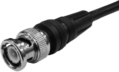
Figure 3-36 BNC Connector
SCSI and IDE Cables and Connectors (3.3.3.7)
Small Computer System Interface (SCSI) is a standard for connecting peripheral and storage devices. SCSI is a bus technology, meaning that all devices connect to a central bus and are “daisy-chained” together. The cabling/connector requirements depend on the location of the SCSI bus.
Integrated Drive Electronics (IDE) is a standard type of interface used to connect some hard drives and optical drives to each other and to the motherboard.
The sections that follow describe the characteristics and types of SCSI and IDE cables and connectors.
External SCSI Cables
A Centronics connector (see Figure 3-37) is used for connecting older external SCSI devices such as scanners and printers. This connector comes in 36-pin and 50-pin versions, with the pins arranged in two rows and a plastic bar through the center that holds the contact pins. Squeeze latches or bail locks located on the sides of the connector are used to hold it in place.

Figure 3-37 External SCSI Cable
Internal SCSI Cables
A common SCSI connector for internal hard drives is the internal 50-pin SCSI, which has 50 pins arranged in two rows and is attached to a ribbon cable, as shown in Figure 3-38.
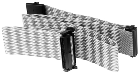
Figure 3-38 Internal SCSI Cable
IDE Cables
IDE ribbon cables, shown in Figure 3-39, look very similar to internal SCSI cables; however, IDE uses 40-pin connectors. There are typically three connectors on the cable: one to connect to the IDE port on the motherboard and two for attachment of IDE drives.

Figure 3-39 IDE Cable
Check Your Understanding 3.3.3.8: Identify the External Connectors
Refer to the online course to complete this activity.
Monitors (3.3.4)
A monitor is an output device that connects by cable to a port on the graphics card. It displays the results of user input. There are different types of monitors, and the two primary types are cathode ray tube (CRT) and liquid crystal display (LCD).
Monitor Characteristics (3.3.4.1)
There are many types of computer monitors available. Some are designed for casual use, and others are for specific requirements, such as those used by architects, graphic designers, or gamers.
Monitors vary by use, size, quality, clarity, brightness, and other factors. Therefore, it is useful to understand the various terms used when discussing monitors.
Computer monitors are usually described in terms of the following:
Screen size: This is the diagonal measurement of the screen (such as from top left to bottom right), in inches. Common sizes include 19 to 24 inches, to ultrawide monitors that are 30 or more inches wide. Larger monitors are usually better but are more expensive and require more desk space.
Resolution: Resolution is measured by the number of horizontal and vertical pixels. For example, 1920×1080 (called 1080p) is a common resolution. It means the monitor has 1920 horizontal pixels and 1080 vertical pixels.
Monitor resolution: This relates to the amount of information that can be displayed on a screen. A higher-resolution monitor displays more information on a screen than a lower-resolution monitor does. This is true even with monitors that have the same screen size.
Native resolution: This identifies the best monitor resolution for the specific monitor. In Windows 10, the native resolution of a monitor is identified by the keyword (Recommended) beside the monitor resolution. For example, in Figure 3-40, the native resolution of the monitor is 1920×1080.

Figure 3-40 Native Resolution
Native mode: This term describes the image sent to the monitor by the video adapter card matching the native resolution of the monitor.
Connectivity: Older monitors used VGA or DVI connectors, and newer monitors support HDMI and DisplayPort ports. DisplayPort is a connection found on newer monitors. It supports higher resolutions and high refresh rates.
Note
If you want to display more things on the screen, select a higher-resolution monitor. If you just want things to appear bigger, select a larger screen size.
Monitor Terms (3.3.4.2)
Table 3-5 lists the most common monitor-related terms.
Table 3-5 Technical Monitor Terms
Monitor Term |
Description |
Abbreviation for “picture element,” a tiny dot capable of displaying the shades red, green, and blue (RGB). With more pixels, a monitor can display more detail. |
|
The distance between pixels on the screen. A lower dot pitch (that is, a smaller distance between dots) produces a better image. |
|
The luminance of a monitor, measured in candelas per square meter (cd/m2). Brightness up to 250 cd/m2 is typically recommended, but in well-lit rooms, you may use up to 350 cd/m2. Keep in mind that too much brightness may cause eyestrain. |
|
A measurement of how white and how black a monitor can get. A contrast ratio of 1000:1 displays dimmer whites and more pale blacks than 4500:1. |
|
The horizontal-to-vertical measurement of the viewing area of a monitor. For example, QSXGA measures 2560 pixels horizontally by 2048 pixels vertically, which creates an aspect ratio of 5:4. If a viewing area is 16 inches wide by 12 inches high, the aspect ratio is 4:3. A viewing area that is 24 inches wide by 18 inches high also has an aspect ratio of 4:3. |
|
How often per second an image is rebuilt, expressed in Hertz (Hz). A higher refresh rate produces a better image and is recommended for gamers. |
|
The amount in time for a pixel to change properties (such as color or brightness). Fast response times display a smooth image when displaying fast action. |
|
Interlaced/non-interlaced |
The type of scanning a monitor uses. Interlaced monitors create an image by scanning the screen two times. The first scan covers the odd lines, top to bottom, and the second scan covers the even lines. Non-interlaced monitors create the image by scanning the screen, one line at a time, from top to bottom. |
Display Standards (3.3.4.3)
Over the years, many different display standards have been developed, as shown in Table 3-6.
Table 3-6 Legacy and Common Monitor Display Standards
Monitor Standard |
Resolution |
Aspect Ratio |
Comments |
320×200 |
16:10 |
|
|
VGA |
640×480 |
4:3 |
|
800×600 |
4:3 |
|
|
HD |
1280×720 |
16:9 |
|
FHD |
1920×1080 |
16:9 |
|
QHD |
2560×1440 |
16:9 |
|
UHD |
3840×2160 |
16:9 |
|
Using Multiple Monitors (3.3.4.4)
Adding monitors can increase your visual desktop area and improve productivity. The added monitors enable you to expand the size of the monitor or duplicate the desktop so you can view additional windows. For example, the woman in Figure 3-41 is using multiple displays. She is using the monitor on the right to make changes to a website and the monitor on the left to display the resulting changes. She is also using a laptop to display a library of images she is considering for inclusion in the website.

Figure 3-41 Using Multiple Monitors
Many computers have built-in support for multiple monitors. To connect multiple monitors to a computer, you need the supporting cables. You also need to enable your computer to support multiple monitors.
For example, on a Windows 10 host, right-click anywhere on the Desktop and choose Display settings. Windows should open the Display window, as shown in Figure 3-42. In the example, the user has two monitors connected in the configuration displayed. The current monitor selected is highlighted in blue and has a resolution of 1920×1080. It is also the main display monitor. By clicking on monitor 1 or 2 you could see the resolution of that monitor.
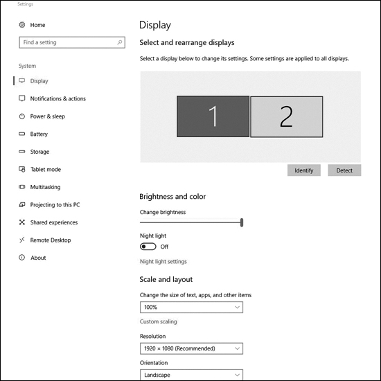
Figure 3-42 Enabling Dual Monitors on a Windows Host
Check Your Understanding 3.3.4.5: Monitor Terminology
Refer to the online course to complete this activity.
Computer Configuration (3.4)
Necessary changes to a computer may require an upgrade or replacement of components and peripherals. Research the effectiveness and cost for both upgrading and replacing. As a technician, it is important to understand the system usage and user needs as well as how computer components work together to upgrade or build a functioning PC with the right purpose.
Upgrade Computer Hardware (3.4.1)
When upgrading a computer, component compatibility is important. When you are adding new or additional components to an existing build, to ensure that the system continues to run efficiently after the upgrade, you need to choose the right components. Software upgrade compatibility is just as necessary as hardware compatibility.
Motherboard Upgrade (3.4.1.1)
Computers need periodic upgrades for various reasons:
User requirements change.
Upgraded software packages require new hardware.
New hardware offers enhanced performance.
Changes to a computer may lead you to upgrade or replace components and peripherals. Research the effectiveness and cost of both upgrading and replacing.
If you upgrade or replace a motherboard, consider that you might have to replace other components, including the CPU, the heat sink and fan assembly, and RAM. A new motherboard must also fit into the old computer case, and the power supply must support it.
When upgrading the motherboard, if the CPU and the heat sink and fan assembly are to be reused, move them to the new motherboard. These items are much easier to work with when they are outside the case. Work on an antistatic mat and wear antistatic gloves or an antistatic wrist strap to avoid damaging the CPU. If the new motherboard requires a different CPU and RAM, install them at this time. Clean the thermal compound from the CPU and heat sink. Remember to reapply thermal compound between the CPU and the heat sink.
Steps to Upgrade a Motherboard (3.4.1.2)
Before beginning an upgrade, ensure that you know where and how everything is connected. Always make notes in a journal to record how the computer is originally set up. A quick way is to use a cell phone to take pictures of important items, such as how components connect to the motherboard. These pictures may be very helpful during reassembly.
To upgrade a motherboard from a computer case, follow these steps:
Step 1. Record how the power supply, case fans, case LEDs, and case buttons attach to the old motherboard.
Step 2. Disconnect the cables from the old motherboard.
Step 3. Disconnect the expansion cards from the case. Remove each expansion card and place all the cards in antistatic bags or on an antistatic mat.
Step 4. Carefully record how the old motherboard is secured to the case. Some mounting screws provide support, and some provide an important grounding connection between the motherboard and chassis. In particular, pay attention to screws and standoffs that are non-metallic because they may be insulators. Replacing insulating screws and supports with metal hardware that conducts electricity might damage electrical components.
Step 5. Remove the old motherboard from the case.
Step 6. Examine the new motherboard and identify where all the connectors are, such as power, SATA, fan, USB, audio, front panel connector, and any others.
Step 7. Examine the I/O shield located at the back of the computer case. Replace the old I/O shield with the I/O shield that comes with the new motherboard.
Step 8. Insert and secure the motherboard into the case. Be sure to consult the case and motherboard manufacturer’s user guides. Use the proper types of screws. Do not swap threaded screws with self-tapping metal screws, which would damage the threaded screw holes and might not be secure. Make sure the threaded screws are the correct length and have the same number of threads per inch. If the thread of screws is correct, they fit easily. If you force a screw to fit, you can damage the threaded hole, and it will not hold the motherboard securely. Using the wrong screw can also produce metal shavings that can cause short circuits.
Step 9. Connect the power supply, case fans, case LEDs, front panel, and any other required cables. If the ATX power connectors are not the same size (some have more pins than others), you might need to use an adapter. Refer to the motherboard documentation for the layout of these connections.
Step 10. After the new motherboard is in place and the cables are connected, install and secure the expansion cards.
It is now time to check your work. Make sure that there are no loose parts or unconnected cables. Connect the keyboard, mouse, monitor, and power. If a problem is detected, shut off the power supply immediately.
CPU Upgrade (3.4.1.3)
One way to increase the power of a computer is to increase the processing speed. You can do this by upgrading the CPU (see Figure 3-43). The CPU must meet the following requirements:
The new CPU must fit into the existing CPU socket.
The new CPU must be compatible with the motherboard chipset.
The new CPU must operate with the existing motherboard and power supply.
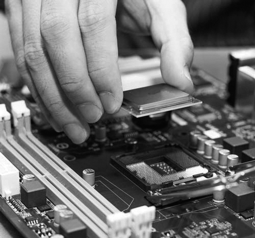
Figure 3-43 Installing a New CPU
The new CPU might require a different heat sink and fan assembly. The assembly must physically fit the CPU and must be compatible with the CPU socket. It must also be adequate to remove the heat of the faster CPU.
Caution
You must apply thermal compound between the new CPU and the heat sink and fan assembly.
View thermal settings in the BIOS to determine if there are any problems with the CPU and the heat sink and fan assembly. Third-party software applications can also report CPU temperature information in an easy-to-read format. Refer to the motherboard or CPU user documentation to determine if the chip is operating in the correct temperature range.
To install additional fans in the case to help cool the computer, follow these steps:
Step 1. Align each fan so that it faces the correct direction to either draw air in or blow air out.
Step 2. Mount each fan using the predrilled holes in the case. It is common to mount fans near the top of the case to blow hot air out and near the bottom of the case to bring air in. Avoid mounting two fans close together if they are moving air in opposite directions.
Step 3. Connect the fan to the power supply or the motherboard, depending on the case fan plug type.
Storage Device Upgrade (3.4.1.4)
Instead of purchasing a new computer to get faster speed and more storage space, you might consider adding another hard drive (see Figure 3-44).

Figure 3-44 Installing a New Drive
There are several reasons for installing an additional drive, including the following:
To increase storage space
To increase hard drive speed
To install a second operating system
To store the system swap file
To provide fault tolerance
To back up the original hard drive
After selecting the appropriate hard drive for the computer, follow these general guidelines for installation:
Step 1. Place the hard drive in an empty drive bay and tighten the screws to secure the hard drive.
Step 2. Connect the drive to the motherboard, using the correct cable.
Step 3. Attach the power cable to the drive.
Peripheral Upgrades (3.4.1.5)
Peripheral devices periodically need to be upgraded. For example, if a device stops operating or if you wish to improve performance and productivity, an upgrade might be necessary.
These are a few reasons for upgrading a keyboard and/or a mouse:
You might want use a keyboard and mouse with an ergonomic design, such as those shown in Figure 3-45. Ergonomic devices are made to be more comfortable to use and to help prevent repetitive motion injuries.
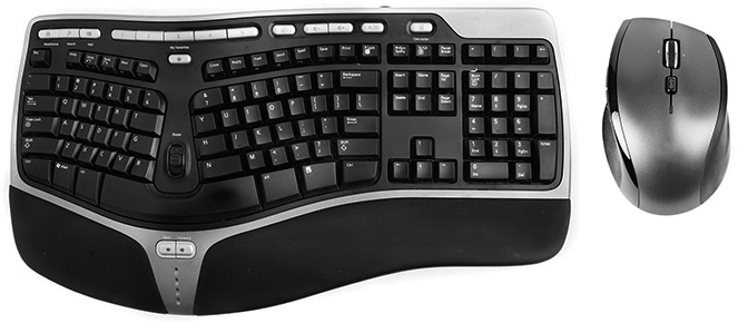
Figure 3-45 Ergonomic Keyboard and Mouse
You might want to reconfigure the keyboard to accommodate a special task, such as typing in a second language with additional characters.
You might need to accommodate users with disabilities.
Sometimes, however, it is not possible to perform an upgrade using the existing expansion slots or sockets. In this case, you might be able to accomplish the upgrade by using a USB connection. If the computer does not have an extra USB connection, you must install a USB adapter card or purchase a USB hub, such as the one shown in Figure 3-46.

Figure 3-46 USB Hub
Power Supply Upgrade (3.4.1.6)
Upgrading your computer hardware will most likely also change its power needs. If so, you might need to upgrade your power supply. You can find calculators on the Internet to help you determine whether you need to upgrade the power supply. Search for “power supply wattage calculator.”
Lab 3.4.1.7: Research a Hardware Upgrade
![]()
In this lab, you will gather information about hardware components so you can upgrade a computer’s hardware so the customer can play advanced video games.
Configurations for Specialized Computers (3.4.2)
Most computers are general-purpose computers built to process a variety of tasks and operations. Specialized computers refer to computers built to perform specific tasks.
What Do You Already Know? - Configure a CAx Workstation (3.4.2.1)
One type of specialized computer is a workstation used to run computer-aided design (CAD) or computer-aided manufacturing (CAM) software.
A CAD or CAM (CAx) workstation is used to design products and control the manufacturing process. CAx workstations are used to create blueprints and to design homes, cars, airplanes, computers, and many of the parts in the products that you use every day. A computer used to run CAx software must support the needs of the software and the I/O devices that the user needs to design and manufacture products. CAx software is often complex and requires robust hardware.
What do you already know about configuring CAx workstations?
Video Card
What type of video card would you choose for a CAx workstation?
On-board
Basic
High-end
Powerful
Answer: You should choose a high-end video card. High-resolution graphic cards perform fast rendering of 2D and 3D graphics, using specialized GPUs. Also, multiple monitors are desired, or even required, so that the user can work with code, 2D renderings, and 3D models all at the same time. The other options are not appropriate for the following reasons:
On-board video does fine for very basic tasks, such as web browsing and desktop applications, but it would struggle to perform CAx applications, if it could perform any at all.
A basic video card might be able to run some CAx applications, but it would be slow and most likely low resolution.
A powerful video card would run most CAx applications, but it might not be able to perform very well, or it might not provide a high enough resolution.
RAM
What type of RAM would you choose for a CAx workstation?
Maximum
Standard
Minimum
Answer: Maximum. Because of the high amount of data processed by a CAx workstation, RAM is very important. The more RAM that is installed, the more data the processor can calculate before needing to read from slower hard drives. Install the maximum amount of memory supported by the motherboard and the operating system. The amount and speed of the memory should exceed the minimums recommended by the CAx application. The other options are not appropriate for the following reasons:
The minimum amount of RAM needed by the application will provide only basic functionality.
A standard amount of memory would not allow the application to work at its potential. The application would need to read from slower storage drives often.
Storage
What type of storage would you choose for a CAx workstation?
Basic
SSD
RAID
Large and fast
Answer: SSD. An SSD drive has no moving parts and improves the performance of a computer dramatically. Over time, SSD drives have increased storage capacity and become much more affordable. SSD is the best choice for this application. The other options are not appropriate for the following reasons:
A basic hard drive would not meet this need. A CAx workstation often works with very large files.
Some types of RAID configuration would increase read and write performance, but this can be costly.
Large and fast storage would work, but a lot of time would be lost reading and writing by using this type.
What Do You Already Know? - Configure an Audio Video Editing Workstation (3.4.2.2)
An audio editing workstation is used to record music, create music CDs, and create CD labels. A high-end video editing workstation can be used to create television commercials, prime-time programming, movies for the theater, or home movies.
Specialized hardware and software are combined to build a computer to perform audio and video editing. Audio software on an audio editing workstation is used to record audio, manipulate how the audio sounds through mixing and special effects, and finalize recordings for publication. Video software is used to cut, copy, combine, and change video clips. Special effects are also added to video using video software.
What do you already know about configuring audio and video editing workstations?
Video Card
What type of video card would you choose for an audio and video editing workstation?
On-board
Specialized
Powerful
Basic
Answer: Specialized. A video card that can handle high resolutions and multiple displays is necessary to combine and edit different video feeds and special effects in real time. You must understand the needs of the customer and research video cards and then install a card that can handle the large amounts of information that come from modern cameras and effects equipment. The other options are not appropriate for the following reasons:
On-board video does fine for very basic tasks such as web browsing and desktop applications, but it would struggle with video feeds and special effects.
A powerful video card would be able to handle many video feeds and some special effects, but it might not be able to perform very well or provide a high enough resolution.
A basic video card might be able to handle more than one video feed, but it would be slow and most likely low resolution.
Audio Card
What type of audio card would you choose for an audio and video editing workstation?
On-board
Specialized
Basic
Answer: Specialized. When recording music to a computer in a studio, multiple inputs from microphones and many outputs to effects equipment might be needed. An audio card capable of handling all these inputs and outputs is needed. Research different audio card manufacturers and understand the needs of your customer to install an audio card that will meet all the needs of a modern recording or mastering studio. The other options are not appropriate for the following reasons:
On-board sound may offer things like microphone input and surround sound, but it would not offer the inputs and outputs needed when recording music, for example.
A basic sound card will have better sound than on-board sound, and it may offer a few inputs and outputs, but it will not be able to meet the needs of this type of computer.
Storage
What type of storage would you choose for an audio and video editing workstation?
Basic
Large and fast
RAID
SSD
Answer: Large and fast. Modern video cameras record in high resolution at fast frame rates. This translates into a large amount of data. Small hard drives will fill up very quickly, and slow hard drives will not be able to keep up with demands—and they may even drop frames at times. A large, fast hard drive such as an SSD or SSHD drive is recommended to record high-end video without errors or missed frames. The other options are not appropriate for the following reasons:
An audio/video editing workstation often works with very large files. A basic hard drive would not meet this need.
RAID levels such as 0 or 5, where striping is used, can help increase read or write speeds but not enough for this purpose.
Audio and video files take up enormous amounts of space. SSD would be too costly until prices drop dramatically.
Monitor
What type of monitor would you choose for an audio and video editing workstation?
Basic
Multiple
Widescreen
Answer: Multiple. When working with audio and video, two, three, or even more monitors can be very helpful to keep track of everything that is going on with multiple tracks, scenes, equipment, and software. HDMI, DisplayPort, and Thunderbolt cards are recommended, and DVI is acceptable. If multiple monitors are required, specialized video cards are necessary when building an audio or video workstation. The other options are not appropriate for the following reasons:
A basic monitor would not be able to display everything necessary when editing video.
A widescreen monitor would display more than a basic monitor but not enough to perform all the tasks necessary with video editing and special effects.
What Do You Already Know? - Configure a Virtualization Workstation (3.4.2.3)
You might need to build a computer for a customer who uses virtualization technologies. Simultaneously running two or more operating systems on one computer is called virtualization. Often, an operating system is installed, and virtualization software is used to install and manage additional installations of other operating systems. Different operating systems from multiple software companies may be used.
Another type of virtualization, called Virtual Desktop Infrastructure (VDI), allows users to log in to a server to access virtual computers. Input from the mouse and keyboard is sent to the server to manipulate the virtual computer. Output such as sound and video is sent back to the speakers and the display of the client accessing the virtual computer.
Low-powered thin clients use a server that is much more powerful to perform difficult calculations. Laptops, smartphones, and tablets can also access VDI to use virtual computers. These are some other uses of virtual computing:
Testing software or software upgrades in an environment that does not hurt the current operating system environment
Using more than one type of operating system on one computer, such as Linux or macOS
Browsing the Internet without harmful software hurting the main installation
Running old applications that are not compatible with modern operating systems
Virtual computing requires more powerful hardware configurations because each installation needs its own resources. One or two virtual environments can be run on a modern computer with modest hardware, but a complete VDI installation may require fast, expensive hardware to support multiple users in many different environments.
What do you already know about configuring a virtualization workstation?
Processor
What type of processor would you choose for a virtualization workstation?
Basic
Fast
Multi-core
Answer: Multi-core. Although a single-core CPU can perform virtual computing, a CPU with additional cores increases speed and responsiveness when hosting multiple users and virtual machines. Some VDI installations use computers that have many CPUs with multiple cores. The other options are not appropriate for the following reasons:
A basic processor may be able to run a virtual computer, but it would not be able to handle multiple VDI installations.
A fast processor may be able to handle more than one virtual computer or many VDI installations, but it would limit the performance.
RAM
What type of RAM would you choose for a virtualization workstation?
Standard
Maximum
Minimum
Answer: Maximum. You need enough RAM to meet the requirements of each virtual environment and the host computer. A standard installation using only a few virtual machines might require as little as 1 GB of RAM to support a modern operating system such as Windows 8. With multiple users, supporting many virtual computers for each user, you might need to install 64 GB of RAM or more. The other options are not appropriate for the following reasons:
A standard amount of memory would not allow the virtual computers to work at their potential. It also would not allow very many virtual computers to run at the same time.
Using the minimum amount of RAM needed by the virtualization application will provide one or only a few virtual computers, because virtualizing computers requires more powerful hardware configurations since each installation needs its own resources.
What Do You Already Know? - Configure a Gaming PC (3.4.2.4)
Many people enjoy playing computer games. Each year, games become more advanced and require more powerful hardware, new hardware types, and additional resources to ensure a smooth and enjoyable gaming experience.
What do you already know about configuring a gaming PC?
Video Card
What type of video card would you choose for a gaming PC?
On-board
High-end
Powerful
Basic
Answer: High-end. Modern games use high resolutions and intricate detail. A video card that has a fast, specialized GPU and large amounts of fast video memory is necessary to ensure that the images displayed on the monitor are high quality, clear, and smooth. Some gaming machines use multiple video cards to produce high frame rates or make it possible to use multiple monitors. The other options are not appropriate for the following reasons:
On-board video does fine for very basic tasks, such as web browsing and desktop applications, but it would struggle to display games at even low frame rates.
A powerful video card would run most games, but it might not be able to perform very well or provide a high enough resolution.
A basic video card might be able to run some games, but it would be slow and most likely low resolution.
Audio Card
What type of audio card would you choose for a gaming PC?
Specialized
On-board
Basic
Answer: Specialized. Video games use multiple channels of high-quality sound to immerse the player in the games. A high-quality sound card increases the quality of sound above that of built-in sound on a computer. A dedicated sound card also helps improve overall performance by taking some of the demand off the processor. Gamers often use specialized headphones and microphones to interact with other online gamers. The other options are not appropriate for the following reasons:
On-board sound might offer options such as microphone input and surround sound but often at low quality.
A basic soundcard will have better sound than on-board sound, and it may offer a few inputs and outputs, but gamers want to be immersed in their games.
Storage
What type of storage would you choose for a gaming PC?
Basic
Large and fast
RAID
SSD
Answer: SSD. An SSD drive has no moving parts and improves the performance of a computer dramatically. Over time, SSD drives have increased storage capacity and become much more affordable. SSD drives are more expensive, but they improve the performance of games dramatically. The other options are not appropriate for the following reasons:
A gaming computer needs to keep up with the fast pace of games. A basic drive would not meet this need.
Large and fast storage would work, but a lot of time would be lost reading and writing by using this type.
Some types of RAID configuration would increase read and write performance but not enough to meet this need.
Cooling
What type of cooling would you choose for a gaming PC?
Passive
High-end
Active
Answer: High-end. High-end components often produce more heat than standard components. More robust cooling hardware is often needed to make sure the computer stays cool under heavy loads while playing advanced games. Oversized fans, heat sinks, and liquid cooling devices are often used to keep CPUs, GPUs, and RAM cool. The other options are not appropriate for the following reasons:
Passive cooling is used to keep noise at a minimum for computers such as home theater PCs. A gaming PC would overheat using passive cooling.
Active cooling might work for some gaming PCs, but high-end computers can produce more heat than standard active cooling can handle.
Check Your Understanding 3.4.2.5: Specialized Computer Component Types
Refer to the online course to complete this activity.
Thick and Thin Clients (3.4.2.6)
Computers are sometimes referred to as thick and thin clients:
Thick clients: Sometimes called fat clients, these are the standard computers that we have discussed in this chapter. The computers have their own operating system, a multitude of applications, and local storage. They are standalone systems and do not require a network connection to operate. All the processing is performed locally on the computer.
Thin clients: These are typically low-end network computers that rely on remote servers to perform all data processing. Thin clients require a network connection to a server and usually access resources using a web browser. However, the client can be a computer running thin client software or a small, dedicated terminal consisting of a monitor, keyboard, and mouse. Typically the clients do not have any internal storage and have very few local resources.
Table 3-7 identifies differences between thick and thin clients.
Table 3-7 Thick and Thin Clients
Characteristic |
Thick Clients |
Thin Clients |
Resources required |
Monitor, mouse, keyboard, tower (with CPU and RAM), internal storage |
Monitor, mouse, keyboard, small computer |
Footprint |
Large |
Small |
Network access |
Optional |
Required |
Data processing performed |
Locally on computer |
Remotely on servers |
Effort to deploy corporately |
More |
Less |
Cost to deploy corporately |
More |
Less |
Applications |
Locally installed desktop applications |
Not locally installed; interfaces with applications that run on a server |
Hardware requirements |
Recommended requirements or better for installing Windows and any software applications |
Only minimum requirements for installing Windows |
Along with thick and thin clients, there are computers that are built for specific purposes. A computer technician is responsible for evaluating, selecting appropriate components, and upgrading or custom-building specialized computers to meet the needs of customers.
This section identifies and discusses some of these specialized computers.
NAS (3.4.2.7)
Network-attached storage (NAS) devices, such as the one shown in Figure 3-47, are servers that are connected to a network to provide file-level data storage to clients. This specialized computer is sometimes single-purposed, running a stripped-down operating system to perform only the function of file serving. Sometimes the device can offer additional functionality, such as media streaming, network services, automated backup functions, website hosting, and many other services.
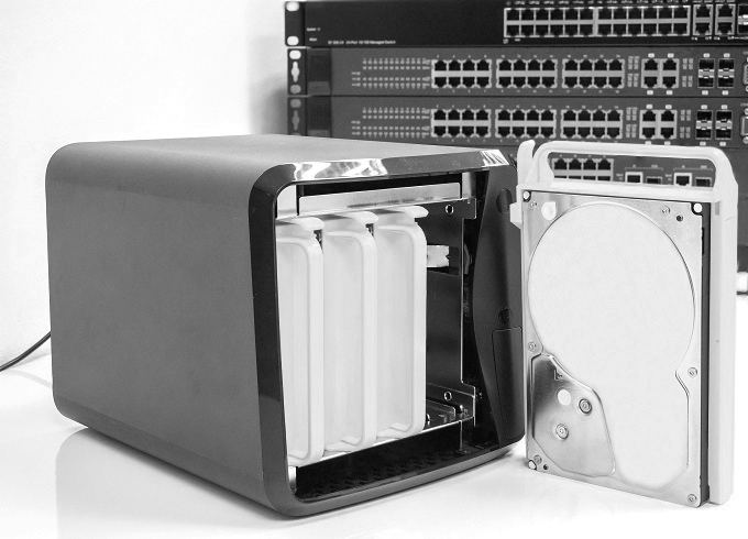
Figure 3-47 NAS Device
A NAS may offer high-speed networking through the use of a gigabit network interface card (NIC). This interface allows many simultaneous connections to the network at very high speed. Some NAS devices have more than one gigabit NIC to allow many more connections.
Recommended practice dictates using a special hard drive when deploying a NAS device. These drives are specially built to endure the always-on environment of a NAS system. It is very common to find multiple drives within a NAS not only to provide additional storage but also to provide either increased speed or redundancy through the use of RAID.
Protecting the Environment (3.5)
There are multiple reasons you need be aware of how to protect your environment as a computer technician, such as complying with local, state, and federal government disposal regulations to avoid receiving serious fines and aiding in the prevention of harm to the ecosystem.
Safe Disposal of Equipment and Supplies (3.5.1)
Proper disposal of equipment and supplies is important to the health of an organization and the planet. Be aware of current local, regional, and national laws. Find reputable recyclers but be sure to wipe the data off your device before you recycle it and investigate the best method of disposal for all equipment. Improper disposal not only harms the environment but could pose other serious consequences to your business.
Safe Disposal Methods (3.5.1.1)
After upgrading a computer or replacing a broken device, what do you do with the leftover parts? If the parts are still good, they can be donated or sold. Parts that no longer work must be disposed of, but they must be disposed of responsibly.
The proper disposal or recycling of hazardous computer components is a global issue. Make sure to follow regulations that govern how to dispose of specific items. Organizations that violate these regulations can be fined or may face expensive legal battles. Regulations for the disposal of the items listed in the following sections vary from state to state and from country to country. Check with your local environmental regulatory agency.
Batteries
Batteries often contain rare earth metals that can be harmful to the environment. These metals do not decay and remain in the environment for many years. Mercury is commonly used in the manufacturing of batteries and is extremely harmful to humans.
Recycling batteries should be standard practice. All batteries are subject to disposal procedures that comply with local environmental regulations.
Monitors
Handle CRT monitors with care. Extremely high voltage can be stored in CRT monitors, even the monitors that have been disconnected from a power source.
Monitors contain glass, metal, plastics, lead, barium, and rare earth metals. According to the U.S. Environmental Protection Agency (EPA), monitors can contain approximately 4 pounds of lead. Monitors must be disposed of in compliance with environmental regulations.
Toner Kits, Cartridges, and Developers
Used printer toner kits and printer cartridges must be disposed of properly, in compliance with environmental regulations. They can also be recycled. Some toner cartridge suppliers and manufacturers take empty cartridges for refilling. Kits to refill inkjet printer cartridges are available but are not recommended because the ink might leak into the printer, causing irreparable damage. Using refilled inkjet cartridges might also void the inkjet printer warranty.
Chemical Solvents and Aerosol Cans
Contact the local sanitation company to learn how and where to dispose of the chemicals and solvents used to clean computers. Never dump chemicals or solvents down a sink or dispose of them in a drain that connects to public sewers.
Cell Phones and Tablets
The EPA recommends that individuals check with local health and sanitation agencies for their preferred way to dispose of electronics such as cell phones, tablets, and computers. Most computer equipment and mobile devices contain hazardous materials, such as heavy metals, that do not belong in a landfill because they contaminate the earth. Local communities may also have recycling programs.
Safety Data Sheets (3.5.1.2)
Hazardous materials are sometimes called toxic waste. These materials can contain high concentrations of heavy metals such as cadmium, lead, or mercury. The regulations for the disposal of hazardous materials vary by state or country. Contact the local recycling or waste removal authorities in your community for information about disposal procedures and services.
A safety data sheet (SDS), formerly known as a material safety and data sheet (MSDS), is a fact sheet that summarizes information about material identification, including hazardous ingredients that can affect personal health, fire hazards, and first-aid requirements. An SDS contains chemical reactivity and incompatibility information. It also includes protective measures for the safe handling and storage of materials and spill, leak, and disposal procedures. To determine whether a material is classified as hazardous, consult the manufacturer’s SDS, which in the U.S. is required by OSHA when the material is transferred to a new owner.
The SDS explains how to dispose of potentially hazardous materials in the safest manner. Always check local regulations concerning acceptable disposal methods before disposing of any electronic equipment.
In the European Union, the regulation Registration, Evaluation, Authorization and Restriction of Chemicals (REACH) came into effect June 1, 2007, replacing various directives and regulations with a single system.
Check Your Understanding 3.5.1.3: Safe Disposal
Refer to the online course to complete this activity.
Summary (3.6)
In this chapter, you learned about the computer boot process and the role played by the BIOS, which performs the POST on the main components of the computer. You also learned that the motherboard BIOS settings are saved in a CMOS memory chip. When a computer boots, the BIOS software reads the configured settings stored in CMOS to determine how to configure the hardware. In a lab, you installed Microsoft Windows operating system and third-party software.
After installing Windows, you learned about wattage and voltage and Ohm’s law, which expresses the idea that voltage is equal to the current multiplied by the resistance (V = IR) and that power is equal to the voltage multiplied by the current (P = VI). You learned about the types of AC power fluctuations that can cause data loss or hardware failures such as blackouts, brownouts, noise, spikes, and power surges. You also learned about the devices that help shield against power fluctuation problems and protect the data and computer equipment. These devices include surge protectors, UPSs, and SPSs.
Next, you learned about multicore processors ranging from dual-core CPUs with two cores inside a single CPU, to octa-core CPUs with eight cores inside a single CPU, and different types of CPU cooling mechanisms, including fans, heat sinks, and water cooling systems. You also learned how multiple drives can be logically grouped and managed to create large storage volumes with redundancy using RAID technology. Striping, mirroring, parity, and double parity types of RAID were covered.
You learned about many different types of computer ports and connectors, starting with legacy ports that are typically found on older computers such as serial, parallel, game, PS/2, and audio ports—and most of which have been replaced by newer technologies, such as USB. You also learned about various video and game ports that are used to connect monitors and external video displays, including VGA, DVI, HDMI, and DisplayPort. You learned about the evolution of USB ports, including USB Type-A, mini-USB, micro-USB, USB Type-B, USB Type-C, and Lightning connectors.
You learned about the characteristics that define computer monitors. You learned that monitors vary in terms of use, size, quality, clarity, and brightness. You also learned that monitors are described by their screen size, as measured diagonally, and screen resolution, as measured by the number of pixels. The display standards CGA, VGA, SVGA, HD, FHD, QHD, and UHD were all defined as well.
The chapter concluded with a discussion on protecting the environment by using safe disposal methods for computer components. You learned that there are regulations for the disposal of many of these components, such as batteries, toner, printer cartridges, cell phones, and tablets. You also learned about the SDS, which explains how to dispose of potentially hazardous materials in the safest manner. Always check local regulations concerning acceptable disposal methods before disposing of any electronic equipment.
Practice
The following activities provide practice with the topics introduced in this chapter. The labs are available in the companion IT Essentials v7 Labs & Study Guide (ISBN 9780135612033).
Labs
![]()
Lab 3.1.1.6: Investigate BIOS or UEFI Settings
Lab 3.1.2.5: Search for BIOS or UEFI Firmware Updates
Lab 3.1.2.6: Install Windows
Lab 3.1.2.7: Install Third-Party Software in Windows
Lab 3.2.1.3: Ohm’s Law
Lab 3.4.1.7: Research a Hardware Upgrade
Check Your Understanding Questions
Complete all the review questions listed here to test your understanding of the topics and concepts in this chapter. The appendix “Answers to ‘Check Your Understanding’ Questions” lists the answers.
1. Which device can protect computer equipment from brownouts by providing a consistent quality of electrical power?
SPS
surge suppressor
AC adapter
UPS
2. What unit is used to measure the amount of resistance to the flow of current in a circuit?
Ohms
volts
watts
amps
3. Where is the saved BIOS configuration data stored?
CMOS
hard drive
cache
RAM
4. A network administrator is setting up a web server for a small advertising office and is concerned about data availability. The administrator wishes to implement disk fault tolerance using the minimum number of disks required. Which RAID level should the administrator choose?
RAID 0
RAID 6
RAID 5
RAID 1
5. Which of the following is a characteristic of a thin client?
It requires a network connection to access storage and processor resources.
It is able to run multiple operating systems simultaneously.
It require a large amount of fast RAM.
It performs all processing tasks internally.
6. Which specialized computer component would be most important for a workstation built for audio and video editing?
a high-speed wireless adapter
a liquid CPU cooling system
a TV tuner card
a specialized video card
7. Which term refers to the technique of increasing the speed of a processor compared to the specified value of its manufacturer?
multitasking
overclocking
throttling
hyperthreading
8. When a dual-core CPU with Hyper-Threading features is installed on a motherboard, how many instructions can the CPU simultaneously process?
4
8
6
2
9. Which hardware upgrade would allow the processor in a gaming PC to provide the optimal gaming performance?
large amounts of fast RAM
high-capacity external hard drive
liquid cooling
fast EIDE drive
10. Which of the following can be modified in the BIOS setup program? (Choose two.)
boot order
drive partition size
swap file size
device drivers
enabling and disabling devices
11. A technician accidentally spills a cleaning solution on the floor of the workshop. Where would the technician find instructions on how to properly clean up and dispose of the product?
the insurance policy of the company
the safety data sheet
the regulations provided by the local occupational health and safety office
the local hazardous materials team
12. Which of the following indicates that the charge on the CMOS battery could be getting low?
Performance while accessing files on the hard drive is slow.
A beep error code occurs during POST.
The computer fails to boot.
The computer time and date are incorrect.
13. Which website should a technician consult to find instructions for updating the BIOS on a computer?
CPU manufacturer’s website
operating system developer’s website
case manufacturer’s website
motherboard manufacturer’s website
14. Which term is used to describe the best monitor resolution for a specific monitor?
native mode
screen resolution
monitor resolution
native resolution
15. When upgrading the CPU, which of the following requirements must the replacement CPU meet? (Choose two.)
The new CPU must be compatible with the motherboard chipset.
The new CPU must use new cables to connect.
The new CPU must have a different heat sink and fan assembly.
The new CPU must operate with the existing motherboard and power supply.
16. Which connector is a small, proprietary 8-pin connector used by Apple mobile devices such as iPhones, iPads, and iPods for both power charging and data transfer?
USB Type-C
DisplayPort
Thunderbolt
Lightning