Mechanical assessment of natural fiber composites
Abstract:
The effect of the interfacial fiber–matrix interactions on the mechanical performance of a natural fiber reinforced thermoplastic-polymer matrix composite is reviewed. Two static testing modes are used, namely, the tensile and the shear loading modes. A well characterized fiber–matrix model system consisting of high-density polyethylene reinforced with henequen fibers (Agave fourcroydes) was selected. Special emphasis is given to the material behaviour and the state of stress for each loading, in order to better assess the fiber–matrix interface effects on the mechanical properties and failure modes.
8.1 Introduction
New government environmental regulations and a growth in society’s environmental awareness and concern about the greenhouse effect have stimulated the search for sustainable materials1–3 in order to replace conventional synthetic polymeric fibers in the construction, automotive, and packing industries. Natural fibers are being increasingly used as reinforcements for the production of low-cost and lightweight polymer composites. Natural fibers are cheap, readily available and renewable and can be extracted from plant leaves and the stems of fruits at very low costs. Also, some fibers are residues of agroindustrial processes such as the residues from the processing of pineapple,4 banana,5 rice,6 coconut7 and sugar cane.8 Natural fibers offer other advantages as reinforcing materials in polymer matrix composites such as: a non-abrasive nature, high specific mechanical properties, and biodegradability. However, their limitations include: moisture absorption, poor wettability by polymeric resins, large scattering in mechanical properties, and poor understanding of the mechanisms that control their mechanical behavior and failure modes. Because of these limitations, the use of natural fiber reinforced composites is still confined to non-structural applications.9
The experimental characterization of composite materials, specifically, the characterization of their mechanical behavior has been an elusive topic, because it has been a continuously evolving one. The wide use of man-made fiber composite materials in highly specialized fields, such as the aeronautical and aerospace applications has forced a continuous revision of the subject of mechanical testing. As a result, new test methods have been developed and the existing techniques have been continuously verified and reexamined. The results found in the literature for the characterization of natural fiber reinforced composites (NFRC) have mainly relied on test protocols developed for metals, wood, polymers and advanced fibrous composites. Issues such as the non-homogeneity and anisotropy of unidirectional and multiply oriented NFRC laminates are also present. Also, the inherent variability of the geometrical, physical, and mechanical properties of natural fibers makes the testing and interpretation of test results for NFRC more difficult.
In recent years, the composites scientific community has devoted considerable efforts to improve the interfacial compatibility between natural fibers and several traditional polymeric matrices (thermoplastics or thermosets) and biodegradable polymer matrices. The mechanical and physical properties of the composite are generally dependent on the fiber content. Several physical and chemical treatment methods that improve the fiber matrix adhesion have been proposed. These different treatments change amongst others, the hydrophilic character of the natural fibers, so that the mechanical properties are improved and the moisture absorption effects in the composite are reduced.
In this chapter, a review of the effect of the interfacial fiber–matrix interactions on the mechanical performance of a natural fiber reinforced thermoplastic–polymer matrix composite under two static testing modes, namely, the tensile and the shear loading modes is performed. Special emphasis on the material behavior and the state of stress is made for each loading mode, in order to better assess the fiber–matrix interface role.
8.2 Materials and experimental procedures
A fiber–matrix model system consisting of high density polyethylene (HDPE) reinforced with henequen fibers (Agave fourcroydes) was selected. Details of several studies that have been conducted in the last few years for this fiber–matrix system, including a systematic physicochemical, micromechanical and mechanical experimental program have been reported.10,11 HDPE (Petrothene) extrusion grade from Quantum Chemical Inc. with a melt flow index of 0.33 g (10 min)− 1 and a density of 0.96 g cm− 3 (determined using the ASTM standards D-1238-79 and D-792-86, respectively) and a melting point of 135 °C determined in a DSC-7 Perkin Elmer calorimeter was used as thermoplastic matrix. Henequen fibers with an average diameter of 180 μm and an average length of 6 mm, (Desfibradora Yucateca, S.A., DESFIYUSA Co. of Mérida, Yucatán, México were used as reinforcement. For the various surface treatments, sodium hydroxide and xylene, reagent grade from Técnica Química S.A., and vinyltris (2-methoxyethoxy) silane (Silane A-172) from Union Carbide as a coupling agent were used. Dicumyl peroxide from Polyscience was used as a catalyst in the reaction between the silane coupling agent and the HDPE.
8.2.1 Physicochemical modification of the fiber surface
The fiber surface treatments, aimed at increasing the fiber–matrix interactions, were denoted as follows:
8.2.2 Composites processing
A 20% v/v fiber content HDPE–henequen fiber composite was chosen in order to determine the effect of the different fiber surface treatments on its mechanical properties. The fibers were incorporated into the HDPE matrix at 180 °C using a Brabender plasticorder intensive mixer, model PL330. The resulting material was compression molded at a pressure of 1 tonne using a Carver laboratory press at a temperature of 180 °C. The specimens for the mechanical test were obtained from these laminates according to the ASTM standards.
8.2.3 Specimen conditioning and test conditions
The behavior of a fiber-reinforced composite specimen in testing can be determined by its past history to a considerable extent. For NFRC, the specimen not only preserves a ‘memory’ of the production method and the storage time, but of the conditions directly before the tests. Therefore, the reproducibility of the manufacturing conditions, the environmental conditioning before tests and during testing must be ensured. In brief, time, temperature and relative humidity should be recorded before and during the tests.
8.3 Mechanical testing
8.3.1 Tensile behavior
Experimental procedures
The tensile properties of the untreated and treated NFRC are usually determined as a function of fiber content. Also, the tensile strength and Young’s modulus are reported as a function of the fiber surface treatment, that is, as a function the effect of the fiber-surface modification on the adhesion between the fiber and the matrix.12–42
The uni-axial tensile test is the most widely used and studied mechanical test for composites. Its popularity as a test method is mainly attributed to its simplicity of procedure and ease of processing and analysis of the test results. The characteristics obtained from uni-axial tension are for both material specification and estimation of load-carrying capacity. However, despite its apparent simplicity, the tension test is prone to a series of problems owing to the microstructure and properties of the fibrous polymeric composites. The main difficulty in achieving an acceptable tensile test typically increases as the anisotropy of the material increases, i.e., as the ratio of the axial stiffness (or strength) to the transverse stiffness (or strength) increases.
On the experimental side, the proper introduction of the applied force to the test specimen is very important to ensure a successful test. Pneumatically actuated or mechanical clamping grips are perhaps the most commonly used so that the tensile force is introduced to the specimen via a shear force at the clamp–specimen interface. This shear force is equal to the clamping force times the effective coefficient of friction at the interface. Care should be taken to avoid penetration of the rough grip surface in the sample, to prevent premature specimen failure. Standard typical test-sample dimension for this type of test from ASTM D638 and ASTM D303943,44 are shown in Fig. 8.1. The cross-head speed is selected according to the stiffness of the material to stay in a quasi-static loading mode. The elastic properties are determined from the stress–strain curve. The initial slope is equal to the elastic stiffness or modulus of elasticity (Young’s Modulus) in the direction of the applied load
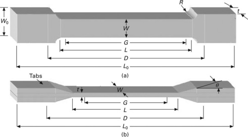
8.1 Typical tensile test specimen geometries. (a) Dog-boned tensile specimen; (b) straight-sided specimen with tapered tabs. Dimensions: W width of narrow section; L length of narrow section; W0 width overall; L0 length overall; G gage length; D distance between grips; t thickness of specimen; θ tab bevel angle; R radius of fillet.
For anisotropic materials, a second test should be performed with specimens fabricated at 90° with respect to the first material direction of material symmetry to obtain the second stiffness value E2. From the measured longitudinal and transverse strains ε1 and ε2, either by means of a biaxial extensometer or with strain gage rosettes, the main Poisson’s ratio v12 can be determined from the negative ratio (ε1− ε2). Also, the longitudinal and transverse tensile strengths, σ1 and σ2 are defined as the ultimate values of stress for the 0° and 90° tensile tests, respectively. The ultimate strains ε1 and ε2 are the strains corresponding to σ1 and σ2.
Tensile test results
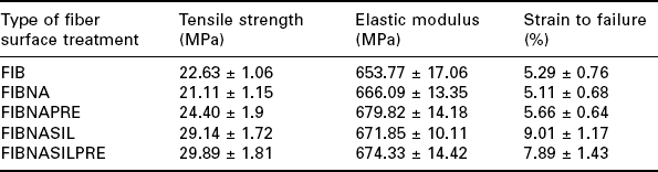
Typical stress–strain curves from the tensile tests for the short fiber henequen–HDPE composite are shown in Fig. 8.2. As expected, there is no noticeable effect on the elastic modulus as a result of the different interface interactions between the HDPE and the henequen fibers (Table 8.1). It is well known that the fiber reinforcing effect is most efficient along the fiber axis orientation. However, the processing technique used to produce the composite, will dictate the final fiber-orientation distribution, which is one of the most important characteristics that determines the effective mechanical properties. The anisotropy expected from an injection-molded part is different from that found in extrusion- or compression-molded parts. Furthermore, the mathematical prediction of the stiffness in a composite stiffness is well established for common fiber orientation distributions, i.e., parallel to the test direction, in a transverse direction to the test direction and when the fibers are randomly oriented.
Table 8.1
Tensile properties of a short fiber henequen–HDPE composite for various different surface treatments
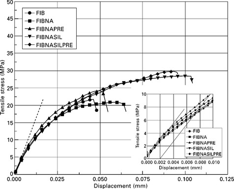
8.2 Representative curves of tensile stress versus strain for henequen–HDPE composites for various fiber surface treatments. Insert shows the slope of line used to calculate the yield stress at ε = 0.2%.
As shown in Fig. 8.2, beyond the linear elastic region, each fiber treatment results in a different composite behavior and, therefore, the fiber–matrix compatibilization has an effect on the strength and elongation of the composite. The type of treatment of the natural fiber, modifies the reinforcing capability of the natural fibers and, consequently, the behavior of the composite in the nonlinear region. At this point, it is convenient to separate the different parameters that govern the tensile strength behavior of the composite. First, shear loading of the matrix is one of the coupling mechanisms that transfers loads between the individual fibers and thus is a general way of distributing the load through the material. For unidirectional composites, the shear behavior is dictated by the resin and in the case of randomly oriented fibers, the fiber–matrix adhesion also comes into play in the load transfer mechanism. For short-fiber reinforced polymers, the existence of stress concentrations at the fiber ends also contributes to the strength of composite, because they are points of possible failure initiation, either by crack propagation along the fiber–matrix interface or through the matrix or failure by matrix and/or interface yielding.
It is known that alkaline treatments result in an improvement in the interfacial bonding by giving rise to additional sites of mechanical interlocking, hence promoting more resin/fiber interpenetration at the interface but with due precaution to avoid fiber degradation. In this instance, this treatment is reflected as a slightly higher elongation capability of FIBNA as compared to FIB. When the fiber surface was modified with an aqueous NaOH solution followed by a resin pre-impregnation process (FIBNAPRE), a marginal improvement of the tensile strength of the composite of approximately 11% with respect to the untreated-fiber composite was observed. In these three cases, the interfacial interactions are mainly physical, i.e., these are frictional and/or weak interfacial physical and chemical interactions. Therefore, any stress concentration at the fiber ends should be withstood by such fiber–matrix interactions. However, when the same alkaline surface modified fiber was treated with a silane coupling agent (FIBNASIL and FIBNASILPRE), a 30% increase in the relative tensile strength and a 100% increase in the elongation capability was observed. This increment in the tensile strength and elongation is attributed to chemical interactions between cellulose fibers–silane coupling agent–HDPE matrix. In this instance, even when the HDPE has been loaded well beyond its yield strength, the covalent bonds between the coupling agent and the polymer resin are more difficult to break and, thus, even when the matrix has yielded and its molecular chains are oriented, matrix failure occurs at high tensile strain. It should be pointed out that the matrix shear yield stress, is below the composite tensile strength which is approximately equal to 7.9 MPa at 0.2% strain.
Stress analysis
From the traditional approach of engineering mechanics of solids used to determine the internal stress on arbitrary inclined sections in axially loaded bars (Fig. 8.3), the state of stress is given by equation [8.2] as follows:
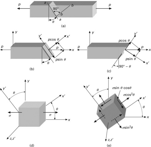
8.3 (a) sectioning of a prismatic bar loaded in uniaxial tension; (b) normal and shear load components on two arbitrary orthogonal planes; (c) shear and normal components of tensile stress of a plane rotated 45°; (d) normal axial stresses acting on the prismatic bar; (e) normal and shear stress components acting on arbitrary orthogonal planes.
where σ is the normal tensile stress applied to the bar. Strictly speaking, upon application of an axial load, on planes which are inclined with respect to the load axis, there are also shear stress components. When θ is equal to zero, σij = σ = P/A and for a non-zero value of θ, there is a shear stress component (σsinθcosθ) whose maximum value occurs in planes located at ± 45°.
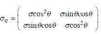
Effect of the interface on the tensile failure mode
Even when an axial tensile load is being applied to the composite sample, it should be remembered that some materials are weaker to shearing loads than to tensile loads. Thus, upon a load increase, yielding may occur along planes where the shear stress attains a maximum value and this type of failure is referred to as ‘a ductile failure’. Failure of the tensile test sample is assumed to occur in a plane transverse to the applied load. However, observation of the failure surfaces and the micro photographs indicates that for an increasing degree of adhesion between fiber and matrix, the failure mode changes from fiber pull-out and ‘brittle like’ failure to a combination of matrix yielding and/or tearing to a shear-type failure as depicted in Fig. 8.3a and 8.3b. Also, for low stiffness materials, yielding of the matrix together with fiber splitting are indicative that the shear stress component is also responsible for failure. As depicted in Fig. 8.3b and 8.3c, the equivalent stress of a tensile stress for a plane rotated 45° with respect to the direction of loading is represented by shear and normal stress components. Shear-induced failure is very strongly influenced by the matrix and then it can be said that shear induced failure is matrix dominated, with some possible contribution from fiber failures by splitting (Fig. 8.4). Then, it can be stated in general that the increase in the tensile strength of the composite is an effect of the fiber–matrix interface. Also, for low fiber–matrix adhesion, the failure mode is dominated by fiber pull-out and matrix failure and for higher fiber–matrix adhesion, the failure mode is more like matrix tearing and flow and fiber tearing. Therefore, the feeble resistance of short fiber composites to stresses, especially those oriented transverse to the fibers is mainly the result of the relatively low strength of the matrix. In this case, for HDPE, with a tensile strength of 25.0 MPa, the effect of the interface strength is seen to have an effect and that an upper bound for the composite tensile strength is imposed by the properties of the matrix. Again, the fiber–matrix interfacial failure modes observed at the micro-mechanical level can be translated to the macro-mechanical behavior of the composite. The role of the covalent bonds formed because of the coupling agent, in particular at high stress and strain values is important considering that the tensile and shear strength properties of the matrix are a limiting value and that the composite is able to withstand larger strains than the physically-modified henequen fiber HDPE composites.
8.3.2 Shear behavior
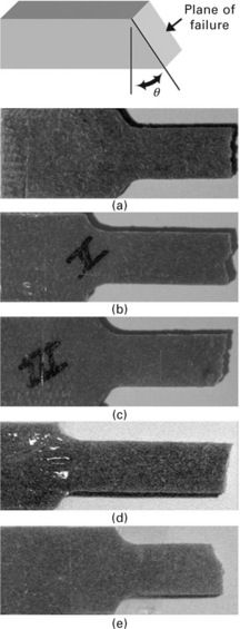
Iosipescu shear testing
In 1967, Iosipescu proposed an in-plane shear testing method for metal with a double-notched beam shape.41 Since then, this method has been widely used to measure the shear stress/shear strain relation of such materials as fiber-reinforced plastics (FRP). The configuration and specimens are shown in Fig. 8.5. This test method is described in ASTM D-5379 standard42 using a Wyoming shear test fixture adapted to a universal testing machine. One of the conditions offered by the Iosipescu shear test has been the uniform shear load in the double notch specimen cross-section. This, in turn, results in a uniform shear stress condition under an in-plane condition. The average shear stress across the notched section of the specimen is calculated using the simple formula:
8.5 Configuration and specimen for the shear test method as described in ASTM D-5379 standard using a Wyoming shear test fixture.
where P is the applied force and A is the cross-sectional area of the specimen between the notches.
Experimental procedures
In this instance, the tests were performed after conditioning the samples at 25 °C. The Iosipescu shear test specimens were cut from the laminates previously obtained, and the dimensions of specimens were 76 mm of length, 19 mm of wide, 2 mm of thickness and the distance between the two 90° notches was 12 mm. The cross-speed used on the universal testing machine (Shimadzu Model AG1) equipped with a 5 kN load cell was 0.5 mm min− 1. The average shear stress across the notched section of the specimen is calculated using equation [8.3].
Stress analysis and failure modes
Fiber reinforced thermoplastic polymer composites have a typical shortcoming: their low shear resistance, especially in planes where the properties are determined by the matrix and the interfacial shear strength. A low shear resistance refers to both low shear modulus and low shear strength. The main difficulty in determining shear properties of a material is to provide a pure shear load in the specimen and thereby assure sufficient precision of the method and the processing of experimental results.
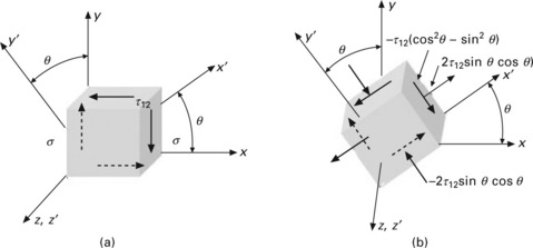
Again, using a simple approach of engineering mechanics, when a body is subjected to pure shear loads, as in the Iosipescu shear specimen, other planes, inclined with respect to the plane of applied load, also contain tensile stresses, as follows:
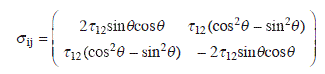
As shown in Fig. 8.6, there is a normal tensile stress component (2τ12sinθcosθ) acting in one plane and a compressive stress (− 2τ12sinθcosθ) at 90° from the first. The shear stress component is equal to τ12(cos2θ − sin2θ) on both planes.
Effect of the interface on the shear failure mode
Typical force–displacement curves from the Iosipescu shear tests for the short fiber henequen-HDPE composites are shown in Fig. 8.7. The shear strength of the HDPE–henequen fiber composites for the various fiber surface treatments is shown in Table 8.2. Similar observations made earlier for the tensile strength on the effect of fiber–matrix adhesion are also evident here. The stress–displacement curves also show a linear–elastic behavior only applicable in a very small range of strain and for larger strains, the stress–strain graph shows a nonlinear elastic behavior. Within a well-defined stress–displacement region, the curves level off markedly towards the displacement.
Table 8.2
Shear properties of a short fiber henequen–HDPE composite for various different surface treatments
| Type of fiber surface treatment | Shear strength (MPa) |
| FIB | 17.17 |
| FIBNA | 18.90 |
| FIBNAPRE | 19.19 |
| FIBNASIL | 19.90 |
| FIBNASILPRE | 20.15 |
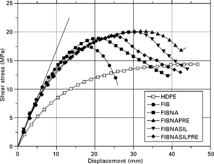
8.7 Representative graphs of shear stress versus cross-head displacement for henequen–HDPE composites for various fiber surface treatments. The graph for neat HDPE is included for comparison with composites.
The nonlinear behavior is noticed in all fiber–surface treatments. This behavior is nonreversible and thus the material is nonlinear viscoelastic. When compared with the pure HDPE resin, the addition of the fibers changes the rigidity of the composite, although it still exhibits the same linear anelastic and the nonlinear viscoelastic behavior. The linear region of the material behavior is observed for stresses close to 7.5 MPa. The fibers with no surface treatment (FIB) show a higher strength than the neat HDPE but the maximum shear stress failure and ductility are considerably reduced. The effect of increasing the fiber–surface area of contact with the matrix seems to improve the shear strength and the ductility of the material. Fiber preimpregnation by itself has no great contribution to the shear strength. The largest increase in shear strength is observed for the fiber treated with both the aqueous alkaline solution and the silane coupling agent. From previous observations of the tensile properties for this fiber surface treatment combination, increments of approximately 20 and 30%, respectively, were obtained. For shear strength, the increase is of the order of 25%.
As mentioned earlier, the inclusion of natural fibers in the polymeric matrix changes the stiffness or rigidity of the material. It is also known that the brittle or ductile character of a material is relevant to the mechanism of failure. Therefore, it is expected that the inclusion of natural fibers in the polymer will result in a decrease of the ductility of the material. However, a clear distinction between a ductile and brittle character or the transition from one to the other is not as simple as might be inferred. The nature of the stress field, testing temperature and the material inhomogeneity itself all play a role in defining the boundary between ductility and brittleness.
As observed in Fig. 8.8a, from the Iosipescu shear test, yielding could occur in the plane joining the two notches. From a finite element model, the shear stress component is not uniform as might be thought from the applied loads (Fig. 8.8b). At the notch roots there is a slightly higher shear stress level than that observed at points located along the center line joining the v-notches of the test specimen. Thus, if yielding is possible, the notch root is a point of possible yield failure initiation. In some instances, a crack was initiated at the notch root, at a point located slightly off the centerline between notches (Fig. 8.8c). This crack was initiated after yielding along the center line between notches and at points located slightly off. Also, according to the finite element model, this point of crack initiation corresponds to a point of maximum normal stress in the sample (Fig. 8.8d). It should be added that the crack starts growing when there is high stress–strain on the specimen.

8.8 Failure modes in Iosipescu test specimens: (a) sample showing yielding along line joining the v-notches; (b) finite element model of Iosipescu shear specimen showing the stress band contours of shear stress, the white area at the center is the possible site of shear failure; (c) sample showing yielding along line joining the v-notches and incipient crack growth on both sides of v-notches; (d) finite element model of Iosipescu shear specimen showing the stress band contours of principal normal stress, the possible site of crack opening is shown.
As for tensile specimens, the interfacial conditions play a very important role in the overall properties of the composites. The physical modifications of the fiber surface contributed to the reinforcing capability of the natural fibers. However, the larger improvement of strength and the elongation capability of the composites were related to the chemical fiber surface treatment. The covalent bonds obtained from the use of a coupling agent result in better mechanical properties of the composites.
8.4 Conclusions
A study of the effect of the fiber–matrix interfacial behavior on the tensile and shear behavior of a model system consisting of HDPE reinforced with henequen fibers (Agave fourcroydes) was performed. Some of the aspects of the mechanical testing program that included loading modes in tension and shear were reviewed and the most important aspects of each test mode were revised. It has become evident that the difficulty in establishing a pure loading mode to obtain a particular answer is enhanced by the geometry of the sample, the complexity of the material’s microstructure, failure modes of both fiber and matrix and most important, the interfacial fiber–matrix conditions.
The mechanics of each test is revised and related to the events observed on each test and on the stiffness and failure modes. Also, the different fiber surface conditions and the ensuing fiber–matrix interface were related to the failure modes. It was observed that the physical modifications of the fiber contributed to the reinforcing capability of the natural fibers. However, the improvement of strength and the elongation capability of the composites were related to the chemical fiber surface treatment. The covalent bonds formed from the use of a coupling agent result in a greater improvement in the mechanical properties of the composites. Therefore, from these test methods it is possible to establish a structure–property relationship between the fiber–matrix adhesion levels and the strength and failure modes for each loading mode.
8.5 References
1. Rowell, R.M., The state of art and future development of bio-based composite science and technology towards the 21st century Indonesia. Proceedings, the fourth Pacific Rim bio-based composites symposium. November 2–5, 1998:1–18.
2. Reddy, N., Yang, Y. Biofibers from agricultural byproducts for industrial applications. Trends in Biotechnology. 2005; 23(1):22–27.
3. Li, X., Tabil, L., Panigrahi, S. Chemical treatments of natural fiber for use in natural fiber-reinforced composite: a review. Journal of Polymers and the Environment. 2007; 15(1):25–33.
4. Samal, R., Bhuyan, L. Chemical modification of lignocellulosic fibers. I. Functionality changes and graft copolymerization of acrylonitrile onto pineapple leaf fibers; their characterization and behavior. Journal of Applied Polymer Science. 1994; 52:1675–1685.
5. Joseph, S., Oommen, Z., Thomas, S. Environmental durability of banana-fiber- reinforced phenol formaldehyde composites. Journal of Applied Polymer Science. 2006; 100(3):2521–2531.
6. Kamel, S. Preparation and properties of composites made from rice straw and poly(vinyl chloride) (PVC). Polymers For Advanced Technologies. 2004; 15(10):612–616.
7. Brahmakumar, M., Pavithran, C., Pillali, R.M. Coconut fiber reinforced polyethylene composites: effect of natural waxy surface layer of the fiber on fiber–matrix interfacial bonding. Composites Science and Technology. 2005; 65:563–569.
8. García-Hernández, E., Licea-Claverie, A., Zizumbo, A., Herrera-Franco, P. Improvement of the interfacial compatibility between sugar cane bagasse fibers and polystyrene for composites. Polymer Composites. 2004; 25(2):134–145.
9. Marsh, G. Next step for automotive materials. Materials Today. (36–43):2003. [April].
10. Valadez-Gonzalez, A., Cervantes-Uc, J.M., Olayo, R., Herrera-Franco, P.J. Effect of fiber surface treatment on the fiber-matrix bond strength of natural fiber reinforced composites. Composites Part B. 1999; 39(3):309–320.
11. Valadez-Gonzalez, A., Cervantes-Uc, J.M., Olayo, R., Herrera-Franco, P.J. Chemical modification of henequen fibers with an organosilane coupling agent. Composites Part B. 1999; 39(3):321–331.
12. Gu, H. Tensile behaviours of the coir fiber and related composites after NaOH treatment. Materials & Design. October 2009; 30(9):3931–3934.
13. Park, J.-M., Quang, S.T., Hwang, B.-S., DeVries, K.L. Interfacial evaluation of modified jute and hemp fibers/polypropylene (PP)–maleic anhydride polypropylene copolymers (PP–MAPP) composites using micromechanical technique and nondestructive acoustic emission. Composites Science and Technology. December 2006; 66(15):2686–2699.
14. Facca, A.G., Kortschot, M.T., Yan, N. Predicting the tensile strength of natural fiber reinforced thermoplastics. Composites Science and Technology. September 2007; 67(11–12):2454–2466.
15. Brahmakumar, M., Pavithran, C., Pillai, R.M. Coconut fiber reinforced polyethylene composites: effect of natural waxy surface layer of the fiber on fiber/matrix interfacial bonding and strength of composites. Composites Science and Technology. March 2005; 65(3–4):563–569.
16. Gomes, A., Matsuo, T., Goda, K., Ohgi, J. Development and effect of alkali treatment on tensile properties of curaua fiber green composites. Composites Part A: Applied Science and Manufacturing. August 2007; 38(8):1811–1820.
17. Bachtiar, D., Sapuan, S.M., Hamdan, M.M. The effect of alkaline treatment on tensile properties of sugar palm fiber reinforced epoxy composites. Materials & Design. 2008; 29(7):1285–1290.
18. Demir, H., Atikler, U., Balköse, D., Tihminlioğlu, F. The effect of fiber surface treatments on the tensile and water sorption properties of polypropylene-luffa fiber composites. Composites Part A: Applied Science and Manufacturing. 2006; 37(3):447–456.
19. Beckermann, G.W., Pickering, K.L. Engineering and evaluation of hemp fiber reinforced polypropylene composites: fiber treatment and matrix modification. Composites Part A: Applied Science and Manufacturing. 2008; 39(6):979–988.
20. Bax, B., Müssig, J. Impact and tensile properties of PLA/Cordenka and PLA/flax composites. Composites Science and Technology. 2008; 68(7–8):1601–1607.
21. Graupner, N., Herrmann, A.S., Müssig, J. Natural and man-made cellulose fiber-reinforced poly(lactic acid) (PLA) composites: an overview about mechanical characteristics and application areas. Composites Part A: Applied Science and Manufacturing. 2009; 40(6–7):810–821.
22. Arbelaiz, A., Fernández, B., Cantero, G., Llano-Ponte, R., Valea, A., Mondragon, I. Mechanical properties of flax fiber/polypropylene composites Influence of fiber/matrix modification and glass fiber hybridization. Composites Part A: Applied Science and Manufacturing. 2005; 36(12):1637–1644.
23. Kim, S.-J., Moon, J.-B., Kim, G.-H., Ha, C.-S. Mechanical properties of polypropylene/natural fiber composites: comparison of wood fiber and cotton fiber. Polymer Testing. 2008; 27(7):801–806.
24. Ochi, S. Mechanical properties of kenaf fibers and kenaf/PLA composites. Mechanics of Materials. 2008; 40(4–5):446–452.
25. Ismail, H., Shuhelmy, S., Edyham, M.R. The effects of a silane coupling agent on curing characteristics and mechanical properties of bamboo fiber filled natural rubber composites. European Polymer Journal. 2002; 38(1):39–47.
26. Abdelmouleh, M., Boufi, S., Belgacem, M.N., Dufresne, A. Short natural-fiber reinforced polyethylene and natural rubber composites: effect of silane coupling agents and fibers loading. Composites Science and Technology. 2007; 67(7–8):1627–1639.
27. Morsyleide, F.R., Chiou, B.-S., Medeiros, E.S., Wood, D.F., Williams, T.G., Mattoso, L.H.C., Orts, W.J., Imam, S.H. Effect of fiber treatments on tensile and thermal properties of starch/ethylene vinyl alcohol copolymers/coir biocomposites. Bioresource Technology. 2009; 100(21):5196–5202.
28. Singleton, A.C.N., Baillie, C.A., Beaumont, P.W.R., Peijs, T. On the mechanical properties, deformation and fracture of a natural fiber/recycled polymer composite. Composites Part B: Engineering. 2003; 34(6):519–526.
29. Ruksakulpiwat, Y., Sridee, J., Suppakarn, N., Sutapun, W. Improvement of impact property of natural fiber–polypropylene composite by using natural rubber and EPDM rubber. Composites Part B: Engineering. 2009; 40(7):619–622.
30. Ragoubi, M., Bienaimé, D., Molina, S., George, B., Merlin, A. Impact of corona treated hemp fibers onto mechanical properties of polypropylene composites made thereof. Industrial Crops and Products. 2010; 31(2):344–349.
31. Ismail, H., Edyham, M.R., Wirjosentono, B. Bamboo fiber filled natural rubber composites: the effects of filler loading and bonding agent. Polymer Testing. 2002; 21(2):139–144.
32. Mulinari, D.R., Voorwald, H.J.C., Cioffi, M.O.H., da Silva, M.L.C.P., da Cruz, T.G., Saron, C. Sugarcane bagasse cellulose/HDPE composites obtained by extrusion. Composites Science and Technology. 2009; 69(2):214–219.
33. Kim, S.W., Oh, S., Lee, K. Variation of mechanical and thermal properties of the thermoplastics reinforced with natural fibers by electron beam processing. Radiation Physics and Chemistry. 2007; 76(11–12):1711–1714.
34. Vilaseca, F., Valadez-Gonzalez, A., Herrera-Franco, P.J., Pèlach, M.A., López, J.P., Mutjé, P. Biocomposites from abaca strands and polypropylene Part I: Evaluation of the tensile properties. Bioresource Technology. 2010; 101(1):387–395.
35. Joseph, K., Thomas, S., Pavithran, C. Effect of chemical treatment on the tensile properties of short sisal fiber–reinforced polyethylene composites. Polymer. 1996; 37(23):5139–5149.
36. Saha, P., Manna, S., Chowdhury, S.R., Sen, R., Roy, D., Adhikari, B. Enhancement of tensile strength of lignocellulosic jute fibers by alkali-steam treatment. Bioresource Technology. 2010; 101(9):3182–3187.
37. Mohanty, A.K., Wibowo, A., Misra, M., Drzal, L.T. Effect of process engineering on the performance of natural fiber reinforced cellulose acetate biocomposites. Composites Part A: Applied Science and Manufacturing. 2004; 35(3):363–370.
38. Threepopnatkul, P., Kaerkitcha, N., Athipongarporn, N. Effect of surface treatment on performance of pineapple leaf fiber–polycarbonate composites. Composites Part B: Engineering. 2009; 40(7):628–632.
39. John, M.J., Anandjiwala, R.D. Chemical modification of flax reinforced polypropylene composites. Composites Part A: Applied Science and Manufacturing. 2009; 40(4):442–448.
40. Sreekumar, P.A., Thomas, S.P., Saiter, J.M., Joseph, K., Unnikrishnan, G., Thomas, S. Effect of fiber surface modification on the mechanical and water absorption characteristics of sisal/polyester composites fabricated by resin transfer molding. Composites Part A: Applied Science and Manufacturing. 2009; 40(11):1777–1784.
41. Iosipescu, N. New accurate procedure for single shear testing of metals. Journal of Materials. 1967; 2(3):537–566.
42. ASTM Standard D5379–05. Standard Test Method for Shear Properties of Composite Materials by the V-Notched Beam Method. In: Annual book of ASTM standards. West Conshohocken: American Society for Testing and Materials; 2000.
43. ASTM Standard D 638-00Standard Test Method for Tensile Properties of Plastics. West Conshohocken: American Society for Testing and Materials, 2001.
44. ASTM Standard D 3039/D 3039M-00. Standard Test Method for Tensile Properties of Polymer Matrix Composite Materials. In: Annual book of ASTM standards. West Conshohocken: American Society for Testing and Materials; 2000.