
Creep and fatigue of natural fibre composites
Abstract:
The growth in applications of natural fibre polymer composites (NFPCs) has increased the importance of understanding time-dependent viscoelastic properties such as creep resistance, stress relaxation, and fatigue, all of which are covered in this chapter. The fundamentals of measurement of these properties are discussed, and the use of short- and long-term prediction of creep resistance of the NFPCs to achieve adequate long-term performance is outlined. The effects of the interfacial interaction between natural fibres and polymers on fatigue and stress relaxation properties of the NFPCs are explored.
11.1 Introduction
The present generation demands technological advancement as well as an environmental awareness for the sustainable development of engineering components. This concern has created an enormous interest in employing natural fibres as reinforcements in polymer composites. The market for natural fibre reinforced polymer composites (NFPC) has experienced tremendous growth in recent years as it is exposed to many different noncritical applications. Natural fibre/plastic composites, which were once relegated to the world of thermosets (phenolics), have now entered the market for products such as flooring, furniture, automotive interior parts, domestic appliances, decking and marine parts.1–4
In 2000, the commercialization of these natural fibre/plastic composites in North America surpassed $150 million. By the end of 2010, however, it will reach nearly $3 billion in sales, with a projected growth rate of 60% per year.5 With this striking growth rate, a comprehensive analysis of the natural fibre/polymer composites market should be considered with regard to the following information:
(a) assessment of the current (2010) and expected future (2020) of the global market;
(b) identification of the key growth segments for these composites, with an emphasis on the ecological and environmental benefits;
(c) identification of the suppliers contributing at all levels to preserve the value chain from fibre suppliers to composite product manufacturers.
A good indication for natural fibre reinforced polymer composites is that the search for the key segments for their growth and exploration is being recognized with full dynamism. They are being increasingly used in structural and other applications, such as construction beams, bolted plates, acoustics materials, hoses, gaskets and mounts. Natural fibres have appealing features such as low density, biodegradability,6 sound mechanical properties and low cost. Short-term and time-independent mechanical properties (strength, modulus, etc.) can be used for a material for a given particular application, but are not enough to determine the effective life cycle of any product. Polymer composites exhibit time-dependent mechanical properties and the changes in stress/strain that occur over time are still observed, even decades later. The increasing number of applications of natural fibre composites have increased the importance of focusing on time-dependent viscoelastic properties, such as creep resistance, stress relaxation.
Creep is the permanent deformation that occurs when a material is under constant stress and is a function of time, temperature and material properties. The term stress relaxation refers to the way in which viscoelastic polymers relieve the stresses under constant strain in a nonlinear, non-Hookean fashion. Creep deformation can go beyond the creep limit, leading to the failure of the component, especially in applications with long-term loading. A proper understanding, measurement, and short and long-term prediction of the creep resistance of the natural fibre reinforced polymer composites (NFPC) component is required in order to design a component for an adequate long-term performance.
11.2 Fundamentals of the creep test
In the creep test, the stress is applied suddenly and is kept constant throughout the test, while the strain is measured as a function of time. The result is generally expressed as a time-dependent compliance. The recovery test generally follows the creep test and centres on the study of how the material relaxes when the material is suddenly unstressed. The stress relaxation test is the opposite of the creep test. In the stress relaxation test, the specimen is strained to a constant elongation and the stress required to maintain the same elongation is measured as a function of time. This result is generally expressed as a time-dependent modulus. A schematic representation is displayed in Fig. 11.1.
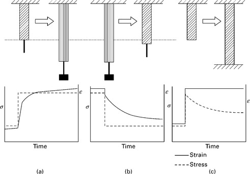
Fig. 11.1 Typical curves displaying the variation of stress and strain with time in (a) creep test, (b) recovery test and (c) stress relaxation test.
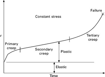
Polymers are viscoelastic, i.e., with the application of a load, stress and strain become functions of time. When a polymer is subjected to a constant load, it deforms elastically (time-independent deformation) as shown in Fig. 11.2. Afterwards, it will continue to deform slowly with time until yielding or rupture causes failure. The creep region is divided into three main regions: primary, secondary, and tertiary. The primary stage is an early stage of loading wherein the creep rate decreases with time. Then it enters the secondary region where the strain rate is constant with time (steady strain creep rate) followed by a rapid increase in the strain rate in the tertiary zone and fracture. The standard test for creep characterization is ASTM D2290.
A general creep recovery graph for a given polymer displays the following regions:
(a) instantaneous time-independent elastic deformation;
(b) linear viscoelastic region (compliance is independent of stress);
(c) equilibrium region/nonlinear viscoelastic region (compliance is dependent on stress);
A creep study in the linear viscoelastic region is generally carried out in order to identify the polymer properties at equilibrium such as modulus (E), viscosity (η), and compliance (D). It is important to distinguish the region in which the viscoelastic properties are linear.
11.2.1 Linear and nonlinear viscoelasticity
For a given constant load σ1, the measurement of time dependent strain ε1 is shown in Fig. 11.3. The specimen is allowed to recover and a greater stress σ2 is applied. The time dependence of the strain ε2 is also shown in Fig. 11.3.
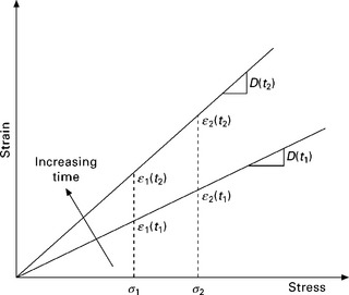
At a given time t1 and t2 after stretching, if ε1 and ε2 are linear with the representing stresses, σ1 and σ2, the stress strain relationship can be given by:
Thus, for any arbitrary time t, the strains at the two stresses can be expressed as:
The strains in the above experiments are proportional to the applied stresses. In general, for a given applied stress σ, creep compliance D(t) is a ratio of strain to stress at a given time t.
This property is described as linear viscoelasticity. In the linear range, the compliance is independent of the stresses employed in the creep test (σ1, σ2 or any other stress values). The strain limits in which a specimen is linear viscoelastic can be ascertained by a simple creep test. A transition from the linear to the nonlinear viscoelastic region is shown in Fig. 11.4.
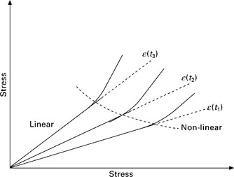
Most polymers usually demonstrate a linear viscoelastic property at low stresses (maximum strain corresponding to ~0.005 or less). At higher stress levels, the material establishes nonlinear viscoelastic behaviour and does not keep the same linear relation between stress and strain. Nunez et al. carried out short term and long-term creep tests on polypropylene/wood flour composites. The creep deformation for strain-time plots was linear up to 10 MPa.7 This signified that the maximum applied stress that works in the linear viscoelastic range is 10 MPa.
11.2.2 Superposition principles
The two superposition principles are significant in anticipating the creep behaviour of plastic materials when they are in the linear viscoelastic range. First, the Boltzmann superposition principle (BSP), depicts the response of a material to various loading histories. The second is the time–temperature-superposition principle, also known as the Williams–Landel–Ferry (WLF) equation, that identifies the equivalence of time and temperature. This will be discussed in the next section.
The Boltzmann superposition principle is applied and limited to the linear viscoelastic region of the polymers.8–10 It states that the response of a polymer to a given loading is independent of the responses to any other loadings already present in it. Thus, each loading step forms an independent contribution to the final strain, so that the cumulative strain is obtained through the addition of all the contributions.
At time τ1 stress σ1 is applied and the strain induced is given by:
According to linear viscoelasticity, the compliance D(t) is independent of stress, i.e. D(t) is the same for all stresses at a particular time. If the stress increment σ2 − σ1 is applied at time τ2 and the strain increases due to the stress increment, σ2 − σ1 is:
Likewise, the strain increase attributed to σ3 − σ2 can be given by:
For creep, the total strain may be expressed by:
where D(t) = 1/E(t) is the compliance, a characteristic of the polymer at a given temperature and initial stress. In other words, the BSP shows that the effect of a compound cause is the sum of the effects of the individual causes.11 Another outcome of the BSP is that the recovery is a mirror image of the preceding creep. i.e. creep and recovery are similar in magnitude.12
11.3 Life prediction of natural fibre composites using long-term creep analysis
As polymers are viscoelastic, polymer composites are hardly used for structural applications, because of concerns over their long-term durability and dimensional stability. Long-term strength, stiffness, and deformation can be obtained by accelerating the testing conditions, such as by creating higher temperature, stress and humidity than the service conditions. An extrapolation of the data can be achieved by employing a prediction model. The precision of the creep anticipation depends on the accuracy of the model–reality correlation and the validity of the model in the extrapolation range of temperature, stress and time. To date, various creep models have been used to predict the service life of polymers and composites, such as mechanical analogs, Findley’s model, Schapery’s model, hereditary integrals, thermal activation theory, time–temperature–stress superposition principle and power law.
The approach of the creep study of natural fibre reinforced plastics is generally carried out in the following steps:
(a) Experimental characterization of creep properties of the composites.
(b) Modelling the measured creep data.
(c) Prediction of the long-term creep behaviour of the composites through short term test measurements.
Experimental analysis emphasizes the parameters and factors affecting the creep behaviour of natural fibre composites.
11.3.1 Factors affecting creep of natural fibre composites
A combination of elastic deformation and viscous flow (i.e. viscoelastic deformation) generally causes creep in polymers. Creep in thermoplastic materials can be ascribed to various material properties, such as crystallinity, molecular orientation13, and environmental and external factors such as applied stress, temperature and humidity.
The creep behaviour of the composite is governed by either the polymer matrix or the reinforcing fibres, depending upon the amount of fibres and fillers and the orientation of the reinforcing fibres within the polymer matrix. For example, the creep deformation of composites which rely upon the reinforcement of long unidirectional fibres is influenced by the creep of the fibres when they are aligned in the direction of loading. On the other hand, it is determined by the matrix creep if the fibres are discontinuous or randomly oriented. The creep mechanism is also greatly affected by the kind of interaction that occurs between the matrix and the fibre. The better the adhesion between the matrix and the fibre, the more effective will be the stress transfer and hence the creep deformation is less.
11.3.2 Effect of filler loading, stress and temperature
Wood fibres are generally preferred to inorganic fibres for noncritical applications because they have certain advantages such as lightweight fibres, ease of processing and high-volume low-cost composite production. A creep study becomes a necessity if the wood fibre reinforced thermoplastics need to be considered for long-term loading applications. Nunez et al. observed the effect of the following variables on the creep behaviour of polypropylene/wood flour composites: filler content (which varied from 0 to 60%), compatibilizing agent polypropylene maleic anhydride copolymer (PPMAN), and temperature.7 Creep deformation reduced with: increasing wood flour content (except at much higher filler concentrations where wetting and filler dispersion problems start), the addition of PPMAN, and low temperatures. They modelled the creep compliance using Burger’s model and the power law equation and ascertained that Burger’s model provides a good description of the linear viscoelastic behaviour of the composite. The effect of the concentration of untreated wood flour on PP composites is displayed in Fig. 11.5. With an increased woodflour content, as expected, deformation decreases owing to the enhanced rigidity of the composites. However 60 wt% woodflour composite is an exception to this as the matrix cannot wet the filler completely rendering the filler-filler interaction weaker and therefore allowing it to be broken easily during deformation.
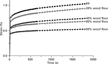
Fig. 11.5 Creep of neat PP and untreated woodflour composites prepared with various filler concentrations at 20 °C. Symbols represent experimental data and continuous lines correspond to the best fit of the Burger’s model with four parameters. Reprinted with permission from Nunez et al.7
Cellulosic fibres, being predominantly polar, easily absorb moisture. Thus, studies have focused more on enhancing the interfacial adhesion between chemically and physically incompatible phases.14 The interfacial adhesion can be modified in several ways:
(a) modifying the thermoplastic matrix by the addition of coupling/adhesion promoting agents;
(b) chemical treatment of natural fibres prior to composite preparation.
A sizing agent, used mainly in the papermaking industry, was indicated to be an appealing method of surface modification for natural fibres.15,16 Researchers have also pointed out that, lignin, a constituent of natural fibres, can be employed as a coupling agent.17,18 Lignin carries polar (hydroxyl) groups, nonpolar hydrocarbon, and benzene rings and can be used to achieve compatibility between natural fibres and the thermoplastic matrix.
The effect of variation in the interfacial interaction between the matrix and the fibre on the creep behaviour of the composite also has been studied (see Fig. 11.6).7 When 5% PPMAN is introduced into the composite system, the deformation is reduced in comparison with untreated composites. With increasing PPMAN content, the extent of creep deformation reduced further owing to the better dispersion of the woodflour and the improved interfacial adhesion. With 10% PPMAN, a reduction of 45% creep deformation compared with neat PP was observed.
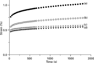
Fig. 11.6 Effect of the interfacial interactions of the creep behaviour of the composites prepared with 40% woodflour: (a) ![]() neat PP, (b)
neat PP, (b) ![]() untreated woodflour, (c) × untreated woodflour and 5% PPMAN, (d) ▼ untreated woodflour and 10% PPMAN. Reprinted with permission from Nunez et al.7
untreated woodflour, (c) × untreated woodflour and 5% PPMAN, (d) ▼ untreated woodflour and 10% PPMAN. Reprinted with permission from Nunez et al.7
As PP is partially crystalline, the crystalline phase hinders the mobility of the amorphous phase. With increasing temperature, the movement of the amorphous part increases, sidelining the reinforcing effect of the crystalline phase, and increasing the extent of creep deformation, as shown in Fig. 11.7. The strains measured at the end of the test, at 50 and 80 oC, are 2.15 and 3.93 times the strain recorded at 20 oC. At 80 oC, the creep curve enters the third zone (Fig. 11.2), where the strain rate increases with time.
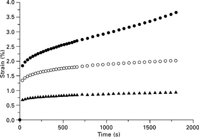
Fig. 11.7 Creep of composites containing 26% of untreated woodflour at various temperatures: ![]() 80 °C,
80 °C, ![]() 50 °C,
50 °C, ![]() 20 °C. Nunez et al.7
20 °C. Nunez et al.7
Wood and thermoplastics are viscoelastic materials and both respond differently to creep behaviour.19–21 The water/moisture uptake of wood–plastics composites is probably the only limiting factor to exploring their applicability in the construction of outdoor facilities. Wood fibre reinforced composites can take up a large amount of water because wood, which consists mainly of cellulose fibres, contains numerous hydroxyl groups that are strongly hydrophilic. The rate of moisture absorption in natural fibre–thermoplastic composites depends on the type of fibre and matrix, temperature, and the variation in water distribution within the composite.22–24
The effect of water absorption on the creep behaviour of wood plastic composites has been studied by Kazemi Najafi et al.25 Employing up to 80% of medium density fibreboard flour as a natural fibre into recycled HDPE, it was observed that the creep strain decreased with increasing lignocellulosic flour, whereas water absorption enhanced the creep deformation of the composite. It was shown that the creep strain increased with immersion time owing to the additive effect of the absorbed water on fibre–matrix debonding, making the relaxation of the molecules easier at a higher moisture content. Bledzki and Faruk conducted a short term flexural creep test to study the creep behaviour of wood fibre PP composites.26 Creep resistance was found to be increased by the addition of an MAH-PP compatibilizer, with decreasing temperature and also with increasing wood fibre content. Pooler and Smith27 have proposed wood plastic composites as an alternative to treated timber for waterfront structures because of their ability to resist water absorption and degradation without chemical treatment. With increasing wood fibre concentration, the moisture content in the composites increases.27 Fibre length and geometry play a significant role in deciding the equilibrium moisture content (volume expansion). Bledzki and Faruk26 have also noted that long wood fibre-reinforced composites are more hygroscopic (nearly twice) than the hardwood composites at higher concentrations of fibre (Fig. 11.8). The use of compatibilizer MAH-PP reduced the hygroscopicity and significantly affected the impact properties. With increasing wood fibre content, the damping index was observed to increase, and this correspondingly lowered the impact strength of the composite. Long wood fibre reinforced PP composites displayed higher impact resistance than their hardwood fibre reinforced counterparts. The compatibilizer MAH-PP improves fibre dispersion in the matrix and facilitates the interfacial adhesion between the phases. It was observed that the MAH-PP treated composites exhibited an enhanced modulus and decreased creep in the composite.
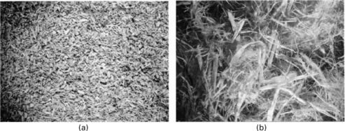
Fig. 11.8 Micrographs of hard wood fibre (a) and long wood fibre (b). Reprinted with permission from Bledzki et al.26
Wood can be used as a substitute filler to reinforce traditional thermoplastics and biopolymers.28–30 However, environmental problems such as deforestation, forest degradation and the impact on global warming and biodiversity has prompted studies on how to utilize other lingo-cellulosic materials in the form of agro residues from annual crops.31 These field crop residues and/or agricultural byproducts, such as cereal straw, rice husk, corn stalk, corn cob, soy stalk and bagasse, are very cheap, voluminous and easily available as raw materials.32 Xu and coworkers investigated the creep behaviour of bagasse/PVC (recycled and virgin) and bagasse/HDPE (recycled and virgin) composites.33,34 Bagasse is a byproduct obtained from sugarcane processing. Acha et al. studied the creep and dynamic mechanical behaviour of bidirectional jute fabric/PP composites.35 The interfacial adhesion between the polar fibres and the nonpolar matrix was improved by two different methods:
(a) Addition of coupling agents, such as MAPP and lignin; and
(b) chemical modification of the fibre surface such as esterification of commercial alkenyl succinic anhydride.
It was observed that the creep deformation decreased with increasing jute content in PP (see Fig. 11.9). The Burger model fitted well to compositions of varying jute concentration in the creep part of the curve. The equation used for theoretical calculations of creep deformation is:
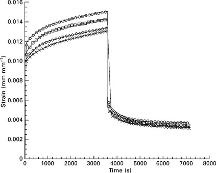
Fig. 11.9 Experimental creep-recovery curves (symbols) and fitting with the four-element model (lines) for PP/jute composites, jute content (wt%): ![]() 9;
9; ![]() 17; ◊ 25; × 30. Reprinted with permission from Acha et al.35
17; ◊ 25; × 30. Reprinted with permission from Acha et al.35
where, σ0 is applied stress, t is time, E0, and η0 are the modulus of the spring and the viscosity of the dashpot for the Maxwell element, respectively, whereas E1 and η1 are the same for Voigt element. A drop in the immediate deformation and the slope of the steady-state creep zone was also observed.
Figure 11.10 displays the creep–recovery graphs for various fibre/matrix treated composites. Surprisingly, the esterified fabrics reinforced and lignin modified PP matrix composites showed the highest creep deformation, whereas both the samples prepared with PPMAN as a compatibilizer displayed the lowest values. Figure 11.11 is the attestation of these results: Fig. 11.11a shows the smoother surface of the esterified fabrics compared with the untreated one (Fig. 11.11c), but even after that the creep deformation is still higher. Figure 11.11c displays no adherence of the PP matrix to the untreated fibres, confirming poor interfacial adhesion between the phases.
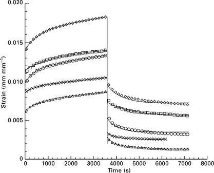
Fig. 11.10 Experimental creep-recovery curves (symbols) and fitting with the four-element model (lines) for composites made from 25 wt% jute: ![]() neat PP with jute;
neat PP with jute; ![]() PP modified with 5 wt% lignin; ◊ esterified jute fabrics and neat PP; × PP modified with 5% Epolene E-43 wax;
PP modified with 5 wt% lignin; ◊ esterified jute fabrics and neat PP; × PP modified with 5% Epolene E-43 wax; ![]() PP modified with Epolene G3003. Reprinted with permission from Acha et al.35
PP modified with Epolene G3003. Reprinted with permission from Acha et al.35
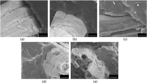
Fig. 11.11 Scanning electron micrographs for composites made from 25 wt% jute: (a) esterified jute fabrics and neat PP; (b) PP modified with 5 wt% lignin; (c) neat PP with jute; (d) PP modified with 5% Epolene E-43 wax; (e) made from PP modified with Epolene G3003. Reprinted with permission from Acha et al.35
on the contrary, it can be seen that the PP has distributed evenly onto the fibre surface (as there is no gap present at the interface) as shown in Fig. 11.11d and 11.11e, which shows the better wettability of the fibres to the matrix. Better interfacial interaction is reflected in the better creep resistance of the composite material.36 It was observed that both the coupling agents G3003 and E-43 wax worked well: G3003 induced better creep performance, possibly because it has a higher molecular mass than E-43 wax, molecular weight (MW) ~ 52,000 and 9,100, respectively. A mass coupling agent with higher MW can form better and tighter entanglements with the PP matrix. Where the coupling agent has a lower MW, the creep deformation is expected to be higher as it acts as a lubricant. Another point to note is that the maleic anhydride content of G3003 is lower than that of E-43 wax. This leads to the conclusion that a higher concentration of maleation is not really required to saturate the fibre surface –OH groups. Acha et al.35 have further analyzed the effect of the amount of the coupling agent applied on the interfacial adhesion and hence on the creep performance of the composite (Fig. 11.10). The creep deformation for 3 and 5 wt% is nearly the same, making it clear that 5 wt% of G3003 coupling agent is sufficient to saturate the fibre surface. However, further increase in the compatibilizing agent (7 and 9 wt% respectively) demonstrated an increase in the creep deformation as shown in Fig. 11.12. The maleated PP is less regular than the virgin PP. With an increasing concentration of maleated PP, the degree of grafting increases, which correspondingly reduces its ability to crystallize.37 In semicrystalline polymers such as PP, creep resistance increases with the increasing percentage of crystallinity,38–40 which effectively reduces with excessive compatibilizing agent. It was expected that the anhydride chains attached to the fibres were either too short or else the polarity of fibres was still much higher than that of the PP matrix. At the same time, the increased smoothness of the fibres reduced mechanical interlocking, causing a reduction in the interfacial strength of the composite. Lignin modified PP composites also showed a higher creep deformation, suggesting that lignin is a poor compatibilizer for the PP–jute system.
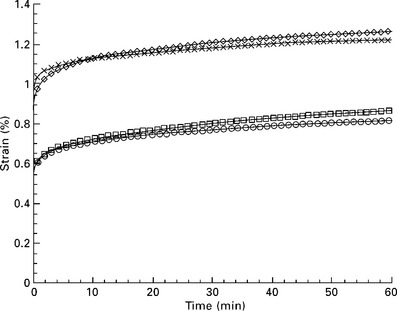
Fig. 11.12 Experimental creep graphs composites for containing 25 wt% of jute and various concentrations of Epolene G3003: ![]() 3%;
3%; ![]() 5%; ◊ 7%; × 9%. Reprinted with permission from Acha et al.35
5%; ◊ 7%; × 9%. Reprinted with permission from Acha et al.35
11.4 Creep modelling
11.4.1 Four-element Burgers model
The easiest way to model the combined viscous and elastic behaviour of a polymer is to employ the mechanical analogs: dashpots (viscous behaviour) and springs (elastic behaviour). The four-element Burgers model is more often used for modelling the creep behaviour of natural fibre reinforced polymer composites.7,35
The various combinations of the spring (elastic deformation) and dashpot (viscous flow) can be correlated with the creep–recovery graph of polymers. The Maxwell model with the spring and dashpot attached in a series, does not work well for creep. It deforms continuously with time as the dashpot responds for loading. The Kelvin–Voigt model with the spring and dashpot in parallel is another simple representation of creep. It displays the time-dependent response of the strain as the viscous flow in the dashpot is opposed by the spring flow. It does not represent instantaneous elastic deformation as well as continued flow under equilibrium. To resolve the problems of the Maxwell and Kelvin–Voigt models, the four-element model developed combines the spring and dashpot in a series and parallel combination as shown in Fig. 11.13. This model exhibited reasonable success in simulating the linear viscoelastic behaviour of polymers. It displays all the regions that are generally observed in real polymers including time-independent elastic deformation, a levelled-off equilibrium region and a recovery region too. For the analysis of the creep–recovery graph, stress and strain curves are generally plotted against time and the data is fitted into the four-element model as shown in Fig. 11.14. It can alternatively be quantitatively analyzed for properties such as modulus, viscosity, irrecoverable creep and retardation time.
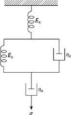
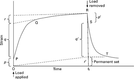
Fig. 11.14 Instantaneous deformation (Maxwell element Ex); PQ linear viscoelastic region (creep Kelvin element); QR equilibrium region (creep Maxwell element), RS instantaneous recovery (Maxwell element Ex), ST delayed recovery (Kelvin element).
One can see that the elastic, viscous, and viscoelastic behaviour of the polymer sample can be easily differentiated. The creep experiment starts when the stress σ0 is applied to the polymer at time t = 0. With the application of stress (σ0), the polymer shows some instantaneous deformation that corresponds to σ0/Ex (OP), where Ex is the independent spring constant of the model as shown in Fig. 11.13. The spring elongates immediately and locks itself after a certain degree of extension. After the time-independent deformation, the separate dashpot (ηx) and the complete Voigt element (Ey and ηy) start responding. At the end, when the stress is relieved completely, the independent spring recoils immediately to the same extent (p = p). The share of the independent dashpot of the total deformation can be correlated with the slope of the strain–time graph when it reaches the equilibrium flow region. The gradient of the line (QR) will be equal to σ0/ηx. Using that gradient, one can determine the permanent set of the sample by extending the time to tf, where the creep test ends. The permanent set in the sample = σ0tf/ηx (r = r′). This independent dashpot does not recover as there is no restraining force acting on it. The permanent set shows the permanent deformation left in the material and that which can be correlated with this independent dashpot. This dashpot represents the molecules slipping past each other. The middle graph corresponding to the linear viscoelastic region (PQ) can be represented by the voigt element of the four-element model. The equations for compliance and strain measurement, respectively, take the form:
where D(t) is the creep compliance.
where ![]() 1;
1; ![]() 2 and
2 and ![]() 3 are the elastic, viscoelastic and viscous behaviour contributions, respectively.
3 are the elastic, viscoelastic and viscous behaviour contributions, respectively.
Wong and Shanks (2008) have quantitatively resolved the creep–recovery behaviour of a natural fibre–biopolymer composite system into elastic deformation, viscoelastic deformation and viscous flow (see Fig. 11.15).41 It was observed that the total creep strain of the unmodified PLA-flax and PHB–flax composite displayed a significant amount of creep. With the use of plasticizers such as tributyl citrate, triethyl citrate and glyceryl triacetate and the interfacial modifier, thiodiphenol, the total creep is effectively reduced in comparison with the unmodified composite system. After quantification of the various deformations, they found that the decrease in the total creep of the modified composites employing either plasticizers or modifiers is accompanied by a decrease in the permanent strain and an increase in the recoverable strain. on the contrary, the addition of a toughening agent, hyperbranched polyester, increased the permanent strain and reduced the recoverable strain, enhancing the overall creep strain of the composites.
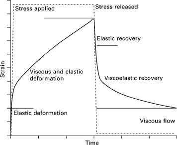
Fig. 11.15 Typical polymer deformation profile showing the elastic, viscoelastic, and viscous flow contributions.
With increasing stress levels from 5 to 15 MPa, it was observed that the total creep strain of the flax–PLLA and flax–PHB unmodified composites increased substantially (Fig. 11.16). Compared with the unmodified system, the use of plasticizers and thiodiphenol reduced the total creep much more. Plasticized composites have the ability to sustain higher loads without suffering a significant increase in the creep strain of the composites.41 The incorporation of toughness modifier, hyperbranched polyester (HBP), increased the creep behaviour. Thiodiphenol was the best additive in terms of reducing the total creep strain, decreasing 83% of the creep with just 5% of it in the composite system. The suppression of the creep was explained by the reduction in the viscous flow contribution of the total creep and the significant increase in the elastic and viscoelastic deformation.
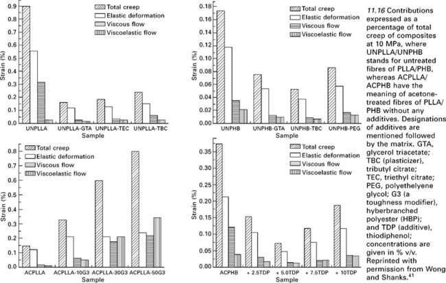
Fig. 11.16 Contributions expressed as a percentage of total creep of composites at 10 MPa, where UNPLLA/UNPHB stands for untreated fibres of PLLA/PHB, whereas ACPLLA/ACPHB have the meaning of acetone-treated fibres of PLLA/PHB without any additives. Designations of additives are mentioned followed by the matrix. GTA, glycerol triacetate; TBC (plasticizer), tributyl citrate; TEC, triethyl citrate; PEG, polyethelyene glycol; G3 (a toughness modifier), hyberbranched polyester (HBP); and TDP (additive), thiodiphenol; concentrations are given in % v/v. Reprinted with permission from Wong and Shanks.41
11.4.2 Time–temperature superposition
The determination of the long-term performance of reinforced composites has often been hindered by the expensive and time-consuming experimentation necessary to obtain reliable results. The time–temperature superposition (TTS) principle, the most useful extrapolation technique applied to almost all types of plastics, was originally developed in the mid-1950s.42,43 In the late 1970s this method was expanded for use with fibre-reinforced composites.4244-45 Time–temperature superposition is based on the assumption that the effect of temperature on the time-dependent behaviour of a material is equivalent to a stretching or shrinking of the real time for temperatures above or below the reference temperature. Thus when plotted on graphs where the abscissa is defined as log time, the individual creep/stress relaxation graphs obtained at different temperatures can be shifted to the left or right to obtain a continuous master graph which spans a much longer time period than was actually employed in testing. The master graph is then used to predict the long-term behaviour of the composites.
Long-term experiments are replaced by short-term tests at higher temperatures. The shifting distance is generally termed the shift factor. The polymers that follow TTS extrapolation are thermorheologically simple and the rest of them are thermorheologically complex. It is evident that the superposition theory is based on the molecular behaviour of polymers and hence uses the term activation energy (Eα) to formulate the equations, such as the Arrhenius equation:46
where, αT is the horizontal shift factor, R is the universal gas constant, T0 is the reference temperature (K), and T is the temperature at which the test is performed (K). Regression analysis is generally carried out employing this equation to evaluate the activation energy for different materials from the experimental data.
One more empirical equation is generally used for TTS: the William–Landel–Ferry (WLF) equation. This equation gives a correlation of temperature with time. For example, if the information at higher temperatures is available, then we can interpolate/extrapolate this data to longer times to correspond with the lower temperature data. The WLF equation takes the following form
where T is the temperature at which the test is carried out. Even though the TTS theory was developed earlier and mainly for amorphous polymers, Neilsen and Landel mentioned that it could also be applied to semicrystalline polymers.47 The changes in the degree of crystallinity with temperature and hence the changes in the modulus of elasticity with temperature in semicrystalline polymers correspond to a part of the vertical shift factor. Neilsen and Landel concluded that the vertical shift factors are mostly empirical with hardly any theoretical validation. Ward argued that the TTS theory cannot be applied to crystalline polymers as their thermal behaviour is rather complex.8 Faucher modified the statements and stated that the theory could be applicable to crystalline polymers provided the polymer structure was maintained in the testing condition, and that it was possible with sufficiently low strain.48
There have been many studies on the applicability of the Arrhenius equation or WLF equation to apply TTS to the creep data.49–53 Pooler et al.27 applied TTS to wood fibre/HDPE composites and emphasized that only a single horizontal shifting is enough to superimpose the creep data. With the use of DMA experiments, storage modulus graphs were only used to ascertain the shift factors, marginalizing other viscoelastic parameters. The TTS theory was also applied by Tajvidi et al.54 to the kenaf fibre/HDPE composite. They observed that the frequency sweep data could be superimposed well with the two-dimensional minimization method to satisfy the TTS requirements. Shift factors conformed to an Arrhenius equation for temperature dependence.
11.4.3 Findley’s power law model
Various researchers have suggested empirical relations to describe the viscoelastic behaviour of fibre-reinforced composites. The Findley power law model is one of the most widely employed analytical models for elaborating the viscoelastic behaviour of fibre-reinforced polymer composites.55 It has the form:
where ![]() o is the instantaneous (elastic) strain,
o is the instantaneous (elastic) strain, ![]() (t) is time dependent creep strain at time t, a is the amplitude of transient creep strain and b is the time exponent.
(t) is time dependent creep strain at time t, a is the amplitude of transient creep strain and b is the time exponent.
The Findley power law model, one of the simple empirical mathematical models, was used to simulate the creep behaviour of reinforced wood–plastic deck boards.56 The power law model formulated by Findley has become a more popular analytical model for describing the viscoelastic behaviour of fibre-reinforced polymer composites under a constant stress. This model has been used in many studies33,57–59 and documented for predicting the time-dependent behaviour of fibre-reinforced polymer composites. The model has also been recommended by the American Society of Civil Engineers (ASCE) Structural plastic design manual for the analysis of fibre reinforced plastic composites (FRPC).60
11.4.4 Two-parameter power law model
In general, creep strain is presented as relative creep (![]() r); a percentage of elastic strain in the material. The equation becomes
r); a percentage of elastic strain in the material. The equation becomes
where A0 is the slope of the power law model. Taking logarithms to both sides to obtain a linear relationship between A0 and n,
The two-parameter power law model is also used for the creep modelling of kenaf fibre/HDPE composites.54
11.4.5 Prediction of long-term creep behaviour of the composites
During the short-term testing of the polymer, we generally do not take physical ageing into consideration owing to the short length of time involved. Compliance makes the value lower than expected, when ageing of the material occurs.61–64 So, it is really important to validate the data obtained from the short term test. Thus, the master graph generated from the short-term creep test may not depict the actual creep behaviour of the composite in the long term. Sometimes, to cross-check the data obtained from the master graph, long-term experiments are also conducted.
Xu et al. employed several creep models (like Findley’s Power Law Model, Burger’s Model, two-parameter power law model) for bagasse/PVC composites.34 All of these models were capable of fitting the creep data but the Burger’s model and two-parameter power law model yielded the most consistent parameters. The time–temperature superposition model predicted the creep behaviour better from the short term tests for PVC composites than from those for the HDPE composites. The three-day creep test (as displayed in Fig. 11.17) for the composites showed a similar trend of the creep curves to those in the 30 min tests (not shown here). It was found that the Burger’s model fitted well for all composites over the entire long-run test. But the parameters for the 30 min test were very different from those for the long-duration creep test. Based on the sum of the squares, Findley’s power law model was also found to fit well over the entire range but the parameters were different and sensitive to different graph shapes and did not maintain consistency. A comparative study was made of creep prediction with the short-term (30 min.) test employing TTS and the long-run experimental results. It was observed that the TTS theory predicted well the creep data for the bagasse/PVC composites and overestimated it in the case of the HDPE composites. This inconsistency in the results for various composites indicated a need for further study and modification of the TTS theory before applying it to natural fibre reinforced polymer composites.
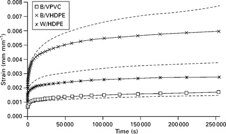
Fig. 11.17 Comparison of TTS predicted creep with experimental data for various composites, where B/V is bagasse/virgin and W is wood. Experimental data are shown as symbols; solid lines are the Burger’s model prediction and dashed lines are predictions from TTS. Reprinted with permission from Xu et al.34
11.5 Nonlinear viscoelastic response
Many polymers display linear viscoelastic behaviour for small deformations or stresses. The theory of linear viscoelasticity generates a simple mathematical correlation of stress–strain–time parameters. The stress or strain where the deformation behaviour is estimated as linear, however, is small enough compared with the total stress or strain before yielding or fracture. Furthermore, at high temperatures, one can observe the nonlinear deformation even at low strains (less than 0.2%). Therefore, theories adopting linear viscoelastic behaviour do not provide a generalized solution for the wide range of time, loading conditions and temperatures. For example, solid lumber was originally mostly used as a material for naval waterfront facilities.65 However, lumber degrades over time and, therefore, requires chemical treatment to effectively delay the course of degradation. This apparently increased expenditure on the repair and replacement of these structures. In addition to that, the lowering of the water quality owing to the leaching of the chemically treated lumber is a worrying environmental factor. An alternative for this is to use a material that can withstand the static as well as time-dependent loading during its service period (i.e. the material must have high fatigue and creep resistance).
The following approaches are generally used to address nonlinear viscoelasticity. The first approach generally uses continuum mechanics to derive the constitutive equations for nonlinear viscoelasticity. The second approach uses thermodynamics theory for irreversible processes. Rangaraj et al.65 extruded wood flour with high density polyethylene (HDPE) and carried out a series of creep and recovery tests. After crossing a threshold value of creep stress amplitude and duration, it was observed that there is a permanent deformation along with a reduction in stiffness (i.e. damage) in the material. The damage and permanent strains were found to depend on creep stress amplitude and duration. To correlate the damage and permanent deformation effects, they developed a nonlinearly viscoelastic model and equated the results favourably with the experimental creep/recovery data.
Pramanick et al.66 worked on developing a model to study the nonlinear behaviour of creep in polymer composites of the two-phase system where they used an extended ‘theory of mixtures’ to describe the creep phenomenon. It is interesting to mention that the effect of temperature and stress on the creep deformation of the individual constituents can be fitted in combination in a single analytical function where the interaction is additive. They approximated stress and temperature related shift factors in terms of the activation energy of the constituent phase. As the temperature shift interferes with the stress shift, they incorporated a relationship between these shifts in the model to make the stress equivalency of temperature possible. Rice husk–HDPE composites were experimentally analyzed with this model, which was validated in the linear as well as the nonlinear viscoelastic regions of creep for rice husk–HDPE composites with power-law-Boltzmann’s superposition principles.67 It was suggested that the model could also incorporate environmental variations such as relative humidity, time, stress and temperature. Lin et al.68 carried out the creep and recovery testing in the flexural bending mode for 60% wood flour reinforced extruded HDPE composites to determine the creep related material constants for the nonlinear viscoelastic model.
11.6 Stress relaxation
George et al.69 investigated the stress relaxation behaviour of short pineapple-fibre reinforced polyethylene composites. The stress relaxation of the composite decreased with the incorporation of stiff natural fibres in the polymer matrix. The fibre–matrix bonding at the interface also plays a significant role in the overall performance. Various surface modification techniques were developed to enhance the interfacial adhesion and hence decrease the relaxation of stress.70 George et al. observed that the stress relaxation surprisingly increased with the increasing length of the fibre.70 They reasoned that with increasing fibre length, the possibility of the bendingIcurling of fibres as well as of greater fibre–fibre interaction would be higher, which would cause stress to be transferred insufficiently. An optimum balance of fibre length is a crucial parameter as it may lower the relaxation modulus owing to insufficient stress transfer or else because of the pullout of fibre from the matrix when deformed.71 Mechanical and viscoelastic properties decrease after exposure to water depending on the time of water immersion, fibre loading and fibre surface modification.72 Fibre orientation and strain level create an impact on the stress relaxation behaviour of the composite.69,73
One can obtain a relaxation master graph the same way as for a creep graph, spanning a much longer period of time. With log (time) as the abscissa, the individual relaxation graphs obtained at various elevated temperatures and/or strain can be shifted to generate a continuous master graph. To achieve a master graph for both time and stress superposition, vertical shifts can also be applied in concurrence with horizontal shift. Therefore, a process can be formulated where a series of short-term relaxation tests are performed at elevated temperatures/strains leading to the generation of a family of graphs for an established composite system. This technique was used successfully to anticipate the stress relaxation behaviour of polymer composites in the long-term utilizing horizontal and vertical shift in the graph concurrently.74,75 TTS has taken advantage of the relationship between temperature and viscoelastic behaviour in fibre-reinforced composites.42,44 Findley’s power law model has also been used successfully by many researchers to model short as well as long-term relaxation behaviour.76
The increasing applications of short-fibre composites for static as well as dynamic loadings, for instance, hoses, V belts, tubes and cables, has increased the importance of stress relaxation measurements, particularly for rubber based composites. The interface interaction between the rubber and the filler can be observed through the stress relaxation measurements. Cured elastomers undergo a marked relaxation when stretched at a given deformation.77 Stress in the deformed component relaxes in proportion to a logarithm of the period. Bhagawan et al.78 detected a two-stage relaxation pattern for the short jute fibre–nitrile rubber composites. Flink and Stenberg79 mentioned that the slope of the stress relaxation graph provides a better way to study the interfacial adhesion between the phases while carrying out a study on short cellulose fibre–natural rubber composites. A plot of E(t)/E(t = 0) against log(t), where E(t) is the stress at a given time and E(t = 0) is the initial stress, reveals the interfacial interaction.
Kutty and Nando80 studied the stress relaxation behaviour of short fibre-thermoplastic elastomer composites and the effect of fibre loading, orientation, strain level, strain rate and temperature. A two-stage relaxation process for unfilled thermoplastic polyurethane and a three-stage relaxation process for the short kevlar fibre reinforced polyurethane composites were reported. The orientation of fibres in the polymer matrix can be either longitudinal or transverse as shown in Fig. 11.18. With variation in the fibre loading, it was observed that the initial rate of relaxation in the transverse direction (except at 40 phr) is nearly 100% more in the longitudinal direction (see Fig. 11.19). Even the second and the third slopes are higher in the transverse direction. One can also see the consequences of fibre loading on the stress relaxation phenomenon which reveals that it has similar effects on both orientations of the fibres. It is observed that the initial rate of relaxation is dramatically reduced to 34% with the incorporation of only 10 wt% fibres (see Fig. 11.19). With a further increase in the fibre content, the rate of decrement was not significant.
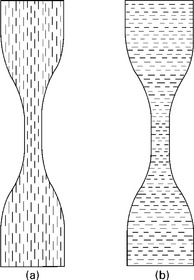
Fig. 11.18 Schematic representation of orientation of fibres in relaxation test specimen: (a) longitudinal orientation, (b) transverse orientation. Reprinted with permission from Kutty and Nando.80
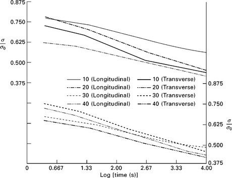
Fig. 11.19 Effect of fibre orientation and fibre loading on stress relaxation of Kevlar fibre reinforced polyurethane composites. Reprinted with permission from Kutty and Nando.80
Figure 11.20 displays the effect of various strain levels on the stress relaxation plot of neat thermoplastic polyurethane (at a constant strain rate of 0.16 s− 1). Two different slopes of the plot at any given strain level shows that there are two different relaxation mechanisms operating in a system. The first mechanism is for shorter period (~ 200 s). The change in the slope suggests the point of time at which the changeover in the mechanism occurs. For the first relaxation mechanism, the rate of relaxation is independent of the strain levels up to 100% as it is also observed81 in many vulcanized rubbers such as natural rubber (NR), styrene–butadiene rubber (SBR), and isoprene rubber (IR).82 But at 500% strain, the relaxation rate is increased by ~ 65% which is accredited to the build-up of the crystalline phase as occurs in natural rubber.82 The increase in the second slope and the shift in the changeover point to shorter times at higher strains indicates that the first relaxation mechanism takes over at a faster rate at higher strain levels.
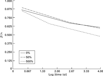
Fig. 11.20 Effect of strain level on the stress relaxation of neat thermoplastic polyurethane (strain rate, 0.16 s− 1). Reprinted with permission from Kutty and Nando.80
Varghese et al.83 carried out the stress relaxation study on untreated and acetylated short sisal fibre reinforced natural rubber composites and reported that the acetylation improves adhesion between the fibre and the matrix. The rate of stress relaxation might be a better way to rank the adhesion of the fibres/fillers with the matrix. They further investigated the effect of strain level, fibre loading, fibre orientation, and temperature on the stress relaxation behaviour of the same chemically treated composite. Ageing is also one of the parameters that changes the stress relaxation behaviour of the polymer composites (see Fig. 11.21). Varghese et al.84 aged the NR–sisal fibre composite specimens at 0 and 100 °C for 4 days and then tested them. It was noted that the composites employing no bonding agent (Mix D) as well as with bonding agent (Mix C) showed a decreased rate of initial relaxation with ageing. The relaxation graph for the composites with bonding agent demonstrates the maximum crossover time and contribution to the initial relaxation. In the second slope of the curve, the relaxation rate increases sharply owing to chain/crosslink scission.
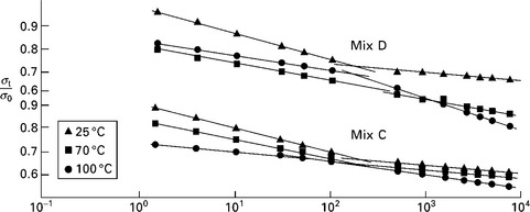
Fig. 11.21 Stress relaxation graphs of mixes C and D at 30% elongation (after ageing). The composition of mix C is: natural rubber 100 phr, acetylated sisal fibre 15 phr, resorcinol 3.75 phr, hexamethylenetetramine 2.4 phr, zinc oxide 5 phr, stearic acid 1.5 phr, and sulfur 2.5 phr. Mix D does not contain resorcinol or hexaethylenetetramine but the remaining ingredients are the same. Reprinted with permission from Varghese et al.83
11.7 Fatigue
The other mechanism that exhibits a form of property deterioration during the service life of fibre reinforced composites is ‘fatigue’. Fatigue failure in unidirectionally oriented fibre reinforced composites takes place throughout the volume of the material and not in a localized fashion. Phenomena such as debonding at the interface, fibre breakage, matrix cracking, delamination and transverse ply cracking occur either interactively or independently depending on the manufacturing method adopted. The predominance of a particular phenomenon over others depends on the material variables and testing conditions involved. In general, matrix cracking and delamination occurs early, whereas fibre–matrix debonding and fibre fracture starts during the beginning of component life but accumulates rapidly towards the end, leading to the final failure.85 In comparison with metals, composite materials display greater variation in terms of their fatigue properties because of the greater number of variables involved. Unfortunately, most of the research involved has focused on synthetic fibre/resin composites.86–93 The study of natural fibre reinforced composites, and their ability to withstand complex forces, and material, as well as external variables, with a view to employing them in structural applications is timely but there are few reported studies.
The main constituent of natural fibres is cellulose.94 The basic unit of cellulose, anhydro-D-glucose, contains three hydroxyl (− OH) groups. These hydroxyls form inter/intramolecular hydrogen bonds and also bond with the hydroxyl groups from damp air and become hydrophilic. The moisture content of the natural fibres varies between 3 and 13%.95 A problem with natural fibres is that there are more variables that determine their final properties and performance. The physical and mechanical properties of natural fibres are governed by factors such as the fibre diameter, the structure of the fibre, whether the fibres are collected from the stem, leaf or seed and the growing conditions of the plant.96 The structure of the fibre itself has many variables, including the amount of crystalline fibrils, the spiral angle, supramolecular structure (degree of crystallinity), degree of polymerization, type of cellulose, defects, orientation of the chains of noncrystalline cellulose and crystalline fibrils, pore size and pore volume, decide the final structure and hence the properties of the fibres.94,97,98 The conclusion is that the static properties of natural fibre reinforced composites display a great variation in their results because of the dimensional variations and hydrophilicity of the fibres and hence the fluctuation in fatigue properties is expected to be much higher than that in synthetic fibre–resin composites.
The incorporation of hydrophilic natural fibres in traditional thermoplastics weakens the interfacial bonding between them with time leading to the deterioration of the mechanical properties (ageing phenomenon). Waxy residues on the fibre surfaces also introduce poor bonding characteristics to these fibres.99 The effects of this time-dependent declination of the mechanical properties owing to the weakening of the interfacial bonding is an important area of study for applications that require the composites to withstand long-term exposure of the composites. Alternative options for enhancing the mechanical properties of natural fibre reinforced polymer composites were focused on: the use of effective coupling agents to increase the hydrophobicity of the natural fibres, hybridization of natural fibres with more environmental ageing resistant synthetic fibres such as carbon and glass fibres.
To enhance the interface interaction between the fibre and the matrix and hence to improve the properties of the composites, natural fibres are either physically or chemically treated. The physical methods such as thermal treatment,100 calendaring,101,102 stretching,103 and hybrid yarn production104,105 involve only the surface modification and do not alter the chemical composition of the composite. Chemical treatment of the fibres mostly uses a coupling agent that generally reacts with the fibre as well as with the polymer. Coupling agents form chemical bonds (either covalent or hydrogen bonding) and improve the adhesion at the interface. In general, the natural fibres are treated with compounds containing isocyanates,106,107 methyl,105,108,109 and organosilane groups.110 Graft copolymerization is the other regular method used for natural fibre reinforced polymer composites. The alkalization of fibres with NaOH solution111,112 has resulted in a substantial improvement in the strength of the composites.
11.8 Factors affecting the fatigue life of natural fibre composites
11.8.1 Internal/material variables
In general, the fatigue properties of composites depend on the polymer type (brittle or soft matrix)/structure, MW, crosslinking, type of filler, and its content. For polymer composites with a brittle matrix such as epoxy, it is the interfacial strength parameter that plays an important role in the fatigue behaviour of composites. The interfacial strength controls the crack propagation (crack bridging, debonding) phenomenon. With poor interfacial bonding between the phases, debonding and fictional sliding occur readily upon crack extension, allowing the long fibres to remain intact and bridge the crack. Contrarily, a stronger interface suppresses sliding and contributes to fibre fracture instead of bridging the crack.113,114 Microcracking in toughened epoxy/polyester as well as in thermoplastic matrices is also a dominant energy dissipation mechanism precluding plastic deformation (which readily occurs in bulk matrix).116
Effect of filler, whether treated or untreated, and content
Gassan investigated the effect of the fibre and the interface parameters affecting the tension–tension fatigue behaviour of various natural fibre reinforced plastics.117 He selected the combinations of fibres (jute and flax in yarns and woven form) and matrix (epoxy resin, polyester resin, and polypropylene) so as to study the individual effects of fibre type, textile architecture, interphase properties, fibre properties and their content on the fatigue behaviour of natural fibre composites. A variation in the damping of composites was correlated with the individual effect of these parameters against an increasing applied load. It was concluded that natural fibre reinforced plastics employing higher fibre strength and modulus, firmer interfacial adhesion between the phases or higher amounts of fibre in the matrix demonstrated higher critical loads for damage initiation as well as higher failure loads. He also observed the reduction in damage propagation with the above effects.
Figure 11.22 depicts the effect of the type of the natural fibre incorporated in a given polymer matrix. One can see that the specific damping capacity (energy loss/strain energy) increases significantly suggesting that the start of the damage initiation is at 45 N mm− 2 for the jute–epoxy composite. With further increase in the mean stress (keeping the stress ratio R and frequency constant), specific damping capacity increases owing to damage propagation and the composite finally fractures at 120 N mm− 2. A similar type of behaviour is observed in flax–epoxy composites with much higher specific damping capacity values. The cellulose content in jute and flax fibres was reported to be 61.4 and 78.5 wt.%, respectively.118 The energy required for fibre damage is far more than expected. This suggests that the greater part of the energy is lost in the internal friction owing to the viscoelastic deformation of the fibre itself. It is also reported that the damage of the fatigued fibres mainly results from micromechanical degradation followed by the structural breakdown of the microfibrils.119
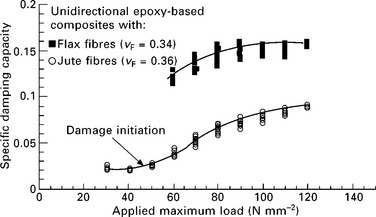
Fig. 11.22 Specific damping capacity versus applied maximum load for unidirectional flax and jute epoxy composites (104 load cycles/load level). Reprinted with permission from Gassan.117
Gassan117 proposed that the cellulose microfibrils transfer the stress from one layer to the other layer and decrease the role of the cementing matrix (hemicellulose and lignin) as a load carrying component (similarly to the laminate composite fibres). It is the cellulose microfibrils that mainly determine the delamination crack growth resistance.
Figure 11.23 reveals the effect of the natural fibre architecture on the fatigue mechanism of the composites. With woven fibres in the brittle epoxy matrix, the rapid damage development during the initial loading cycles is mainly accredited to the matrix cracking along the off-axis plies and perpendicular to the loading direction. These microcracks coalesce with time and grow along the interfaces and delaminate (if present). Finally, the composite fails with the fracture of the fibres.120 In contrast to this, interfacial debonding is the dominant mechanism of composite failure in unidirectional composites.121 Crack propagation in [0,90] composites primarily depends upon the interfacial interaction between the matrix and the fibre. With a relatively weaker interface, debonding and frictional sliding occurs. A strong interface between the phases suppresses the interface sliding and contributes to fibre fracture114,115,122,123 increasing the critical stress for damage propagation.
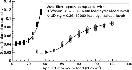
Fig. 11.23 Specific damping capacity versus applied maximum load for woven and unidirectional (UD) reinforced jute-epoxy composites. Reprinted with permission from Gassan.117
In natural fibre reinforced polymer composites, the interaction between the fibres and the matrix was improved by the use of coupling agents.124–126 the use of MAH-PP copolymer as a coupling agent in jute–PP composites demonstrated reduced damage propagation with increased critical loadings.
Effect of physical/chemical modification of fibre/matrix on fatigue mechanism
A fatigue phenomenon is more common with decreasing fibre modulus in unidirectional composites.127,128 Shrinkage of fibres during alkali treatment has a significant impact on the fibre structure and hence on the mechanical properties of the fibres and consequently on the composites.129 Alkali (NaOH) treated flax fibres having various states of allowed shrinkage showed tremendous variation in their yarn tensile modulus (changes from 1.5 to 0.2 times compared with their untreated counterpart when the shrinkage varied from 0 to 26%).117 Alkaline treatment alters the Hermans orientation factor (0.96 for zero-shrunk fibres and 0.653 for 26% shrunk fibres). Gassan et al.129 highlighted the effect of fibre shrinkage on the fatigue properties of flax–epoxy unidirectional composites (Fig. 11.24). They observed a higher specific damping capacity at a given loading for increasing shrinkage of the fibres. Impact stiffness also increases with decreasing shrinkage. With decreasing shrinkage, i.e. increasing orientation of the fibrils, it was observed that the damage initiation in composites was 40–50% higher than in the composites with shrunk fibre.129 In other words, the stress required to initiate the damage in a composite system was reduced with increasing shrinkage. The lowered stress for matrix cracking can be ascribed to the decreased fibre modulus and increased fibre diameter owing to shrinkage as mentioned in the following equation.130
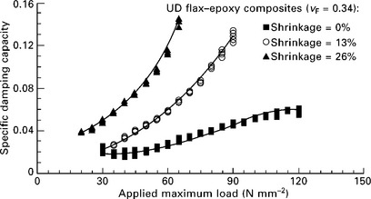
Fig. 11.24 Specific damping capacity versus applied maximum load for UD epoxy composites which contain flax fibres of various fibre tensile strength and modulus (104 load cycles/load level). Reprinted with permission from Gassan.117
where σc is the stress required to initiate the crack (in the matrix), f is the fibre volume fraction, τ is the interfacial shear stress, Ec is the modulus of the composite system, ![]() m is the fracture energy for the matrix and Em is the modulus of the matrix.
m is the fracture energy for the matrix and Em is the modulus of the matrix.
It was observed that the noncellulosic components (hemicelluloses and lignin) of the natural fibres can be removed by alkali treatment.130,131 With the removal of hemicellulose, the empty space between the fibrils helps them to rearrange themselves in the direction of loading. This fibril rearrangement increases the load sharing capability and hence the tensile/flexural strength of the composite. Some studies reported an increase in % crystallinity of the fibres through alkali treatment.132–135 The fibres treated with NaOH decrease the spiral angle and increase the randomness of molecular orientation, which increases the modulus of the fibre.
Gassan and Bledzki124 modified jute fibre with alkali, MAH-PP and silane, and found that surface modification had obvious effects on the fatigue behaviour of jute fibre reinforced polypropylene composites.124,136,137 To investigate the influence of MAH-PP content on the fatigue behaviour (correlated with specific damping, dynamic modulus, hysteresis, and accumulated dissipated energy) of jute–PP composites, Gassan and Bledzki carried out testing in InDyMat (intelligent dynamic mechanical testing). With improved fibre–matrix adhesion, damage resistance was increased to higher maximal stresses and the progress (rate) of damage was also reduced.137
Figure 11.25 clearly shows that it is the fibre–matrix adhesion that reduces the progress of the damage with increasing fibre content. Untreated jute–PP composites hardly display any change in accumulated dissipated energy whereas the MAH-PP coupling agent improved the stress transfer and hence the increase in dynamic strength.
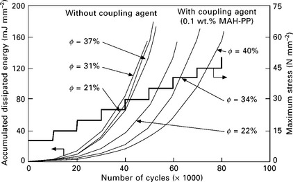
Fig. 11.25 Influence of fibre content on the specific damping capacity of MAH-PP modified jute-PP composites, test frequency 10 Hz, R 0.1, 104 cycles/stress level, φ fibre content (vol%). Reprinted with permission from Gassan and Bledzki.137
For a similar volume fraction of fibre, one can see ~ 40% increment in the dynamic strength with 0.1 wt.% of coupling agent in jute–PP composites (Fig. 11.26). Furthermore, the damage in both unmodified and modified composites is not abrupt but increases continuously with stress.
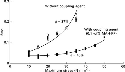
Fig. 11.26 Influence of surface treatment on the specific damping capacity (SDC) of jute-PP composites, test frequency 10 Hz, R 0.1, 104 cycles/stress level, ϕ fibre content (vol%). Reprinted with permission from Gassan and Bledzki.137
Ray et al. carried out an impact fatigue study on 35% jute–vinyl ester composites on untreated and alkali-treated fibres.138 A longer time for alkali treatment is expected to improve the crystallinity and remove the hemicellulose. It was observed that a 4 h alkali treatment of jute fibres imparted optimized interfacial bonding and fibre strength properties. Figure 11.27 displays clearly that the alkali-treated fibre-reinforced composites show a marked drop in load after the fracture of matrix and fibres. Contrarily, untreated fibres showed just the pullout of the fibres. It was observed that with an 8 h fibre treatment, even though the fibres had superior characteristics, the tensile/flexural strength of composites reinforced with these fibres was lower. With increased treatment time, fibrillation occurs to a great extent and renders the reduced fibre diameter less effective in the property enhancement of composites.
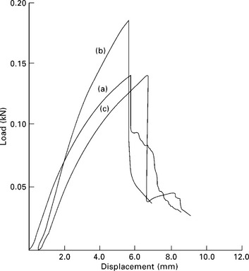
Fig. 11.27 Load–displacement graph of 35 vol% composites reinforced with jute fibres: (a) untreated, (b) 4-h alkali treated, (c) 8-h alkali treated. Reprinted with permission from Ray et al.139
11.8.2 External variables
External variables include the effects of stress amplitude, stress intensity factor, mean stress, temperature, frequency and environment. A systematic study of these variables on the fatigue mechanism of natural fibre reinforced polymer composites is needed to exploit these composites in wide-ranging external surroundings. Some work related to S–N plots and constant life line graphs provide some basic information regarding the effect of these variables on the fatigue behaviour of composites.
S–N graph
Ray et al.139 have plotted (Fig. 11.28) E–N type fatigue graphs for alkali-treated and untreated jute fibre reinforced composites, which show a four-region fatigue graph for untreated and a three-zone graph for alkali-treated jute-reinforced vinyl ester composites. It is clear that the E-N graph decreases progressively with applied impact energy which indicates that the alkali-treated composites have longer endurances. This is not observed in untreated fibre reinforced composites. For 4-h alkali-treated fibres, the slope in region II is more rapid than in 8-h alkali-treated fibres. This reveals that the damage mechanisms (debonding at the interface, matrix cracking and fibre fracture) are rapid. Nevertheless, it was observed that 8-h alkali-treated fibres displayed improved impact fatigue properties.
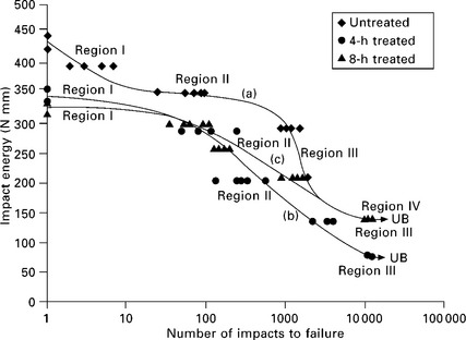
Fig. 11.28 Impact fatigue graph of 35 vol% composites reinforced with: (a) untreated jute fibres, (b) 4-h alkali-treated jute fibres, (c) 8-h alkali-treated jute fibres. Reprinted with permission from Ray et al.139
Constant life line graphs
In most of the preliminary analyses of the fatigue behaviour of natural fibre composites, results were demonstrated in terms of variation in specific damping capacity117 and limited S–N (stress versus number of cycles to failure) data.140 Bond and Ansell plotted constant life diagrams for carbon fibre/epoxy composites and identified that they followed a parabolic graph shifted towards the tension side of the plot.141 The shift of the graph was attributed to the relative weakness of the fibre composites under cyclic and compressive static loading. Constant-life lines are capable of predicting the fatigue lives of composites at any R ratio141,142 and these are a valuable tool for design engineers to apply to components failing owing to fatigue (Fig. 11.29). The area under this constant-life line (a plot of mean stress (x axis) against alternating stress (y axis) makes up safe combinations of mean and alternating stresses.
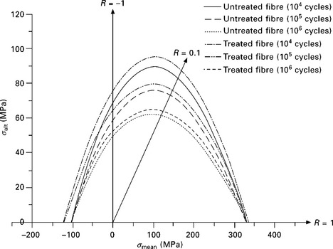
Fig. 11.29 Constant life diagrams for untreated and treated sisal fibre epoxy matrix composites for 104, 105, and 106 cycles. Reprinted with permission from Towo and Ansell.144
While analyzing the fatigue behaviour of sisal fibre reinforced thermosetting (polyester or epoxy) composites comprising untreated or alkali treated sisal fibres, Towo and Ansell143 used S–N curves and dynamic mechanical thermal analysis (DMTA) to investigate variations in the mechanical properties of these composites with the number of fatigue cycles and temperature. Interfacial damage was greater in the composites reinforced with untreated sisal fibres. Better interfacial bonding brought about by the alkali treatment improved the fatigue life of the composites. For the same composite system, Towo and Ansell built constant-life lines from S–N graphs using experimental results.144 At different stress ratios R (ratio of minimum to maximum cyclic stress), the fatigue failure in tension–tension (stress ratio R = 0.1) mode and reversed loading (R = − 1; i.e. tension–compression) were assessed. The scatter in the number of cycles to failure for the specimen tested under tension–tension loading showed that the natural fibre reinforced composites have highly fluctuating mechanical properties and hence fatigue lives. However synthetic fibre composites also demonstrate variation in their fatigue lives. In spite of this, for alkali-treated sisal fibre reinforced polyester (there was hardly any improvement in epoxy composites possibly owing to similar interfacial bond strengths) composites, an improvement in terms of load carrying capacity and an increased rate of fatigue degradation during cyclic loading was observed. It was reasoned that this was due to brittle micro-failure events occurring in the composites. Alkali-treated composites displayed superiority at lower fatigue lives (up to 106 cycles).
Hysteresis loops
Bond and Ansell141 even studied the hysteresis loops at these R ratios (ratio of minimum to maximum cyclic stress). Hysteresis loops are generally used to measure properties such as loss of stiffness and internal friction during fatigue.145 These graphs also show fatigue damage development and the nature of the chemical bond between fibre and matrix. Towo and Ansell144 used hysteresis loop graphs to distinguish the differences in damage development between composites reinforced with untreated sisal fibres and those containing alkali-treated fibres as shown in Fig. 11.30.
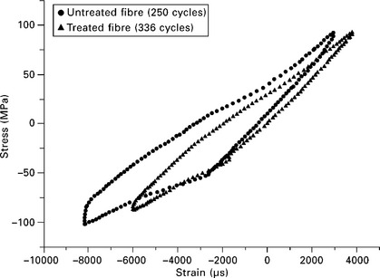
Fig. 11.30 Final hysteresis loops for untreated and 0.06 M NaOH treated composite at R = − 1 (fully reversed loading). Reprinted with permission from Towo and Ansell.144
Composites endure heavy interfacial damage during tension–compression loading (R = − 1) with an increasing number of cycles. Hysteresis experiments display smaller loops during the initial cycles. With an increasing number of cycles, the loop area just before failure was increased by ~ 447% and 258% for untreated and alkali-treated fibre composites, respectively. Unidirectional fibre composites are weak when under compressive loading and suffer debonding and fibre buckling leading to the formation of kink zones at failure (see Fig. 11.31). In short, the smaller the loop area, the lesser is the energy dissipation and correspondingly the better is the bonding between the fibres and the matrix.
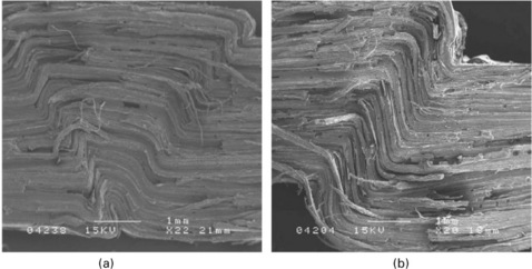
Fig. 11.31 Failure of sectioned sisal fibre epoxy resin composite in tension–compression loading showing (a) wedge-shaped kink failure and (b) single kink failure (R = − 1). Reprinted with permission from Towo and Ansell.144
Effect of low-velocity impact
Tong and Isaac carried out various experiments to determine the effects of low-velocity impact on the residual tensile and fatigue properties of nonwoven hemp fibre mat reinforced polyester samples and compared them with ± 45° glass fibre reinforced polyester samples (Fig. 11.32).146 The damage accumulation of the composites was correlated with the degradation of the tensile modulus during fatigue cycling. The following were the noticeable points observed: (a) the necessity of a relatively high pressure on the hemp fibre reinforced composite during curing in order to ascertain a higher volume fraction of the fibre to render the reinforcing effect; (b) with similar fibre weight fractions, the hemp and glass reinforced composites demonstrated similar tensile properties and fatigue lifetimes with hemp composites displaying the ability to withstand marginally higher cyclic stress levels for equivalent numbers of cycles (see Fig. 11.33); (c) hemp fibre reinforced composites fractured in a brittle manner, without any damage such as matrix cracking which was seen in the glass fibre based composite.
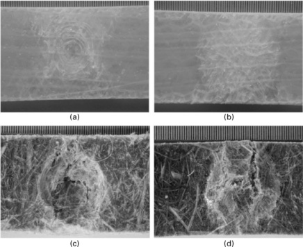
Fig. 11.32 Low-velocity impact damage of ± 45° glass fibre and hemp reinforced composites following impact of energy 5 J: (a) glass fibre impact face; (c) glass fibre, back face; (c) hemp fibre, impact face; (d) hemp fibre, back face (scale bar lines at 0.5 mm intervals). Reprinted with permission from Tong and Isaac.146
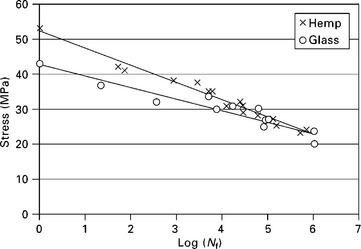
Fig. 11.33 S-N fatigue lifetime data for hemp fibre mat reinforced polyester and ± 45° glass fibre reinforced polyester. Reprinted with permission from Tong and Isaac.146
11.9 Wood-based composites
Wood, a ligno-cellulosic material, produced by trees, has a structure that permits the passage of moisture. The fatigue properties of wood were studied earlier in tension, compression and shear mode.147,148 An investigation into the fatigue performance of wood-reinforced composites was accelerated when these composites began being employed in the construction of bridges (timber bridges), wind turbine blades and panel products. Wood-based composites experience property changes such as a change in the dynamic modulus or a change in the hysteresis loop area in a similar way to traditional fibre composites. Infra-red thermography and environmental scanning electron microscopy are important tools used to investigate the mechanism of damage development in wood/natural fibre reinforced composites.149
Designers generally sum up fatigue performance as an additional property along with other general concerns for particle board and plywood applications. For structural applications such as wood roof truss and flooring, framing, and bracing systems in a structure that undergoes cyclic loading, many of the wooden materials fail at the connector junctions by fastener withdrawal, glue line separation or truss plate failure. Research focused on the fatigue properties of wood-based panels showed that in terms of the trends in fatigue life, the nature of property changes bear considerable resemblance to those for fibre reinforced composite materials. An evolution of S–N curves, constant life lines and life prediction models match well for traditional synthetic fibre reinforced composites and natural fibre reinforced composites. A distinguishing point is that the natural fibres have a cellular structure. Even though the natural fibre composites exhibit similar failure mechanisms such as compressive splitting and kinking, the characterization within the cell walls of the natural fibres is rather difficult. However, in spite of the various natural fibre species and the composite products they make available for engineering applications, fatigue performance, in general, depends on moisture content and density.149,150
The failure of wood-based components owing to fatigue and under static/quasi-static conditions are difficult to distinguish (Fig. 11.34).150 With wood-based materials, one must consider the hygroscopic and rheological aspects of the cellulosic structure when suggesting any theory and this must be coupled with the cylindrically anisotropic nature of wood.

Fig. 11.34 (a) Static tensile test fracture of southern yellow pine showing the preferred fracture path around crossing cells (rays) or holes (pits). (b) Fatigue tensile failure of the same material at approximately 5000 cycles at 80% of ultimate showing no observable change in fracture morphology (× 100). Reprinted with permission from Kyanka.150
11.10 Conclusions
Natural fibres and their composites are readily accepted instead of petroleum-based plastics for noncritical applications because of the combined endeavours of scientists, the government and interested parties in exploring the wide range of applications of NFPCs. These products are not only ecologically beneficial, but also commercially viable, and sustainable. However, there are some concerns over the complete replacement of conventional materials for durability and long-term performance. Furthermore, for outdoor applications, weathering conditions such as humidity, temperature and UV radiation impact adversely on the service life of the product. Several other factors that affect the creep resistance of natural fibre polymer composites are: type of polymer matrix, loading of the natural fibre and other additives. The incorporation of natural fibres into the polymer matrix greatly enhances the creep resistance of polymer composites. The effect of a coupling agent on the creep resistance of polymer composites depends on the modulus of the composite and the coupling effect. Higher temperatures lead to not only larger instantaneous deformation but also to long-term creep rates.
The fatigue properties of composites in general depend on the polymer type (brittle or soft matrix)/structure, MW, crosslinking, type of filler and its content, and, most importantly, on the interfacial strength. It is of paramount importance for design engineers to comprehend the fatigue phenomenon in natural fibre reinforced composites as it actuates design failures. Increasing understanding of property degradation mechanisms during service, and acquiring the ability to anticipate the life of natural fibre composites under defined conditions, will allow designers to develop materials with more reliable and desirable characteristics. Owing to their organic nature and high moisture absorption behaviour, the rate of degradation of the mechanical properties of natural fibre reinforced composites is comparatively high compared with that of synthetic fibre reinforced composites. Research is actively ongoing to employ these eco-friendly, inexpensive natural fibres in polymer matrices to give materials with enhanced mechanical properties that are hardly affected by ageing. With the increased potential of exploring their applications in areas such as motor vehicles, buildings, and in primary structures, a fundamental study of the fatigue properties of natural fibre composites is necessary.
11.11 Acknowledgements
The authors would like to thank Ontario Ministry of Agriculture, Food and Rural Affairs (OMAFRA)-2008 New Directions Research Program Project number SR9211, ‘Co-injection molded biodegradable green composites from engineered biomass-based biofibers and bioplastics’ for its financial support to carry out this research work.
11.12 Notation
| a | amplitude of transient creep strain |
| A0 | slope of the power law model |
| b | time exponent |
| D | creep compliance |
| E | equilibrium modulus |
| Ec | modulus of the composite |
| Em | modulus of the matrix |
| E(t) | stress at a given time t |
| E(t = 0) | initial stress |
| f | fibre volume fraction |
| R | universal gas constant |
| R | stress ratio |
| t | time (s) |
| T | temperature at which the test is performed (K) |
| T0 | reference temperature (K) |
| αT | horizontal shift factor |
| Γm | fracture energy for the matrix |
| ε | strain |
| ε(t) | time dependent creep strain at time t |
| ε0 | instantaneous (elastic) strain, |
| η | equilibrium viscosity |
| σ | stress |
| σc | stress required to initiate the crack (in matrix) |
| τ | interfacial shear stress |
11.12.1 Abbreviations
| ACPHB | acetone-treated PHB |
| ACPLLA | acetone-treated PLLA |
| ASCE | American Society of Civil Engineers |
| CF | carbon fibre |
| DMA | dynamic mechanical analysis |
| DMTA | dynamic mechanical thermal analysis |
| FRPC | fibre reinforced plastic composites |
| GTA | glyceryl triacetate |
| HBP | hyperbranched polyester |
| HDPE | high-density polyethylene |
| MAH-PP | maleic anhydride modified polypropylene |
| NR | natural rubber |
| NFPC | natural fibres reinforced polymer composites |
| OPFBF | oil palm fruit bunch fibre |
| PEG | polyethylene glycol |
| PHB | poly(3-hydroxybutyrate) |
| PLLA | poly-(L-lactide acid) |
| PP | polypropylene |
| PPMAN | polypropylene maleic anhydride copolymer |
| TDP | thiodiphenol |
| PVC | poly(vinyl chloride) |
| TBC | tributyl citrate |
| TEC | triethyl citrate |
| S–N curve | stress–number of cycles curve |
| TTS | time–temperature superposition |
| UD | unidirectional |
| UNPHB | unmodified PHB |
| UNPLLA | unmodified PLLA |
| UV | ultraviolet |
| WLF | Williams–Landel–Ferry |
11.13 References
1. Thomas, L., Steve, C., Robert, F., Colin, F. Accelerated weathering of natural fibre-filled polyethylene composites. Journal of Materials in civil Engineering. 2004; 16(6):547–555.
2. Lopez, J.L., Sain, M., Cooper, P. Performance of natural-fibre-plastic composites under stress for outdoor applications: effect of moisture, temperature, and ultraviolet light exposure. Journal of Applied Polymer Science. 2006; 99:2570–2578.
3. M Wolcott, P Smith, J Hermanson. 8th international conference on woodfibre-plastic composites, Madison, WI.
4. Eckert, C. Opportunities for natural fibres in plastic composites. Proceedings of the conference on the progress in woodfibre–plastic composite conference. University of Toronto, Ontario, Canada, 2000. [May 25–26].
5. Brosius, D. Natural fibre composites slowly take root. Composites Technology; 2006. [Feb.].
6. Rowell, R.M. Property enhanced natural fibre composite materials based on chemical modification. In: Prasad P.N., et al, eds. Science and technology of polymers and advanced materials. New York: Plenum Press; 1998:717.
7. Nunez, A.J., Marcovich, N.E., Aranguren, M.I. Analysis of the creep behavior of polypropylene – woodflour composites. Polymer Engineering and Science. 2004; 44(8):1594–1603.
8. Ward, I.M., Hadley, D.W. An introduction to the mechanical properties of solid polymers. Chichester: Wiley; 1993.
9. Nielsen, L.E., Landel, R.F. Mechanical properties of polymers and composites. New York: M Dekker; 1994.
10. Rodriguez, F. Principles of polymer systems. Washington, DC: Taylor & Francis; 1996.
11. Lakes, R.S. Viscoelastic solids. Boca Raton, FL: CRC Press; 1999.
12. Crawford, R.J. Plastics engineering. Oxford: Butterworth–Heinemann; 1998.
13. A A Ogale. Creep behaviour of thermoplastic composites, Thermoplastics Composite Materials, ed. L. A Charlsson. Elsevier Science Publisher, 205–232.
14. Bikiaris, D., Matzinos, P., Larena, A., Flaris, V., Panayiotou, C. Use of silane agents and poly(propylene-g-maleic anhydride) copolymer as adhesion promoters in glass fibre/polypropylene composites. Journal of Applied Polymer Science. 2001; 81(3):701–709.
15. Zafeiropoulos, N.E., Williams, D.R., Baillie, C.A., Matthews, F.L. Engineering and characterization of the interface in flax fibre/polypropylene composite materials. Part I. Development and investigation of surface treatments. Composites, Part A: Applied Science and Manufacturing. 2002; 33(8):1083–1093.
16. Arnson, T., Crouse, B., Griggs, W.Reynolds W.F., ed. The sizing of paper, 2, Atlanta Tappi Press, 1989.
17. Rozman, H.D., Tan, K.W., Kumar, R.N., Abubakar, A., Ishak, M., Ismail, H. The effect of lignin as a compatibilizer on the physical properties of coconut fibre-polypropylene composites. European Polymer Journal. 2000; 36(7):1483–1494.
18. Thielemans, W., Wool, R.P. Butyrated kraft lignin as compatibilizing agent for natural fibre reinforced thermoset composites. Composites, Part A: Applied Science and Manufacturing. 2004; 35(3):327–338.
19. Fridley, K.J. Design for creep in wood structures. Forests Products Journal. 1992; 42(3):23–28.
20. Fridley, K.J., Creep rupture behaviour of woodAgricultural Experiment Station Bulletin SB-637. Purdue University, 1992.
21. Mason, S.G. The rheology of paper; a new approach to the study of paper strength. Pulp Paper Mag. canada. 1948; 49(3):207–217.
22. Merdas, I., Thominette, F., Tcharkhtchi, A., Verdu, J. Factors governing water absorption by composite matrices. Composites Science and Technology. 2002; 62(4):487–492.
23. Yang, H.S., Kim, H.J., Park, H.J., Lee, B.J., Hwang, T.S. Water absorption behavior and mechanical properties of lignocellulosic filler–polyolefin bio-composites. Composite Structures. 2006; 72(4):429–437.
24. Kazemi Najafi, S., Hamidinia, E., Tajvidi, M. Mechanical properties of composites from sawdust and recycled plastics. Journal of Applied Polymer Science. 2006; 100(5):3641–3645.
25. Kazemi Najafi, S., Sharifnia, H., Tajvidi, M. Effects of water absorption on creep behavior of wood-plastic composites. Journal of composite Materials. 2008; 42(10):993–1002.
26. Bledzki, A.K., Faruk, O. Creep and impact properties of wood fibre–polypropylene composites: influence of temperature and moisture content. Composites Science and Technology. 2004; 64:693–700.
27. Pooler, D.J., Smith, L.V. Nonlinear viscoelastic response of a wood–plastic composite including temperature effects. Journal of Thermoplastic Materials. 2004; 17:427–445.
28. Singh, S., Mohanty, A.K. Composites Science and Technology. 2007; 67:1753–1763.
29. Singh, S., Mohanty, A.K., Sugie, T., Takai, Y., Hamada, H. Composites: Part A. 2008; 39:875–886.
30. Jiang, L., Huang, J., Qian, J., Chen, F., Zhang, J., Wolcott, M.P., Zhu, Y.J. Polym. Environ.. 2008; 16:83–93.
31. Kiguchi, M. Latest market status of wood and wood plastic composites in North America and Europe. The Second Wood and Wood Plastic Composites Seminar in the 23rd Wood Composite Symposium. 2007:61–73. [Kyoto, Japan].
32. Panthanpulakkal, S., Sain, M. Compos. A. 2007; 38:1445–1454.
33. Xu, Y., Creep behaviour of natural fibre reinforced polymer compositesPhD dissertation. Lousiana State University, 2009. [Dec,].
34. Xu, Y., Wu, Q., Lei, Y., Yao, F. Creep behavior of bagasse fibre reinforced polymer composites. Bioresource Technology. 2010; 101(9):3280–3286.
35. Acha, A.B., Reboredo, M.M., Marcovich, N.E. Creep and dynamic mechanical behavior of PP–jute composites: effect of the interfacial adhesion. Composites, Part A: Applied Science and Manufacturing. 2007; 38(6):1507–1516.
36. Houshyar, S., Shanks, R.A., Hodzic, A. Tensile creep behaviour of polypropylene fibre reinforced polypropylene composites. Polymer Testing. 2005; 24(2):257–264.
37. Acha, A.B., Reboredo, M.M., Marcovich, N.E. Effect of coupling agents on the thermal and mechanical properties of polypropylene-jute fabric composites. Polymer International. 2006; 55(9):1104–1113.
38. Read, B.E., Tomlins, P.E., Dean, G.D. Physical ageing and short-term creep in amorphous and semicrystalline polymers. Polymer. 1990; 31(7):1204–1215.
39. Tomlins, P.E., Read, B.E. Creep and physical ageing of polypropylene: a comparison of models. Polymer. 1998; 39(2):355–367.
40. Matsumoto, D.S. Time temperature superposition and physical ageing in amorphous polymers. Polymer Engineering and Science. 1988; 28:1313–1317.
41. Wong, S., Shanks, R. Creep behaviour of biopolymers and modified flax fibre composites. Composite Interfaces. 2008; 15(2–3):131–145.
42. William, M.L., Landel, R.F., Ferry, J.D. The temperature dependence of relaxation mechanism in amorphous polymer and other glass-forming liquids. Journal of the American Chemical Society. 1955; 77:3701–3707.
43. Ward, I.M. Mechanical properties of solid polymers. Wiley Interscience; 1971.
44. Ferry, J.D. Viscoelastic properties of polymer. John Wiley and Sons Inc; 1961.
45. T Yeow, D H Morris, H F Brinson. A new experimental method for the accelerated characterization of composites material. VPI-E-78-3.
46. McNaught, A.D., Wilkinson, A. Arrhenius equation IUPAC Gold Book, 1997.
47. Nielsen, L.E., Landel, R.F. Mechanical properties of polymers and composites, 2nd ed. New York: Marcel Dekker; 1994.
48. Faucher, J.A. Viscoelastic behavior of polyethylene and polypropylene. Transaction of the Society of Rheology. 1959; 3:81–93.
49. Ward, I.M. An introduction to the mechanical properties of solid polymers, 2nd ed. Chichester, UK: John Wiley & Sons; 2004.
50. Nielsen, L.E., Landel, R.F. Mechanical properties of polymers and composites, 2nd ed. New York: Marcel Dekker; 1994.
51. Dutta, N.K., Graham, E.H. Generic relaxation spectra of solid polymers. I. Development of spectral distribution model and its application to stress relaxation of polypropylene. Journal of Applied Polymer Science. 1997; 66(6):1101–1115.
52. Nitta, K., Suzuki, K. Prediction of stress-relaxation behavior in high density polyethylene solids. Macromolecular Theory and Simulations. 1999; 8:254–259.
53. B D Harper, Y Weitsman. Characterization method for a class of thermorheologically complex materials, Journal of Rheology, 29(1), 49–66.
54. Tajvidi, M., Falk, R.H., Hermanson, J.C. Time–temperature superposition principle applied to a kenaf-fibre/high-density polyethylene composite. Journal of Applied Polymer Science. 2005; 97(5):1995–2004.
55. Findley, N., Lai, J.S., Onaran, K. Creep and stress relaxation of non-linear viscoelastic materials. New York: Dover Publications; 1976.
56. Jiang, L., Wolcott, M.P., Zhang, J.W., Englund, K. Flexural properties of surface reinforced wood/plastic deck board. Polymer Engineering and Science. 2000; 47:281–288.
57. Yang, S.W., Chin, W.K. Mechanical properties of aligned long glass fibre reinforced polypropylene. II: tensile creep behaviour. Polymer Composites. 1999; 20(2):207–215.
58. Findley, W.N., Khosla, G. Application of the superposition principle and theories of mechanical equation of state, strain, and time hardening to creep of plastics under changing loads. Journal of Applied Physics. 1955; 26(7):821–832.
59. Bank, L.C., Mosallam, A.S. Creep and failure of a full size fibre reinforced plastic pultruded frame. Composites Engineering. 1990; 2(3):217–227.
60. American Society of Civil Engineers. Structural plastic design manual. ASCE Publications.
61. Marais, C., Villoutreix, G. Analysis and modeling of the creep behavior of the thermostable PMR-15 polyimide. Journal of Applied Polymer Science. 1998; 69(10):1983–1991.
62. Matsumoto, D.S. Time–temperature superposition and physical aging in amorphous polymers. Polymer Engineering and Science. 1988; 28:1313–1317.
63. Dean, D., Husband, M., Trimmer, M. Time-temperature-dependent behavior of a substituted poly(paraphenylene): Tensile, creep, and dynamic mechanical properties in the glassy state. Journal of Polymer Science Part B: Polymer Physics. 1998; 36(16):2971–2979.
64. Brinson, L.C., Gates, T.S. Effects of physical aging on long term creep of polymers and polymer matrix composites. International Journal of Solids and Structures. 1995; 32(6–7):827–846.
65. Rangaraj, S.V., Smith, L.V. The nonlinearly viscoelastic response of a wood–thermoplastic composite. Mechanics of Time-Dependent Materials. 1999; 3(2):125–139.
66. Pramanick, A., Sain, M. Application of the ‘theory of mixtures’ to temperature–stress equivalency in nonlinear creep of thermoplastic/agro-fibre composites. Polymers & Polymer Composites. 2006; 14(5):455–472.
67. Pramanick, A., Sain, M. Nonlinear viscoelastic creep characterization of HDPE – rice husk composites. Polymers & Polymer Composites. 2005; 13(6):581–598.
68. Lin, W.S., Pramanick, A.K., Sain, M. Determination of material constants for nonlinear viscoelastic predictive model. Journal of composite Materials. 2004; 38(1):19–29.
69. George, J., Sreekala, M.S., Thomas, S., Bhagwan, S.S., Neelakantan, N.R. Stress relaxation behaviour of short pineapple fibre reinforced polyethylene composites. Journal of Reinforced Plastics and composites. 1998; 17:651–672.
70. George, T.J., Bhagwan, S.S., Thomas, S. Improved interactions in chemically modified pineapple leaf fibre reinforced polyethylene composites. Composites Interfaces. 1997; 5(3):201–223.
71. George, T.J., Bhagwan, S.S., Prabhakaran, N. Short pineapple leaf fibre reinforced low density polyethylene composites. Journal of Applied Polymer Science. 1995; 57(7):843–854.
72. George, T.J., Bhagwan, S.S. Effects of environment on the properties of low density polyethylene composites reinforced with pineapple leaf fibre. Composites Science and Technology. 1998; 58:1471–1485.
73. Geethamma, V.G., Pothen, L.A., Rhao, B., Neelakantan, N.R., Thomas, S. Tensile stress relaxation of short-coir-fibre-reinforced natural rubber composites. Journal of Applied Polymer Science. 2004; 94(1):96–104.
74. Wortmann, J., Schulz, K.V. Stress relaxation and time temperature superposition of polypropylene fibres. Polymer. 1995; 36:315–321.
75. O’Connel, P.A., McKenna, G.B. Large deformation response of polycarbonate: time–temperature, time aging time, and time–strain superposition. Polymer Engineering and Science. 1997; 37:1485–1495.
76. Lai, J.S., Findley, W.N. Sress relaxation of non-linear viscoelastic material under uniaxial strain. Transaction of the Society of Rheology. 1968; 12:259–280.
77. Gent, A.N. Relaxation processes in vulcanized rubber. III. Relaxation at large strains and the effect of fillers. Rubber Chemistry and Technology. 1963; 36(3):697–708.
78. Bhagawan, S.S., Tripathy, D.K., De, S.K. Stress relaxation in short jute fibre-reinforced nitrile rubber composites. Journal of Applied Polymer Science. 1987; 33(5):1623–1639.
79. Flink, P., Stenberg, B. An indirect method which ranks the adhesion in natural rubber filled with different types of cellulose fibres by plots of E(t)/E(t = 0) versus log(t). British Polymer Journal. 1990; 22:193–197.
80. Kutty, S.K.N., Nando, G.B. Stress relaxation behaviour of short kevlar fibre reinforced thermoplastic polyurethane. Journal of Applied Polymer Science. 1991; 42(7):1835–1844.
81. Sircar, A.K., Voet, A., Cook, F.R. Relaxation of stress and electrical resistivity in carbon-filled vulcanizates at moderate and high extensions. Rubber Chemistry and Technology. 1971; 44(1):185–198.
82. Gent, A.N. Crystallization and the relaxation of stress in stretched natural-rubber vulcanizates. Transactions of the Faraday Society. 1954; 50:521–533.
83. Varghese, S., Kuriakose, B., Thomas, S., Koshy, T.A. Dynamic mechanical properties of short sisal fibre reinforced natural rubber composites. The Indian Journal of Natural Rubber Research. 1991; 4(1):55–67.
84. Varghese, S., Kuriakose, B., Thomas, S. Stress relaxation in short sisal-fiber-reinforced natural rubber composites. Journal of Applied Polymer Science. 1994; 53(8):1051–1060.
85. Subramanian, S., Reifsnider, K.L., Stinchcomb, W.W. A cumulative damage model to predict the fatigue life of composite laminates including the effect of a fibre–matrix interphase. International Journal of Fatigue. 1995; 17(5):343–351.
86. Dharan, K.H. Interlaminar shear fatigue of pultruded graphite fibre–polyester composites. Journal of Materials Science. 1978; 13:1243–1248.
87. Hitchen, S.A., Ogin, S.L., Smith, P.A. Effect of fibre length on fatigue of short carbon fibre/epoxy composite. Composites. 1996; 26(4):303–310.
88. Gamstedt, E.K., Talreja, R. Fatigue damage mechanisms in unidirectional carbon-fibre-reinforced plastics. Journal of Materials Science. 1999; 34:2535–2546.
89. Harris B., ed. Fatigue in composites: Science and technology of the fatigue response of fibre-reinforced plastics. Cambridge: Woodhead Publishing, 2003.
90. Gamstedt, E.K., Berglund, L.A., Peijs, T. Fatigue mechanisms in unidirectional glass–fibre-reinforced polypropylene. Composites Science and Technology. 1999; 59:759–768.
91. Lamela, M.J., Canteli, A.F., Reiter, H., Harris, B. Comparative statistical analysis of the fatigue of composites under different modes of loading. Journal of Materials Science. 1997; 32:6495–6503.
92. Otani, N., Song, D.Y. Fatigue life prediction of composites under two-stage loading. Journal of Materials Science. 1997; 32:755–760.
93. Paepegem, W.V., Degrieck, J. Modelling damage and permanent strain in fibre-reinforced composites under in-plane fatigue loading. Composites Science and Technology. 2003; 63:677–694.
94. Gassan, J., Bledzki, A.K. June 19–21,. 7th International Techtextil Symposium. 1995.
95. A K Bledzki, S Reihmane, J Gassan. Properties and modification methods for vegetable fibres for natural fibre composites. Journal of Applied Polymer Science, 59, 1329–1336.
96. Lee, S.M., Rowell, R.M. International Encyclopedia of Composites, 4, New York: VCH, 1991. [4,].
97. Fink, H.P., Proceedings Akzo-Nobel Viscose Chemistry Seminar, Challenges in Cellulosic Man-Made Fibres, May 30–June 3, 1994.
98. Fink, H.P., Ganster, J., Fraatz, J., Nywlt, M. Relations between structure and mechanical properties of cellulosic man-made fibres. Azko Nobel Viscose Chemistry Seminar ‘Challenges in cellulosic man-made fibres’. 1994. [Stockholm,].
99. Mwaikambo, L.Plant-based resources for sustainable composites, PhD Thesis. University of Bath, 2002.
100. Ray, P.K., Chakravarty, A.C., Bandyopadhyay, S.B. Fine structure and mechanical properties of jute differently dried after retting. Journal of Applied Polymer Science. 1976; 20(7):1765–1767.
101. Semsazadeh, M.A. Fibre matrix interactions in jute reinforced polyester resin. Polymer Composites. 1986; 71(1):23–25.
102. Bisanda, E.T.N., Ansell, M.P. The effect of silane treatment on the mechanical and physical properties of sisal–epoxy composites. Composites Science and Technology. 1991; 41(2):165–178.
103. Zeronian, S.H., Kawabata, H. Factors affecting the tensile properties of nonmercerized and mercerized cotton fibres. Textile Research Journal. 1990; 60(3):179–183.
104. Zoolagud, S.S. T S Rangaraju. Plant Fibres News. 1997; 71:6.
105. Mishra, S., Naik, J.B. Absorption of steam and water at ambient temperature in wood polymer composites prepared from agro-waste and Novolac. Journal of Applied Polymer Science. 1998; 68(9):1417–1421.
106. Millman, A.F. Strain limited design criteria for reinforced plastic process equipment. 34th Annual Technical Conference of the SPL, Sect. 3D. 1979.
107. Riccieri, J.E., Vázquez, A., Hecker, L., Carvalho, D. Interfacial properties and initial step of the water sorption in unidirectional unsaturated polyester/vegetable fibre composites. Polymer Composites. 1999; 20(1):29–37.
108. Woodhams, R.T., Thomas, G.T., Rodgers, D.K. Wood fibres as reinforcing fillers for polyolefins. Polymer Engineering and Science. 1984; 24(15):1166–1171.
109. Hua, L., Flodin, P., Rönnhult, T. Cellulose fibre-polyester composites with reduced water sensitivity. 2. Surface analysis. Polymer Composites. 1987; 8(3):203–207.
110. Mark H.F., Gaylord N.C., Bikales N.M., eds. Encyclopedia of polymer science and technology. New York: Wiley-Interscience, 1970. [12, 1.].
111. Bisanda, E.T.N. The effect of alkali treatment on the adhesion characteristics of sisal fibres. Applied composite Materials. 2000; 7:331–339.
112. Chand, N., Rohatgi, P.K. Adhesion of sisal fibre–polyester system. Polym Comm. 1986; 27:157–160.
113. Cox, B.N., Marshall, D.B. Crack bridging in the fatigue of fibrous composites. Fatigue & Fracture of Engineering Materials & Structures. 1991; 14(8):847–861.
114. Bao, G., Song, Y. Crack bridging models for fibre composites with slip-dependent interfaces. Journal of the Mechanics and Physics of Solids. 1993; 41(9):14251444.
115. Newaz, G.M., Bonora, N. Damage based fatigue life modeling for brittle composites, 1997. [ICCM-11, Gold Coast, Australia,].
116. Gassan, J. A study of fibre and interface parameters affecting the fatigue behaviour of natural fibre composites. Composites Part A: Applied Science and Manufacturing. 2002; 33(3):369–374.
117. Gassan, J. Naturfaserverstärkte Kunststoffe: Korrelation zwischen Struktur und Eigenschaften der Fasern und deren Composites. PhD Dissertation. Kassel: University of Kassel; 1997.
118. Hamad, W.Y. On the mechanisms of cumulative damage and fracture in native cellulose fibres. Journal of Materials Science Letters. 1998; 17(5):433–436.
119. Reifsnider, K.L., Schulte, K., Duke, J.C. Long-term fatigue behaviour of composite materials. In: O’Brien T.K., ed. Long-term behaviour of composites. Philadelphia: ASTM; 1983:813.
120. Newaz, G.M. A quantitative assessment of debonding in unidirectional composites under long-term loading. Journal of Reinforced Plastics and composites. 1985; 4(4):354–364.
121. Ramakrishnan, V., Jayaraman, N.N. Mechanistically based fatigue-damage evolution model for brittle matrix fibre-reinforced composites. Journal of Materials Science. 1993; 28(20):5592–5602.
122. Gassan, J. Fatigue behavior of cross-ply glass-fibre epoxy composites including the effect of fibre-matrix interphase. Composite Interfaces. 2000; 7(4):287–299.
123. Gassan, J., Bledzki, A.K. Possibilities to improve the properties of natural fibre reinforced plastics by fibre modification – jute polypropylene composites. Applied composite Materials. 2000; 7(5–6):373–385.
124. Gassan, J., Bledzki, A.K. Dynamic-mechanical properties of natural fibre-reinforced plastics: the effect of coupling agents. Fourth International Conference on Woodfibre–Plastic Composites. Madison, USA, 1997:12–14. [May,].
125. Gassan, J., Bledzki, A.K. Effect of moisture content on the properties of silanized jute-epoxy composites. Polymer Composites. 1997; 18(2):179–184.
126. Lundemo, C. Fatigue of fibre-reinforced plastics: a literature survey. Stockholm: Report of the Aeronautical Research Institute of Sweden (FFA-TN-Au-1499); 1979.
127. Talreja, R. Fatigue of Composite Materials: damage mechanisms and fatigue-life diagrams. Proceedings of the Royal Society, London. 1981; 378:461.
128. Gassan, J., Mildner, I., Bledzki, A.K. Influence of fibre structure modification on the mechanical properties of flax fibre-epoxy composites. Mechanics of Composite Materials. 2000; 35(5):435–440. [(Translation of Mekhanika Kompozitnykh Materialov (Zinatne)),].
129. Zok, F.W., Spearing, S.M. Matrix crack spacing in brittle matrix composites. Acta Metallurgica et Materialia. 1992; 40(8):2033–2043.
130. Gassan, J., Bledzki, A.K. Alkali treatment of jute fibres: Relationship between structure and mechanical properties. Journal of Applied Polymer Science. 1999; 71:623–629.
131. Mukherjee, A., Ganguly, P.K., Sur, D. Structural mechanics of jute: The effects of hemicellulose or lignin removal. Journal of the Textile Institute Transactions. 1993; 84:348–353.
132. Varma, D.S., Varma, M., Varma, I.K. Journal of the Textile Institute. 1984; 54:349.
133. Sreenivasan, S., Iyer, B.P., Iyer, K.K.R. Influence of delignification and alkali treatment on the fine structure of coir fibres. Journal of Materials Science. 1996; 31(3):721–726.
134. Sharma, H.S., Fraser, T.W., McCall, D., Lyons, G. Fine structure of chemically modified flax fibre. Journal of the Textile Institute. 1995; 86(4):539–548.
135. Shelat, B.R., Radhakrishnan, T., Iyer, B.V. The relation between crystallite orientation and mechanical properties of mercerized cottons. Textile Research Journal. 1960; 33:836–842.
136. Gassan, J., Bledzki, A.K. The influence of fibre-surface treatment on the mechanical properties of jute-polypropylene composites. Composites Part A: Applied Science and Manufacturing. 1997; 28(12):1001–1005.
137. Mieck, K.P., Nechwatal, A., Knobelsdorf, C. Faser-Marix-Haftung in Kunstoffverbunden aus thermoplastischer Matrix und Flachs. Angewandte Makromolekulare Chemie. 1995; 224(1):73–88.
138. Ray, D., Sarkar, B.K., Bose, N.R. Impact fatigue behaviour of vinylester resin matrix composites reinforced with alkali treated jute fibres. Composites Part A: Applied Science and Manufacturing. 2002; 33(2):233–241.
139. Moe, T., Kin, L. Durability of bamboo–glass fibre reinforced polymer matrix hybrid composites. Composites Science and Technology. 2003; 63(3–4):375–387.
140. Bond, I.P., Ansell, M.P. Fatigue properties of jointed wood composites. Part I. Statistical analysis, fatigue master curves and constant life diagrams. Journal of Materials Science. 1998; 33:2751–2762.
141. Harris, B., Gathercole, N., Lee, J.A., Reiter, H., Adam, T. Life-prediction for constant-stress fatigue in carbon–fibre composites. Phil Trans R Soc Lond A. 1997; 355:1259–1294.
142. Towo, A.N., Ansell, M.P. Fatigue evaluation and dynamic mechanical thermal analysis of sisal fibre thermosetting resin composites. Composites Science and Technology. 2008; 68(3–4):925–932.
143. Towo, A.N., Ansell, M.P. Fatigue of sisal fibre reinforced composites: Constant-life diagrams and hysteresis loop capture. Composites Science and Technology. 2008; 68(3–4):915–924.
144. Hacker, C.L., Ansell, M.P. Fatigue damage and hysteresis in wood–epoxy laminates. Journal of Materials Science. 2001; 36:609–621.
145. Tong, Y. D H Isaac. Impact and fatigue behaviour of hemp fibre composites. Composites Science and Technology. 2007; 67(15–16):3300–3307.
146. Tsai, K.T., Ansell, M.P. Fatigue properties of wood in flexure. Journal of Materials Science. 1990; 25:865–878.
147. Bonfield, P.W., Ansell, M.P. Fatigue properties of wood in tension, compression and shear. Journal of Materials Science. 1991; 26:4765–4773.
148. Ansell, M.P. Fatigue of wood and wood panel products. In: Harris Bryan, ed. Fatigue in composites. CRC press; 2003:339–360.
149. Kyanka, G. Fatigue properties of wood and wood composites. International Journal of Fracture. 1980; 16(6):609–616.
150. Thompson, R.J.H., Ansell, M.P., Bonfield, P.W., Dinwoodie, J.M. Fatigue in wood-based panels. Part 1. The strength variability and fatigue performance of OSB, chipboard and MDF. Wood Science and Technology. 2002; 36(3):255–269.