
After the surveyors have finished their work and determined a property boundary, the next task is often to create a subdivision plan. Before Civil 3D, the designers would spend a few days sketching on paper or working through scenarios by trial and error with AutoCAD linework. With Civil 3D, the designer can work directly in the drawing with tools that automatically size parcels, as well as create dynamic labels and tables. Civil 3D makes it easy to go through more iterations of a subdivision plan in less time than traditional methods.
This chapter includes the following topics:
Converting a boundary to a parcel
Creating internal boundary segments
Creating lots at the end of a cul-de-sac
Creating evenly sized subdivision lots
Renumbering parcels
Labeling parcel segments
Analyzing parcels with an area table
Working through and finalizing a site plan
All land development projects begin with a boundary. Perhaps this boundary was created from field information and brought in using the survey tools discussed in Chapter 4, "Survey;" or maybe this boundary was created from deed research using techniques described in Chapter 3, "Lines and Curves."
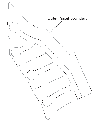
Before you can take advantage of the dynamic nature of parcels for labeling, and before you can subdivide your boundary using the automatic parceling tools, you must convert the boundary into a parcel. It is best to use a closed polyline for this outer parcel boundary.
The following exercise leads you through converting a closed polyline into a Civil 3D parcel:
Open the drawing file
Parcels1.dwg, which you can download fromwww.sybex.com/go/introducingcivil3d2010.From the Home tab's Create Design panel, select Parcel → Create Parcel from Object.
At the
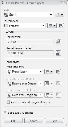
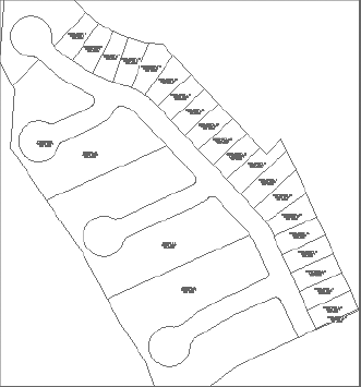
Select lines, arcs, or polylines to convert into parcels or [XREF]:prompt, select the blue colored polyline that represents the outer site boundary, as shown in Figure 6.1.Press Enter. The Create Parcels – From objects dialog will appear. Confirm that the Parcel Style is set to Property, the Area label style is set to Parcel Name, and the Erase existing entities box is checked, as shown in Figure 6.2. Click OK. Note that a parcel called Property: 1 is formed.
Zoom in on the Property: 1 label. Select the label to activate the Parcels:Property : 1 contextual tab. On the Modify panel, select Parcel Properties. The Parcel Properties dialog will appear.
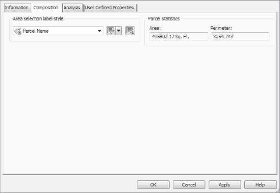
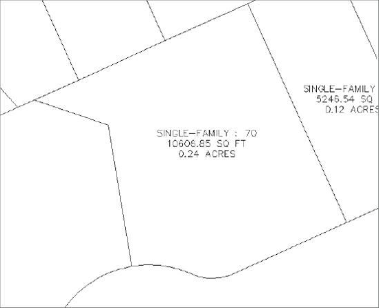
Open the Composition tab of the Parcel Properties dialog, as shown in Figure 6.3. Note that the area and perimeter of Property: 1 are shown. Use the pull-down list under Area Selection Label Style to change the area label from Parcel Name to Name Square Foot & Acres. Explore the Analysis and User Defined Properties tabs of the Parcel Properties dialog, if desired. Click OK. Note that Property: 1 is now shown with the Name Square Foot & Acres label.
Press Esc to exit the command.
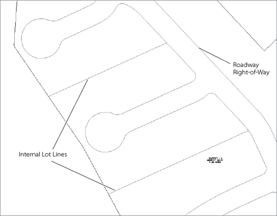
When you are working on a land development plan in Civil 3D, it is best to map out key locations on the site before you begin creating residential lots. You would use regular AutoCAD linework to sketch out areas for easements, dedications, open space, and utility lots, and then convert the linework to parcel segments. Although there is a tool to create simple right-of-way parcels based on an alignment, it is often better to create a polyline using AutoCAD tools (such as offset, fillet, circle, and more) that represents your road right-of-way.
The following exercise leads you through converting some internal boundaries into Civil 3D parcels to prepare for subdivision:
Continue working in the drawing from the previous exercise or open
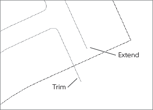
Parcels2.dwg.Zoom in on the southern portion of the site where the road right-of-way polyline intersects with the boundary parcel. Use tools such as Trim, Extend, and Join to ensure that the road right-of-way polyline touches the boundary without gap or overhang, as shown in Figure 6.4.
From the Home tab's Create Design panel, select Parcel → Create Parcel from Object.
At the
Select lines, arcs, or polylines to convert into parcels or [XREF]:prompt, select the green polyline that represents the roadway right-of-way, and the two magenta lines that represent some internal lot lines, as shown in Figure 6.5.Press Enter. The Create Parcels – From objects dialog will appear. Confirm that Parcel Style is set to Property. Change the Area Label Style to Name Square Foot & Acres. Confirm that the Erase existing entities box is checked. Click OK. Three new parcels are formed in the drawing.
When you're first learning Civil 3D, it is often tempting to rely on AutoCAD linework and then convert those lines, arcs, and polylines into parcels. Although there is nothing wrong with this approach for things like an outer boundary and some key internal lot lines, you will be missing out on some powerful functionality if you don't take time to learn and apply tools like the Free Form Create tool. The Free Form Create tool can be used before you begin working with the details of your site plan, or you can use it as a tool to refine and improve your plan once the bulk of the residential lots have been created. Once you learn how it works, you will find many other uses for it.
The following exercise introduces you to using the Free Form Create tool by leading you through making an open space lot at the end of a cul-de-sac:
Continue working in the drawing from the previous exercise or open
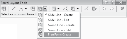
Parcels3.dwg.From the Home tab's Create Design panel, select Parcel → Parcel Creation Tools. The Parcel Layout Tools dialog will appear.
Use the Parcel Sizing tool's pull-down list to choose the Free Form Create tool, as shown in Figure 6.6. The Create Parcels – Layout dialog will appear.
In the Create Parcels – Layout dialog, change the Parcel Style to Single Family, and ensure that the Area label style is set to Name Square Foot & Acres. Leave the Automatically Add Segment Labels box unchecked. Click OK.
At the
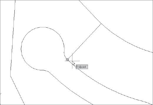
Select attachment point:prompt, use your endpoint osnap to select the beginning of the first arc on the northern cul-de-sac, as shown in Figure 6.7. A parcel segment glyph will appear.At the
Specify lot line direction (ENTER for perpendicular) or [Bearing/Azimuth]:prompt, press Enter to choose perpendicular. A lot line will be created from the right-of-way parcel line extending to the boundary parcel line.Repeat steps 5 and 6 for the other side of this cul-de-sac.
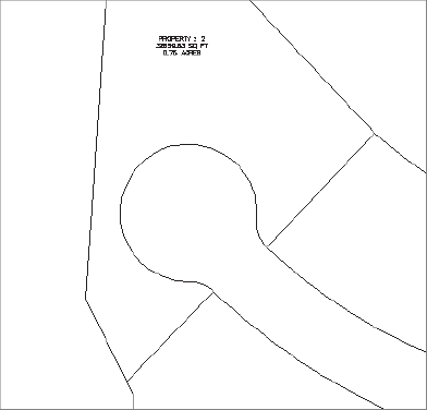
When you're finished creating lot lines, press Enter. At the
Select from the layout tools or [eXit]:prompt, type X and press Enter to exit.Note that new parcels have been formed, as shown in Figure 6.8.
Everyone working on land development plans for a subdivision wants the best design possible. The designer wants to ensure a quality layout that will meet code requirements and be livable, aesthetically appealing, and cost effective to construct. Within those constraints, the designer often struggles to maximize the number of subdivision lots. Before Civil 3D, there were no real tools to assist with this task.
The automatic parcel creation tools, such as Create Parcel by Layout, allow the designer to establish parameters and run through many iterations and configurations quickly. The more iterations that are performed, the more likely the designers will be to produce a site plan that they feel truly captures their design intent.
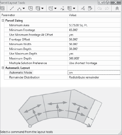
New to Civil 3D 2010 is the capability to select Minimum and Maximum frontage widths and depths. What does this mean to you? If you live in a municipality that requires a minimum frontage be established at the building setback line, it is now easily accomplished! By setting values for these options, Civil 3D will do all the grunt work for you and give you your required widths and depths. The municipality for the subdivision in this exercise does not require this, so you will bypass these options. But we want to make you aware of what they do.
You'll also notice new graphics at the bottom of the Parcel Layout Tools dialog. Depending on what option you choose, the graphic will give you a visual of what information is required.
The next exercise has you create evenly sized subdivision lots using Create Parcel by Layout.
Continue working in the drawing from the previous exercise or open
Parcels4.dwg.From the Home tab's Create Design panel, select Parcel → Parcel Creation Tools. The Parcel Layout Tools dialog will appear.
Click the chevrons button at the far-right end of the dialog to expand the Parameters list if it is not already expanded.

Change the Default Area value to 5175.00 Sq. Ft. and the Minimum Frontage value to 45.000′, as shown in Figure 6.9.
Click inside the Automatic Mode field to activate the drop-down list. Use the drop-down list to change the Automatic Mode to On.
Click inside the Remainder Distribution field to activate the drop-down list. Use the drop-down list to set the Remainder Distribution to Create Parcel from Remainder.
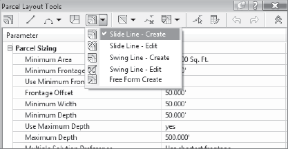
Use the Parcel Sizing Tools pull-down list to choose the Slide Line – Create tool, as shown in Figure 6.10. The Create Parcels – Layout dialog will appear.

In the Create Parcels – Layout dialog, change the Parcel Style to Single Family, and verify that the Area Label Style is set to Name Square Foot & Acres. Leave the Automatically Add Segment Labels box unchecked. Click OK.
At the
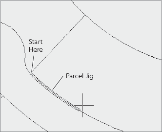
Select parcel to be subdivided or [Pick]:prompt, pick the label on the large parcel on the north side of the main road.At the
Select start point on frontage:prompt, use your endpoint osnap to select the end of the lot line that you created in the last exercise, as shown in Figure 6.11. The parcel jig will appear along the road frontage.At the
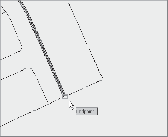
Select end point on frontage:prompt, use your endpoint osnap to select the intersection of the boundary parcel and the right-of-way parcel on the south side of the site, as shown in Figure 6.12. Note the temporary graphic on the screen. This shows you what you have picked and the direction before you commit to the changes.At the
Specify angle or [Bearing/aZimuth]:prompt, press Enter. This specifies an angle of 90 degrees. Notice that the previous graphic on the screen now has additional information. This shows you what the parcels will look like and gives you a chance to modify them before committing the changes.At the
Accept result? [Yes/No] <Yes>:prompt, press Enter. The graphic disappears, and your evenly sized subdivision lots are drawn as shown in Figure 6.13. Notice that a small remainder lot was created on the southern part of the site.Press Esc.
When you're finished creating lot lines, press Enter. At the
Select from the layout tools or [eXit]:prompt, type X and press Enter to exit.Zoom into the remainder lot. Notice that the area is only 0.01 Acres. This lot doesn't make sense, so you're going to redo the lots with the distribute method.
Using the AutoCAD Erase command, erase all of the inner lot lines. This will get you back to one lot.
Repeat steps 6 through 15, except choose the Redistribute Remainder option in step 6.
Civil 3D numbers parcels as they are created, so after a few iterations you can find yourself with some pretty odd number combinations. Also, because Civil 3D assigns numbers to your road right-of-way and open space areas, you may find yourself wondering how to make the numbers in your drawing match the numbers on an existing plat or how to please the review agency.
Renumbering parcels in Civil 3D is extremely easy. It is recommended that you wait until you have most of your site plan done before you renumber your lots so that you save yourself from having to do it over and over again. The next exercise will show you how.
Continue working in the drawing from the previous exercise or open
Parcels5.dwg.From the Modify tab and Design panel on the ribbon, select Parcel. The Parcel contextual tab will appear. From the Modify panel, select Renumber/Rename. The Renumber/Rename Parcels dialog will appear.
Confirm that the radio button next to Renumber is selected. Confirm that the Starting Number is set to 1; if not, change the Starting Number to 1. Click OK.
At the
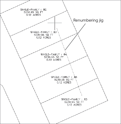
Specify start point or [Polylines/Site]:prompt, click anywhere inside the southernmost subdivision lot. The renumbering jig will appear similar to what's shown in Figure 6.14.At the
End point or [Undo]:prompt, click anywhere inside the lots on the northern side of the road right-of-way, as if you were drawing a polyline through the lots. Click inside the last lot near the cul-de-sac, and then press Enter twice. Your lots should now be renumbered with Property: 1 at the southernmost point.
Although you may be able to submit a preliminary site plan without a full set of labels, most final plats require detailed labeling of parcel segments to confirm that lengths and radii meet code specifications, to assist with stakeout, and for writing legal descriptions for deeds.
It is recommended that you wait until you have most of your site plan done before you proceed with detailed labeling. The next exercise will lead you through adding labels to parcel segments.
Continue working in the drawing from the previous exercise or open
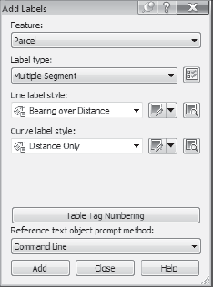
Parcels6.dwg.Change to the Annotate tab, and from the Labels & Tables panel, select Add Labels → Parcel → Add Parcel Labels. The Add Labels dialog will appear as shown in Figure 6.15.
Use the Label Type pull-down menu to choose Multiple Segment.
Use the Line Label Style pull-down menu to select Bearing over Distance, if it's not already selected.
Use the Curve Label Style pull-down menu to select Distance Only.
Click Add.
At the
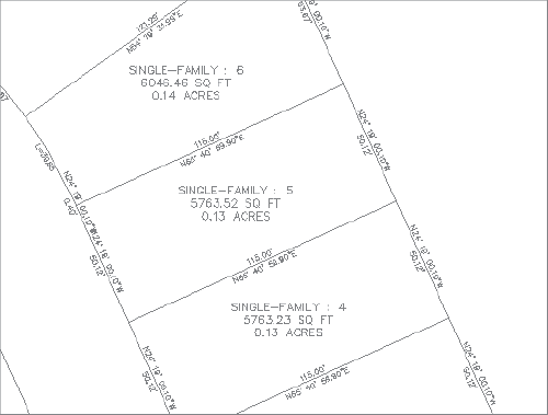
Select parcel to be labeled by clicking on area label:prompt, click the area label for Property: 1.At the
Label direction [CLockwise/COunterclockwise] <CLOckwise>:prompt, press Enter. Labels will appear along each parcel segment.Repeat steps 7 and 8 for all of the subdivision lot parcels created in the previous exercise, and then click the Close button to dismiss the Add Labels dialog. The labels will appear as shown in Figure 6.16.
Most land planners are required to bring site plans to hearings or through some kind of review process. The review agency typically wants to know if the site plan meets minimum lot-size requirements and other data that is best presented in table form. Civil 3D parcel area tables provide a great way to present much of this data. The following exercise leads you through a simple example, but you should also explore ways to add more information to your parcels through user-defined properties.
Continue working in the drawing from the previous exercise or open
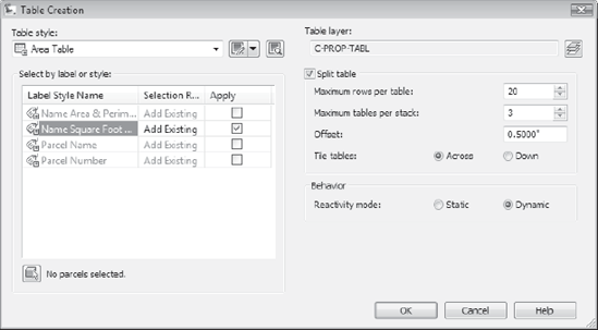
Parcels7.dwg.From the Modify tab and Design panel on the ribbon, choose Parcel. The Parcel contextual tab will appear. From the Labels & Tables panel, select Add Tables → Add Area. The Table Creation dialog will appear.
Select Area Table from the Table style: pull-down list if it's not already selected.
Check the box next to Name Square Foot & Acres. This will select all parcels labeled with the Name Square Foot & Acres label for the area table, as shown in Figure 6.17. Click OK.
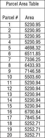
At the
Select upper left corner:prompt, place the area table somewhere in the open space to the right of the site plan. The area table will appear. The table should look similar to Figure 6.18 (although the parcel numbers and areas may be different in your table).Save your drawing—you will use it to finalize your plan.
So far in this chapter, you managed to lay out lots on one side of the street, but what about the rest of the site? Use the next section as a reference to help you experiment with this site plan and later work through your own plans.
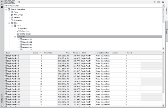
As you learn more about Civil 3D, you will begin to use the Prospector tab of the Civil 3D Toolspace as your master control center. As Civil 3D objects are created, they populate Prospector. Parcels are no exception. You will find your parcels in the Sites collection in Prospector, as shown in Figure 6.19. Use the item view to sort parcels, examine them, and make batch changes to parcel styles, label styles, and more. Right-click a parcel entry to zoom to that specific parcel.
Your first iteration using the automatic parcel creation tools usually will not give you a final product. More often than not, you will need to make refinements and adjustments to parcel size, or perhaps start over completely. This section shows you some of the most useful options.
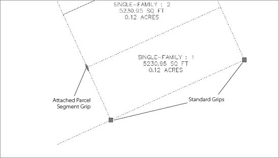
Parcels created from objects, such as the boundary and internal segments will have standard grips, like a polyline. These grips can be used just as you would expect—you can drag and move your parcel boundary as necessary. Segments created using Parcel Layout tools, such as Free Form Create and Slide Angle Create, will have a special diamond-shaped grip that can slide along the frontage and will respect the original angle setting, as shown in Figure 6.20.
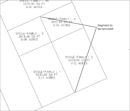
You will want to remove segments to make some parcels larger, refine their shape, or perhaps go through more iterations with the automatic layout tools.
For example, say you have four lots that share a common internal segment, as in Figure 6.21.
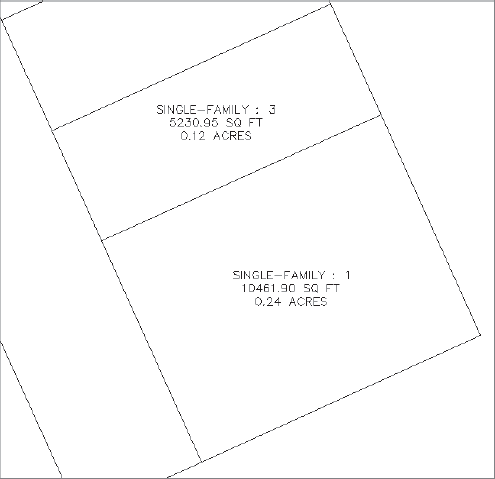
If you use the AutoCAD Erase command, the entire length will be removed, and two parcels will remain, as shown in Figure 6.22.
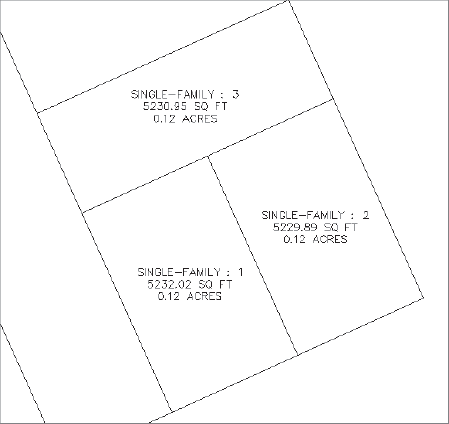
The Parcel Layout Tools dialog also has a Delete Sub-entity button. Clicking this button will delete the length of the segment between other parcel segments, as shown in Figure 6.23.
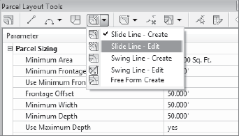
You can also make intelligent edits to attached parcel segments using the Slide Angle, Slide Direction, and Swing Line Edit tools from the Parcel Layout Tools dialog (shown in Figure 6.24). These commands will lead you through making changes to an angle, area, and more.
If there are no automatic tools to fit your design intent, you can always draw AutoCAD linework to convert to parcel segments or use Free Form Create. Just be sure to trim or extend your linework as necessary before converting it to a parcel segment. This is especially useful when capping off the rear lot lines so that they are straight instead of curved, creating segments with odd angles, or adding open space, wetlands parcels, or utility lots. An example of a finished lot created from AutoCAD linework is shown in Figure 6.25.
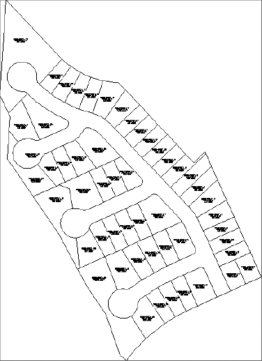
Using the previous editing techniques and all of the tools shown in this chapter, work through the rest of the site so that you get a feel for creating parcels in a real-world situation. One possibility for a final design is shown in Figure 6.26.
In this chapter, you were introduced to some of the many tools available for working with parcels. Parcels are incredibly powerful tools that provide ways to automatically label areas and segment information, and to stylize linework. Most importantly, parcels give you the power to go through many more design iterations in far less time, which will lead to better-quality site plans that truly meet your design intent and form the foundation for better neighborhoods everywhere.