
For thousands of years, engineers have laid out plans for construction. From the aqueducts of Rome to the Big Dig project in Boston, construction projects have been shown as flat lines on paper illustrating some horizontal placement of the project being designed. In Civil 3D, this planar element of the design is handled by the Alignments feature.
You can use alignments in Civil 3D to determine road centerlines, pipe layouts, curb returns, parking island curbs, pond berms, and any number of things where you've used a polyline in the past. The ability to use the vertical design elements of feature lines, profiles, and corridor design make alignments an integral part of the process like never before. Combined with the ability to reference across drawings and use the benefits of dynamic labeling, alignments are an important tool in the Civil 3D user arsenal.
This chapter includes the following topics:
Converting polylines to alignments
Drawing simple alignments by layout
Editing alignments with grips and tabular tools
Labeling station and geometry data with alignment label sets
Labeling critical plan points using station-offset labels
The horizontal control of an alignment has some benefits beyond the simple geometry and labeling. The main benefit is that the alignment object has the ability to understand the whole piece instead of just being individual arcs and lines tied together. Alignments can be constructed with relationships between the adjoining segments, so that a change in the properties of an arc changes the length of a line tied to it or the direction of a spiral segment. These powerful relationships are known as fixed, float, and free.
Fixed entities are independent of other segments in the alignment, fixed to the coordinate plane. A fixed entity is typically a line based on a start point and distance and bearing, or an arc based on three known points. This type of segment will not maintain tangency if the segments on either side are moved or edited.
Float entities have some measure of independence but are tied to one other segment in a tangential relationship. This can be a line extending from the end of an arc in a tangent direction for a given distance, or an arc coming from a line and passing through a given point. If the attachment entity is edited in some way, a floating entity will adjust to maintain tangency if at all possible.
Free entities are dependent on the segments before and after for their location. Think of a fillet curve between two line pieces, or a tangent connecting two curves in an S-shape. These segments will adjust and change as required to maintain the tangency on both connection points.
There are two main methods of creating alignments: converting from polylines and creating from scratch, known as creating by layout. In the next sections, you'll practice using both methods.
For many users of Civil 3D, it's easiest to learn the conversion method and then work into the layout method as familiarity with the layout toolset increases. There are some gotchas with using the polyline method of creation, but as long as you are aware of them, you can plan in advance and handle them easily. In this exercise, you'll convert a number of polylines to alignments using different settings and options to understand the options involved.
Open the
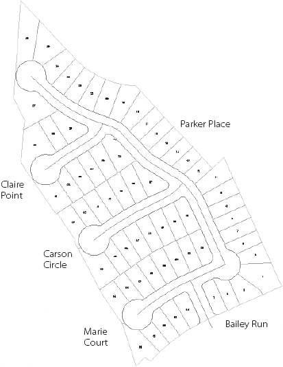
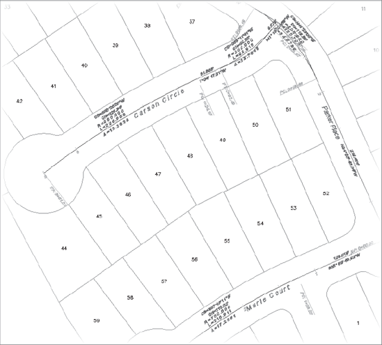
Converting Alignments.dwgfile. (Remember, all the data for this book can be downloaded fromwww.sybex.com/introducingcivil3d2010.) Figure 8.1 shows the layout and the street names you'll be referring to in this series of exercises.From the Home tab's Create Design panel, select Alignment → Create Alignment from Objects.
Select the polyline representing Parker Place somewhere near the southern end. At the
Select lines/arcs or polylines to create alignment:prompt, press Enter.Notice the arrow graphic on the screen showing you the direction of the alignment. Note that you can reverse the direction of the alignment by typing R for Reverse. At the
Press enter to accept alignment direction or [Reverse]:prompt, press Enter to accept the alignment direction. The Create Alignment from Objects dialog appears (see Figure 8.2).In the Name area, enter Parker Place, but leave the rest of the options alone so your dialog looks like Figure 8.2.
Click OK to dismiss the dialog.
Congratulations, you've made your first Civil 3D alignment! Now, let's look back at Figure 8.2 and discuss the options skipped over so rapidly in the exercise.
The Name and Description fields should be fairly self-explanatory. Descriptions become more important as you begin modeling complex sites and have more alignments to manage. The Description field can be displayed as part of a label, so sometimes it can be used for ancillary information such as road type, channel lining, or other information that could be accessed handily.
The Type field is new to Civil 3D 2010. It allows you to further group your alignments. The type options are Centerline, Offset, Curb Return, and Miscellaneous. The Centerline option might be used for any type of centerlines, whether they are road or stream. The Offset option might be used for a stakeout of Building Setback lines. The Offset Curb option might be used for curb returns in an intersection. The Miscellaneous option can be used if none of the other categories fit your design. Note that you do not have to use these options explicitly for centerlines, offsets, or curb returns. They are merely provided to assist you with grouping similar alignments.
The Starting Station field allows you to set the beginning station of the alignment to be created. Most users will leave this value at 0+00, but many sewer systems are laid out with 1+00 as the starting point to allow for some modifications later without a change in the stationing through the line.
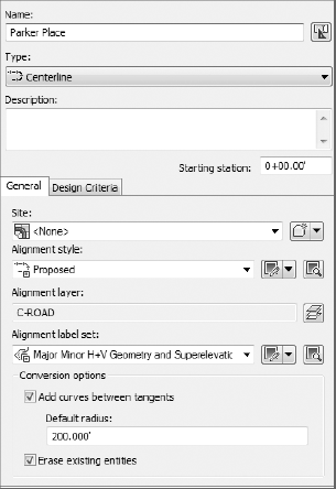
There are two tabs on the Create Alignment dialog: General and Design Criteria. The General tab handles alignment properties that are general to all alignments, and the Design Criteria tab is focused on transportation- and infrastructure-based uses.
The General tab includes the following settings:
The Site setting controls which Civil 3D site an alignment will be contained within. You can refer to Chapter 6, "Parcels," for a full explanation of the Civil 3D sites, but most alignments are best stored in the <None> site as shown in Figure 8.2.
Alignment Style controls the display of the actual alignment object in Plan, Model, and Section views. This style also controls the appearance of any markers at the beginning, end, or intermittent geometry points along the alignment.
Alignment Layer controls what layer the alignment object itself will be placed on. If you think of alignments as nested blocks, it's easier. The object will reside on this layer, but the subcomponents (lines, arc, spirals, and so on) will be display-controlled by the style settings.
An alignment label set is a collection of label styles that are applied to an alignment at creation. These can include labels at the beginning and end, at PC or PT points, and at vertical data points such as a High Point or a Superelevation Critical point.
The Add Curves Between Tangents option enables you to add filleted arcs between lines when the polyline has not had arcs placed in it. These arcs are free arcs per the preceding definition, dependent on the tangent lines before and after for their location.
Erase Existing Entities simply erases the polyline being converted from the drawing when the conversion is complete.
On the Design Criteria tab, there are essentially two options in play: Criteria-Based Design and Design Check Sets. Criteria-Based Design takes the user input of a design speed, compares it with a design criteria file based on AASHTO 2001 specifications, and sets some design parameters for the alignment to be created. Design Check Sets allow you to specify design values, such as Minimum Radius or Minimum Tangent Length, and will warn you when these values are violated. Again, this tab is focused heavily on the large transportation market, and many Civil 3D users are happy to ignore it entirely.
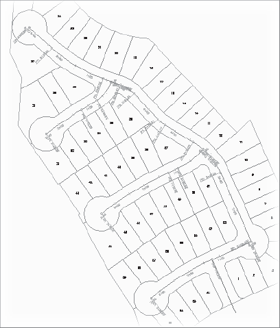
To practice this conversion method a few more times, convert the three other major streets in the subdivision using the same commands and settings. Be sure to change the names as previously shown in Figure 8.1. It does not necessarily matter which is your starting point (you can change this later), but for the purposes of this example, the start of each alignment is tied into the Parker Place alignment. When you're done, your drawing should look something like Figure 8.3.
After polylines have been converted to alignments, the segments in the alignment have relationships based on the way the polyline was originally created. In some cases, this means that editing an individual segment or grip breaks the tangency as shown in Figure 8.4.
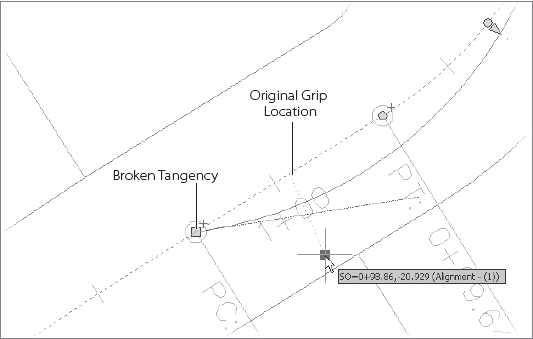
Experiment with this by selecting the new alignments and grip editing. You will look at editing in a later section, but it's important to note that this quirk of the conversion process is one reason many people advocate simply redrawing alignments using the method in the next section.
When creating alignments by layout, there are many more options to consider. Spirals cannot be drawn at all with polylines, and laying out an alignment piece by piece gives you the ability to control and drive the tangencies of your design. In this first exercise, you'll create the simplest alignment, using typical Point of Intersection (PI)–based design with curves filleted in between the tangents.
Open the
Layout Alignments.dwgfile. This is the same site as in the prior section; the street is drawn without any arcs so that finding PIs is easier.From the Home tab's Create Design panel, select Alignment → Alignment Creation Tools.
Change the name to Parker Place, but leave the other options as they are.
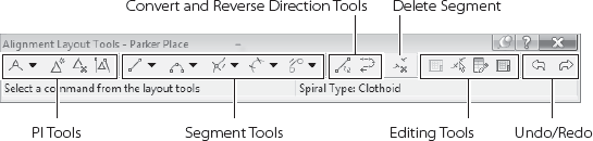
Click OK and the Alignment Layout Tools toolbar will appear. This toolbar is divided into six sections, as shown in Figure 8.5.
Most users work from left to right across this toolbar. The basic tools for creation are on the left. The PI tools are designed to work with the most basic method of laying out an alignment, working from PI to PI with curves optionally inserted based on a radius, and with or without spirals in and out. The Segment tools allow the user to place individual lines, arcs, and spiral segments, tying them together with the tangent relationships as appropriate. The Conversion tools are handy for converting existing linework into segments, and the Delete Segment tool will remove a single piece of an alignment without erasing the whole object. Finally, the Edit tools allow for detailed, grid-based editing of the alignment components.
Now that you're familiar with the toolbar, you'll make a simple, PI-based alignment.
Click the drop-down arrow on the far-left button and select Tangent – Tangent (with Curves) to begin the layout process.
Use an endpoint osnap, and click the southern end of the polyline that describes Parker Place.
Use an end osnap and click the first PI to the north. A jig will appear showing where the next tangent will be created, as in Figure 8.6. Also, if there is enough room as you move your cursor about, you will see a blue arc indicating the curve that Civil 3D will place in the alignment based on your settings.
Use an end osnap and click the successive PIs, working your way to the north end of the cul-de-sac.
After selecting the last point, right-click to exit the command and your alignment will be complete.
The curves created by the program are based on a simple fillet with a given radius. You can set this radius by clicking the same drop-down arrow within the Alignment Layout Tools toolbar and selecting Curve and Spiral Settings. The dialog that appears in this case allows you to set the radius of the fillet curves, along with turning on and off spiral in and out options.
Now that you've created a basic alignment using simple fillets, you'll explore a basic alignment with a fixed and floating component in this next exercise.
Within the same
Layout Alignments.dwgfile, select Alignment → Alignment Creation Tools from the Home tab and Create Design panel on the ribbon to display the Create Alignment-Layout dialog.Change the Name to Marie Court, and then click OK to close the dialog.
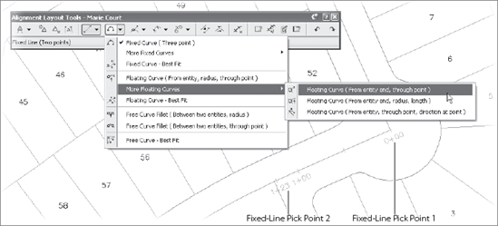
On the Alignment Layout toolbar, click the Fixed Line (Two Points) button.
Click the endpoint of Parker Place alignment to begin, and then snap to the end of the tangent line heading west.
Right-click to exit the Fixed Line command. Your screen should look like Figure 8.7. Before you do the next step, send the polyline to the back so that the alignment is on top.
On the toolbar, select the Floating Curve (From Entity End, Through Point) command as shown in Figure 8.7.
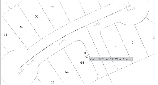
Using the endpoint osnap, click on the end of the polyline at the bulb of the cul-de-sac, and then right-click to exit the curve command. Your alignment should look like Figure 8.8. Notice that the tooltip on the cursor also reflects the stationing of this new alignment.
Click the X on the Alignment Layout Tools toolbar to close it.
Select the Marie Court alignment to activate the grips. Make sure to pick an alignment segments, not the labels!
Select the easternmost grip, where Marie Court and Parker Place intersect, and drag it away. Notice how the curve portion continues to maintain both tangency and the end point in the cul-de-sac as shown in Figure 8.9.
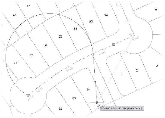
The ability to create and maintain relationships between pieces of your alignments means you can rest easier knowing that your streets are always in tangent, your channels always flow smoothly, and your sidewalks meander gracefully throughout their lengths. Now that you've explored creating alignments, you'll look at grip and tabular editing in the next section.
One of the catchphrases used when describing the work process with Civil 3D is, "Design then Refine." The idea here is that your design does not have to be set in stone before you can begin using the ideas and information you have. As you've seen, it's pick-and-click simple to make a basic road alignment from polylines or from parameters, designing by simply picking points on the screen and letting Civil 3D handle the fitting and labeling. In this section, you'll look at the refine part of the phrase. You'll learn how to use both grip and tabular editors to modify alignments.
Grip editing is a part of every AutoCAD user's toolbox, allowing for quick and easy edits. This process is no different with Civil 3D alignments, except that some grip edits can't be done based on the relationships between segments. In those cases, Civil 3D simply won't allow you to make the change, reverting to the initial position. In this exercise, you perform a basic grip edit.
Open the
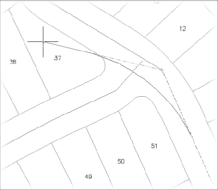
Editing Alignments.dwgfile. This is basically the same site you used in earlier exercises; however, some more alignments have been created, and some have been inadvertently modified. Zoom in on the northern cul-de-sac on the Parker Place alignment and notice that it no longer follows the road centerline sketched in with a line.Select the alignment to activate its grips.
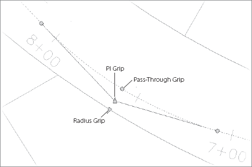
Select the triangle grip pointing vertically to select the PI point of the alignment. The triangle pointing radially near the same point is the radius grip for the curve. Figure 8.10 shows the grips with short descriptions. Note that the three pass-through grips on the arc simply change the radius to meet a new pass-through point.
Using an end osnap, move the PI to the southern end of the sketched line. Civil 3D will update the alignment, curve, and stationing for you.
This basic grip edit will solve a large number of problems for you. You can also now experiment with various alignments of your object to handle different scenarios. When you're trying to avoid a large specimen tree in a site design, or flirting with the edge of a wetlands area, being able to quickly iterate through options and knowing that your curves and labeling are all intact make the process much less daunting. If you want to experiment some more, use a center snap to fix the Claire Point western arc, which is out of place. Grips work well for approximate work, but for fine-tuning you might need to modify parameters. You'll explore that next.
Sometimes you need a higher level of control within the design. Grip edits are good for placement, but there's no easy way to grip edit the radius on a curve. For this process, Civil 3D offers two main methods of data editing: the Component Editor and the Panorama Editor. You'll use both in this exercise, and you can decide which is better for your everyday toolset.
Still using the
Editing Alignments.dwgfile, select the Parker Place alignment to activate it. Notice that the contextual ribbon shows only information pertaining to the Parker Place Alignment.From the Modify panel, select Geometry Editor. You can also right-click and select Edit Alignment Geometry from the context menu to display the Alignment Layout toolbar. Refer back to Figure 8.5, and you'll see that the right third of this toolbar is all about editing.
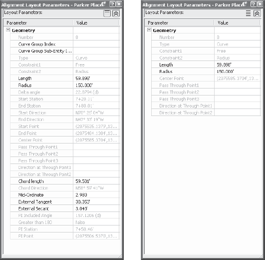
Click the Pick Sub-Entity button, and the Alignment Layout Parameters palette shown in Figure 8.11 will appear. Figure 8.11 shows two versions of the same dialog. Note the button in the upper right with multiple horizontal lines. This is the Show Less/More toggle that will alter the amount of information shown in the palette. Set your toggle to Show Less.
Click the arc segment of the alignment near station 7+50 to populate the data as in Figure 8.11.
Click the Radius cell to highlight the 150′ value. Enter a new value of 200′ and press Enter. The curve immediately reflects the change.
Close the Alignment Layout Parameters palette using the red X in the upper-right corner and press Esc to exit the command.
Note that you can also use this palette to copy values to another program such as Excel by right-clicking in the empty space within the palette and selecting Copy to Clipboard. Editing values one at a time is tedious though, so in this exercise, you'll use Panorama to display the entire alignment in a tabular format.
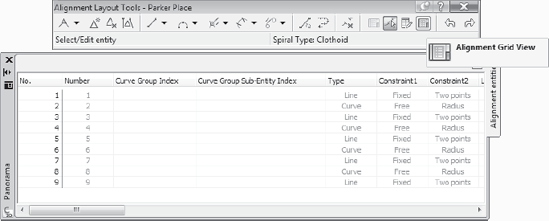
On the Alignment Layout Tools toolbar, click the Alignment Grid View as shown in Figure 8.12 to display Panorama with an Alignment Entities tab active. Note that black values are editable, and gray values are derived values, so they cannot be modified.
Click the Radius cell for any of the curves and change the value to 200′. Repeat this for all of the curve entities. As mentioned in Chapter 1, "Welcome to the Civil 3D Environment," the columns in this view can be rearranged and resized as necessary.
Close Panorama by clicking the X, or by clicking the Alignment Grid View in the Alignment Layout Tools toolbar again.
Close the Alignment Layout Tools toolbar to complete your edits.
By using the Component Editor and the grid view in conjunction, editing to precise values for curves, spirals, and lines can be accomplished simply and quickly. Once your alignment is in place, labeling becomes a critical task.
Unlike many design applications, the labels in Civil 3D are inherently tied to the objects they label. This means that the changes and edits you explored previously are all reflected in the alignment labeling. In this section, you'll learn about the three major label types related to alignments: stationing, segment, and station-offset. Each of these is dependent on a myriad of styles, but you'll focus more on the use of these labels in the following exercises as opposed to building a bunch of label styles.
Almost every designer has stationed a road or pipeline. With Civil 3D, stationing refers not only to the station values, but also to other labels that are dependent on the alignment (and associated profile) geometry. The options for labeling points in an alignment are as follows:
Major Station
Minor Station
Geometry Point
Profile Geometry Point
Station Equation
Design Speed
Superelevation Critical Points
Each of these label options is driven by a style, and the whole process can seem a bit overwhelming. Remember, 75 percent of the time, you'll be labeling alignments in exactly the same way, and to that end, you'll have label sets that pull together all of the options. In this exercise, you'll explore changing individual labels and then creating and using a label set.
Open the
Stationing Alignments.dwgfile.Select the Carson Circle alignment to activate it. The alignment labels have been removed for this exercise.
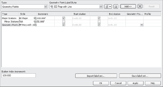
From the Carson Circle Alignment contextual ribbon and the Labels & Tables panel, select Add Labels → Add/Edit Station Labels. You can also right-click and select Edit Alignment Labels from the pop-up menu. The Alignment Labels dialog is displayed as shown in Figure 8.13.
Select EE Major on the Major Station Label Style drop-down list, and then click the Add>> button to add that label to the alignment.
Select Minor Stations on the Type drop-down list.
Select Tick from the Minor Station Label Style drop-down list, and then click Add>>.
Select Geometry Points from the Type drop-down list.
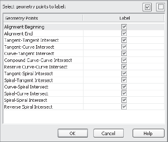
Select EE Perp with Line from the Geometry Point Label Style drop-down list, and then click Add>> one more time. This time, the Geometry Points dialog in Figure 8.14 will appear.
This dialog lets you apply different label styles to different geometry point types if desired. Leave them all turned on for now and click OK to dismiss the dialog. Your Alignment Labels dialog should look like Figure 8.13 now.
Click OK to dismiss the dialog and update the Carson Circle alignment.
The station is labeled, but you do have to take care of a few minor clean up issues. Individual labels aren't editable unless you use Ctrl+click to pick them. To finish this exercise, you'll remove the Station labels at the beginning and end of the alignment because you already have geometry labels at those points.
Press Esc to make sure no objects are selected in Civil 3D.
Ctrl+click the 3 label at the end of the Carson Circle alignment. This is a major station label that you don't want to see. Note that this selection picks only the individual label, not the full range of major station labels as a typical click would.
Press the Delete key on your keyboard (not the Backspace key) to erase the single label from your drawing.
Repeat the process on the 0 at the beginning of the alignment.
It's worth noting that the BP and EP abbreviations used in the beginning and ending labels are abbreviations picked up from the drawing settings. Revisit Chapter 1 if you'd like to see how you can go about making those changes. Also, if you delete an individual label but then decide you want it back, select one of the other major station labels, right-click, and select Reset All Group Labels.
Although this process isn't overly long for a simple setup, it still could be tedious to remove all the labels and reapply the new ones based on your desired settings. To that end, you'll create a label set in this exercise and apply it to another alignment.
Select the Carson Circle alignment again.
From the Carson Circle Alignment contextual ribbon and the Labels & Tables panel, select Add Labels → Add/Edit Station Labels. You can also right-click and select Edit Alignments Labels to display the Alignment Labels dialog.
Click the Save Label Set button near the lower right to display the Alignment Label Set dialog. This dialog is the same as the individual Alignment Labels dialog in that you can pick labels types and styles to build up a collection of typical labels.
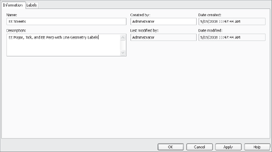
Change to the Information tab in the dialog.
Click in the Name field and enter EE Streets as a name. You can enter a description as shown in Figure 8.15 if you like. Descriptions make it easier to pick a label set later when you're trying to remember what labels are in each set.
Click the OK button to dismiss this dialog, and click OK again to close the Alignment Labels dialog.
Press Esc to make sure no objects are selected in Civil 3D, and then select one of the other alignments.
From the contextual ribbon and the Labels & Tables panel, select Add Labels → Add/Edit Station Labels. You can also right-click and select Edit Alignment Labels to display the Alignment Labels dialog.
Click the Import Label Set button on the lower right to display the Select Style Set dialog.
Select the EE Streets option from the drop-down list. Note the description entered previously is displayed here to make selection easier.
Click OK to close the dialog, and click OK again to return to the drawing window. You have replicated the labeling from Carson Circle in just a few clicks.
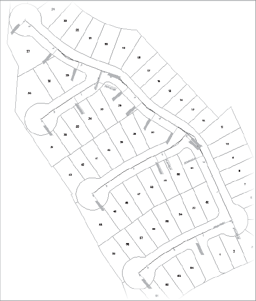
Repeat this process on the other two alignments. When complete, your drawing should look similar to Figure 8.16.
You will need to make the same edits to the beginning and ending station labels, but in general, using a label set is a fast and easy way of making a whole host of alignments look as desired. Now that the stationing is handled, it's time to explore segment labels.
It's a common requirement that labels on alignments assist in the layout of the alignment geometry in the field. To that end, individual segments can be labeled with the necessary information such as distance and bearing, or chord bearing, radius, and other curve information. Many Civil 3D users also use segment labels to place street names in their drawings. You'll do both in this exercise.
Open the
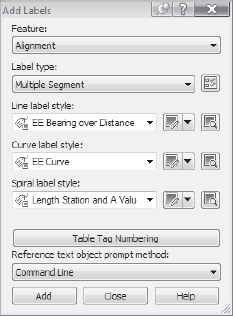
Labeling Alignments.dwgfile.From the Annotate tab's Labels & Tables panel, select Add Labels → Alignment → Add Alignment Labels to display the Add Labels dialog shown in Figure 8.17.
Change the Label Type drop-down list to Multiple Segment.
Change the Line Label Style drop-down list to EE Bearing over Distance.
Change the Curve Label Style to EE Curve. Your dialog should now look like Figure 8.17.
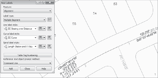
Click Add and select the Marie Court Alignment to apply your labels. If you zoom in on the alignment, your drawing will look something like Figure 8.18.
The command is still active, so pick each of your alignments to label them as you've configured in this dialog.
Move back to the Add Labels dialog and change the Label Type drop-down list to Single Segment.
Change the Line Label Style and the Curve Label Style to EE Street Name. Both of these label styles simply add the Alignment name, but you do have to set up both so that you are not limited to only putting the street name label along tangent segments.
Click Add, and then zoom in on the Marie Court alignment again.
Click the alignment near the 2+00 station to place the street name label, and then repeat this on the other alignments at suitable locations. Your drawing should look something like Figure 8.19.
Right-click to exit the command, and then close the Add Labels dialog by clicking the Close button.
The first pass of labeling often creates a number of conflicts. Clicking any label will reveal two grips. Moving the square grip will move the label to a more suitable location and make the plan more readable. Also, with a single label selected, the right-click menu will offer the option to flip the label. Experiment with dragging and flipping to clear up any labeling conflicts. With the alignments labeled as needed, it's time to look at labeling some property lines with station-offset labels.
The last major type of label in the alignment family is a station-offset label. Some examples of these labels are calling out curb returns, the locations of curb inlets, and street lights, or for placing trees along a path. In the following exercise, you'll use station-offset labels to mark curve points along the street right-of-way.
Open the
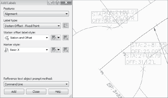
Offset Labels.dwgfile.From the Annotate tab and Labels & Tables panel on the ribbon, select Add Labels → Alignments → Add Alignment Labels to display the Add Labels dialog.
Change the Station Offset Label Style drop-down list to Station and Offset.
Change the Marker Style to Basic X.
Click Add, and Civil 3D will prompt you at the command line to select an alignment.
Pick the Marie Court alignment to activate it.
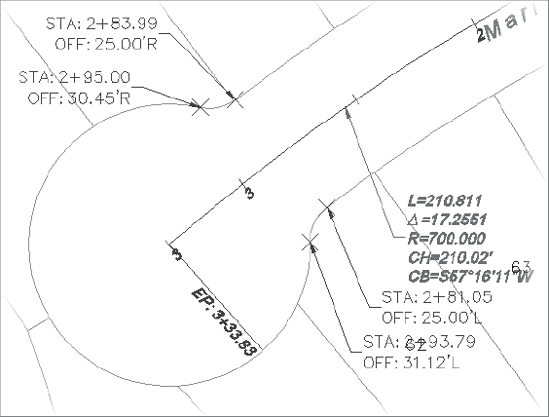
Using an end osnap, select the ends of the three arcs that make up the cul-de-sac area. When complete, your drawing should look like Figure 8.20.
Click Close on the Add Labels dialog to close it.
Select any of the labels just created, and you will be presented with two grips. One is to slide the label moving the point being labeled as well, the other is to drag the label moving only the text. Pause near each grip and a tooltip will be displayed to help in selecting the correct grip for your intended use.
Drag the four labels to make the labeling clearer, and your drawing will look something like Figure 8.21.
Although a simple station offset is useful, it's important to note that more complex labeling can be accomplished within all of the labels throughout Civil 3D. In this exercise, you'll label a point in space based on two different alignments to understand how that point relates to each.
Pan your drawing so the intersection of the Parker Place and Marie Court alignments is on your screen. The exercise is to label the imaginary point in space where the right-of-way lines would intersect.
From the Annotate tab and Labels & Tables panel on the ribbon, select Add Labels → Alignment → Add Alignment Labels to display the Add Labels dialog.
Change the Station Offset Label Style to EE Intersection.
Change the Marker Style to Basic Circle with Cross, and then click Add.
Select the Marie Court alignment.
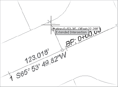
Use an intersection osnap, but pick the line on the front of lot 52 as shown in Figure 8.22. Note the ellipsis on the glyph—this indicates an extended intersection, allowing you to pick an imaginary intersection instead of a real one.
Move your cursor over the side lot line of lot 52 and notice the glyph jumps to the point in space where the two lines would cross. Civil 3D will prompt for a Crossing Street at the command line. You could also use the Apparent intersection osnap.
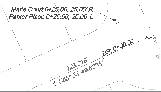
Pick the Parker Place alignment to complete the label.
Drag the label to a more suitable location as shown in Figure 8.23, and then click Close on the Add labels dialog to dismiss it.
This particular label style was built just for labeling plan data, but information can be pulled from profiles as well. The ability to label points in space can be incredibly useful during the design stage to help verify that your geometry is set up correctly and that your vertical design will come together without large leaps between intersecting streets.
Because of its power to maintain geometric relationships, the alignment object in Civil 3D is used for more than just roads. Creating alignments is easily done by converting from existing linework in the form of polylines or by laying out completely new objects. Manipulation of these design elements while adhering to rules about tangency makes the exploration of design alternatives easier than ever.
Labeling functions are straightforward but powerful. By tying to the object instead of simply creating text in the drawing file, Civil 3D makes the tedious tasks of updating stationing, street names, or offset calls a thing of the past. Additionally, the use of label sets makes it easy to standardize how labels appear across a set of plans or within a firm, making standards adherence more straightforward. Finally, by using dynamic labeling for both plan production and design purposes, you can reduce errors and review problems.