
In land development project design, roads follow one or more typical sections. These typical lane, curb, and sidewalk configurations are usually based on standards put forth by the governing body, such as a state department of transportation or local municipality. Civil 3D provides tools to model these typical sections as assemblies. Once the assembly is created, it is combined with alignments and profiles to create a corridor model.
This chapter includes the following topics:
Importing a standard assembly
Customizing lane width in a standard assembly
Building a road corridor from an alignment, a profile, and an assembly
Viewing corridor sections
Building a finished ground surface from a corridor
Observing the dynamic reaction of the corridor model
Civil 3D includes a robust catalog of road components for building any imaginable typical section as an assembly. In addition to simple lanes, curbs, and sidewalks, the catalog also includes parts for rehabilitation projects, superelevation, and channels, among other options. These parts come preloaded onto several Tool palettes so that they are at your fingertips when you begin building your model. In addition to the smaller components, called subassemblies, there are several prebuilt standard assemblies for basic roads, divided highways, intersections, and roundabouts (see Figure 10.1).
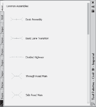
Figure 10.1. Civil 3D comes with several prebuilt typical assemblies. This image shows five typical road assemblies. There are also assemblies for intersections and roundabouts.
In the following exercise, you'll bring in one of these assemblies, which you'll later customize.
Open the drawing file
Corridors1.dwg, which you can download fromwww.sybex.com/go/introducingcivil3d2010.From the Home tab and Palettes panel on the ribbon, select the Tool Palettes icon. The Tool palettes will appear.
On the Tool palettes, switch to the Assemblies – Imperial Tool palette, as shown in Figure 10.1.
Click the Through Road Main assembly. The AutoCAD Properties palette will appear.
At the
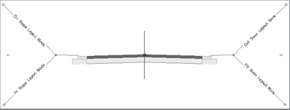
Specify Location for Assembly:prompt, pan over to the right of the site, below the profile, and select any location where there is room to work. An assembly will appear in the drawing. Press Esc to exit the command and dismiss Panorama. The assembly will look like Figure 10.2.Save the drawing—you will need it for the next exercise.
The prebuilt assemblies are excellent for getting started, but they are rarely a perfect fit to the required design. Sometimes, only small changes are necessary, such as lane width or curb height, while other times you may have to build an assembly from scratch using the catalog subassemblies. For this example, you will change the lane width parameter and lane slope parameter to customize the assembly.
Select the assembly by clicking the vertical red line. From the contextual ribbon and the Modify Assembly panel, choose Assembly Properties. The Assembly Properties dialog will appear.
Switch to the Construction tab of the Assembly Properties dialog.
Select the Lane entry under Through Road Main – Right. Information about this lane will appear on the right side of the dialog under Input Values.
Change the Width entry from 13.5′ to 10′, as shown in Figure 10.3.
Change the Default Slope entry from −2.00% to −3.00%.
Repeat steps 1 through 5 for Through Road Main – Left.
Click OK to exit the dialog. The slope and width of each lane has been changed.
Save the drawing—you will need it for the next exercise.

Once the typical section has been built as an assembly, it can be combined with an alignment and profile to build a corridor model. A corridor takes the horizontal design of the alignment combined with the vertical design of the profile and the cross-sectional aspect of the assembly and combines them into one three-dimensional model.
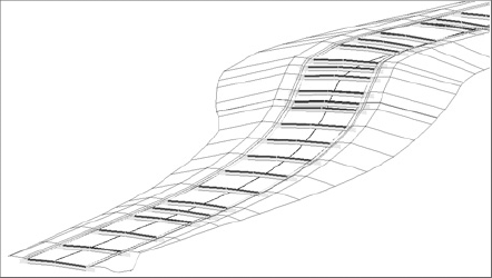
Figure 10.4 shows the corridor from this chapter in an isometric view. Note how each assembly is applied along the proposed alignment, and vertical rise can be observed, which comes from the design profile.
The following exercise will give you hands-on experience building a corridor model from an alignment, a profile, and an assembly.
Continue working in
Corridors1.dwg.From the Home tab and the Create Design panel on the ribbon, choose Corridor → Create Simple Corridor. The Create Simple Corridor dialog will appear.
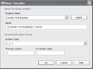
If you knew the name of the design alignment, you could type it by hand, but it would be better to have Civil 3D read the name of the alignment and automatically build it into the corridor name with a name template. Once a name template is created, all new corridors will be automatically named to your specifications.

Delete the information in the Name field.
Use the Property Fields pull-down list to select Corridor First Baseline. Click the Insert button. The Name field will now be populated with <[Corridor First Baseline]>, which is a special formula that will read the name of the alignment you choose as your first baseline.
In the Name field, type a space followed by the word Corridor to the right of the <[Corridor First Baseline]> formula, as shown in Figure 10.5.
Click OK to dismiss the Name Template dialog. The Create Simple Corridor dialog will return. Click OK.
This named your corridor using a name template. The resulting corridor will appear in Prospector with the name Parker Place Corridor.
At the
Select a baseline alignment <or press enter key to select from list>:prompt, press Enter. The Select an Alignment dialog will appear. Select Parker Place, and then click OK.At the
Select a profile <or press enter key to select from list>:prompt, press Enter. The Select a Profile dialog will appear. Use the Select a Profile drop-down list to select Parker Place FG. Click OK.At the
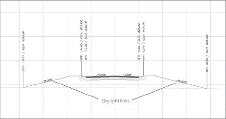
Select an assembly <or press enter key to select from list>:prompt, press Enter. The Select an Assembly dialog will appear. Use the drop-down list to select Through Road Main. Click OK.The Through Road Main assembly includes a daylight subassembly called BasicSideSlopeCutDitch, as shown in Figure 10.6.
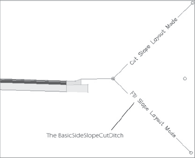
Figure 10.6. The BasicSideSlopeCutDitch assembly provides information to the corridor about how to connect with existing ground, including adding a ditch in the cut condition.
A daylight subassembly gives the corridor information about how the designer wants to tie into existing ground, as shown in Figure 10.7. The BasicSideSlopeCutDitch has parameters for both cut and fill, including adding a ditch when a section is in an area of cut.
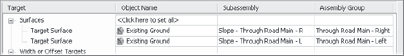
Before the daylight subassembly can do its work, you must select which surface will act as the existing ground, or target surface. After completing step 10, the Target Mapping dialog will appear to prompt you to choose a surface.
The Target Mapping dialog will appear. Click inside the Surfaces field that says <Click here to set all>. The Pick a Surface dialog will appear. Choose Existing Ground, and then click OK. A surface is now assigned to both sides of the road for daylight calculations, as shown in Figure 10.8
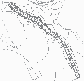
Click OK to exit the Target Mapping dialog. The corridor will build, and the message
Corridor 'Parker Place Corridor' createdwill appear in the command line. The corridor will appear in the drawing, as shown in Figure 10.9.Save the drawing—you will need it for the next exercise.
Once a corridor model has been created, you will often want to explore each section quickly to get a feel for what has been built and make notes of what needs to be changed with the design, adjusted, or modeled differently. An easy way to view each section is by using the View/Edit Corridor Surfaces tool. The following exercise will lead you through exploring your corridor model with this tool.
Continue working in
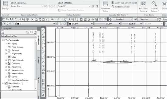
Corridors1.dwg.Select the Corridor object in the drawing. From the Corridor contextual tab and the Modify panel, choose Corridor Section Editor. The View/Edit Corridor Section Tools dialog will appear, as shown in Figure 10.10

Use the Select Station pull-down list to advance to station 5+50.00. Note that the BasicSideSlopeCutDitch subassembly has made a ditch for this section because the profile drives this section into cut.
Use the Select Station pull-down list to advance to station 7+00. Note that the BasicSideSlopeCutDitch subassembly has used the 50 percent slope to connect to existing ground because the profile drives this section into fill.
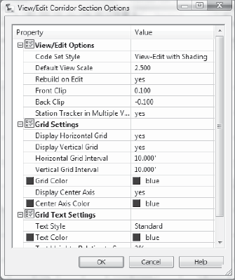
From the Corridor Edit Tools panel on the contextual ribbon, select Edit/View Options. The View/Edit Corridor Section Options dialog will appear, as shown in Figure 10.11.
Click in the Code Set Style field until you see an ellipsis button. Click the ellipsis button. The Code Set Style dialog will appear.
Use the pull-down to change the Code Set Style from View-Edit with Shading to View-Edit. Press OK to exit the dialog.
Click OK to exit the View/Edit Corridor Section Options dialog. Note that the assembly shading disappears.
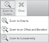
Click the Zoom to a Subassembly button as shown in Figure 10.12. The Pick Subassembly dialog will appear. Use the pull-down list on the Pick Subassembly dialog to select Curb – Through Road Main – L and click OK. The view will zoom in on the curb subassembly.
Explore some of the other tools on the View/Edit Corridor Section Tools dialog. Observe what happens when using the wheel mouse pan and zoom features.
Press Esc to exit the command. Explore the corridor by toggling through additional stations. When you're done exploring, click the X on the contextual ribbon to exit the View/Edit Corridor Section Tools dialog.
Save the drawing—you will need it in the next exercise.
A corridor is a complete road model that can be used to build one of many surfaces. Surfaces are commonly built to represent the final finished grade (top surface) or to represent subgrade (datum surface). The following exercise will give you experience building a surface from the pieces of the corridor that represent a final finished grade.
Continue working in
Corridors1.dwg.Select the corridor in the drawing. From the corridor contextual ribbon and the Modify panel, choose Corridor Properties. The Corridor Properties dialog will appear.
Switch to the Surfaces tab of the Corridor Properties dialog.

Confirm that the Data Type is set to Links and Specify Code is set to Top.

Click OK.
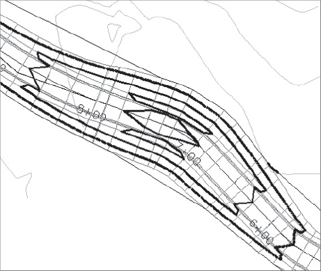
Zoom in on your corridor to see the contours from the corridor surface, as shown in Figure 10.13. You may have to rebuild the surface in order to view the contours.
Every good surface should have a boundary. Boundaries clean up bad triangulation around the edges of a surface and are critical for corridor surfaces because bends in the road can encourage improper triangulation. For single-baseline corridors—that is, corridors that are built using one alignment—there is an automatic boundary feature.
Select the corridor in the drawing. From the contextual tab and the Modify panel, choose Corridor Properties. The Corridor Properties dialog will appear.
Switch to the Boundaries tab of the Corridor Properties dialog.
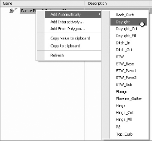
Right-click the Parker Place Corridor Surface – (1) surface entry and use the Add Automatically fly-out menu to select Daylight as shown in Figure 10.14.
Click OK.
Zoom and pan around the corridor. Notice that the surface has been constrained to the outermost corridor feature line, which is the piece of the corridor that represents the daylight connection with existing ground.
Save your drawing—you will use it in the next exercise.
Now that you understand how a corridor is constructed, it is important to see how this model will react as your design evolves. It is not necessary to have your alignment, profile, or assembly design perfected before you model the road, because the corridor will update as you design and help you understand how your design is evolving.
The following exercise will lead you through making design changes to the profile and a lane width so that you can see how a corridor reacts dynamically.
Continue working in
Corridors1.dwg.Locate the Prospector tab of the Toolspace. Expand the Corridors entry. Right-click Parker Place Corridor and choose Rebuild – Automatic.
Still on the Prospector tab, expand the Surfaces entry. Right-click Parker Place Corridor Surface and select Rebuild – Automatic (if it is not already selected).
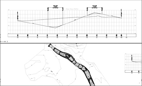
From the View tab and the Viewports panel on the ribbon, Choose Viewport Configurations → Two: Horizontal. The view will be split into two ports, as shown in Figure 10.15
Click inside the top viewport to activate it. Zoom in on the profile view.
Click inside the bottom viewport to activate it. Zoom in on the road.
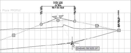
Click inside the top viewport to activate it. Select the finished ground profile. Use a PVI grip to change the second PVI from a fill condition to a cut condition, as shown in Figure 10.16.
The corridor will rebuild. Use the bottom viewport to note the change in contours. Experiment with other profile edits.
Click inside the top viewport to activate it. Zoom in on the assembly.
Select the assembly by clicking the vertical red line. Choose Assembly Properties from the contextual tab and the Modify Assembly panel. The Assembly Properties dialog will appear.
Switch to the Construction tab of the Assembly Properties dialog.
Select the Lane entry under Through Road Main – Right. Information about this lane will appear on the right side of the dialog under Input Values.
Change the Width entry from 10′ to 15′.
Click OK.
The corridor will rebuild. Use the bottom viewport to note the visible change in the corridor for the right lane and the change in surface contours.
Close your drawing.
In this chapter you were introduced to the power of the Civil 3D corridor model. The foundations of a corridor model are an alignment, a profile, and an assembly. These three elements are strung together to form a dynamic 3D model called a corridor. Once an alignment and profile are in place, one of several standard assemblies can be used to build the corridor, or a custom assembly can be constructed from the subassembly catalog. A corridor can be viewed through the View/Edit corridor interface, and surfaces can be built using some of the built-in intelligence of the model. Understanding these key skills will lead the way to creating more advanced models and enable you to go through many design iterations to optimize your road design with fewer drafting delays.